With TJ Byers
Keep The Cool
Question:
I like to keep my projects cool using a small fan. I recently purchased a fan for a project and noticed a third (yellow) lead in addition to the normal red and black wires. Doing some testing, I discovered that there was a 12-volt squarewave between the red and yellow leads, whose frequency varied with the fan speed. By connecting an LED and dropping resistor between the yellow and red leads, this seems to work very well as a power-on indicator. However, I don't know how the squarewave is generated and what would be the best method of utilizing this for power-on indication.
Ray Heller
Manassas, VA
Answer:
The yellow wire is connected to an open-collector transistor that produces a pulse train in proportion to the fan's speed. Typically, this wire is used as a tachometer output to control fan speed under varying voltage and load conditions. By connecting an LED between the 12-volt line (red wire) and the tachometer output, you inadvertently created a "fan-spinning," a.k.a. power-on, indicator. At stall, though, the LED may not light — even with the power on.
A big problem in fan control is the nonlinear behavior of the fan with respect to input voltage. The typical fan does not even begin to rotate until about three to eight volts is applied. And this voltage is subject to variations with temperature and age. By building a tachometer inside the fan, full voltage can be applied for a high-torque, fast start, then feathered back to maintain the desired speed.
The figure below shows how to adjust and maintain the speed of the fan using a control voltage and tachometer feedback. The control voltage is applied to the non-inverting input and the feedback is applied to the inverting input.
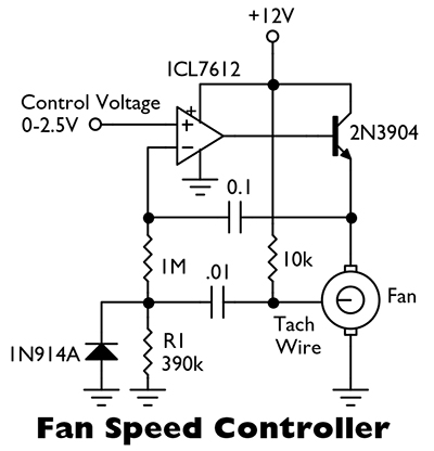
The feedback loop contains both differentiation and integration — the time constants of which have to be found empirically for a given make and model of fan (once found, they can be fixed for the same model). The values shown work for the majority of fans of this genre; resistor R1 determines the range of the control voltage: 390k = 0 - 2.5V, 180k = 0 - 1.25V.
Comments