With TJ Byers
Mirrors Yes, Smoke No
Question:
I’m looking for an advanced explanation — perhaps including some experiment suggestions — of the so-called diode-connected BJT and the current mirror. I’ve looked through all of my old college texts, the local community college library, and my county public library, with no success. I don’t expect you to devote a full column, but any pointers that you may be able to supply would be greatly appreciated.
Joseph F. Richmond
Answer:
For all intents and purposes, the diode-connected BJT (bipolar junction transistor) and current mirror are considered one and the same. While this circuit arrangement is often glossed over in college courses, without it the op-amp would never have come to see the light of day. In fact, the LM741 is riddled with them. Like you say, I don’t have the ink to go into depth on the subject, but an overview I can do.
This design starts with a transistor whose collector is wired to its base — essentially a diode junction. The cool thing about a diode is that it maintains a fairly stable voltage across the junction even as the current through it varies. In effect, Rbias establishes a constant current (Iref) through the collector of Q1. Now if you couple the base of the first transistor to the base of a second transistor, you create a current mirror.
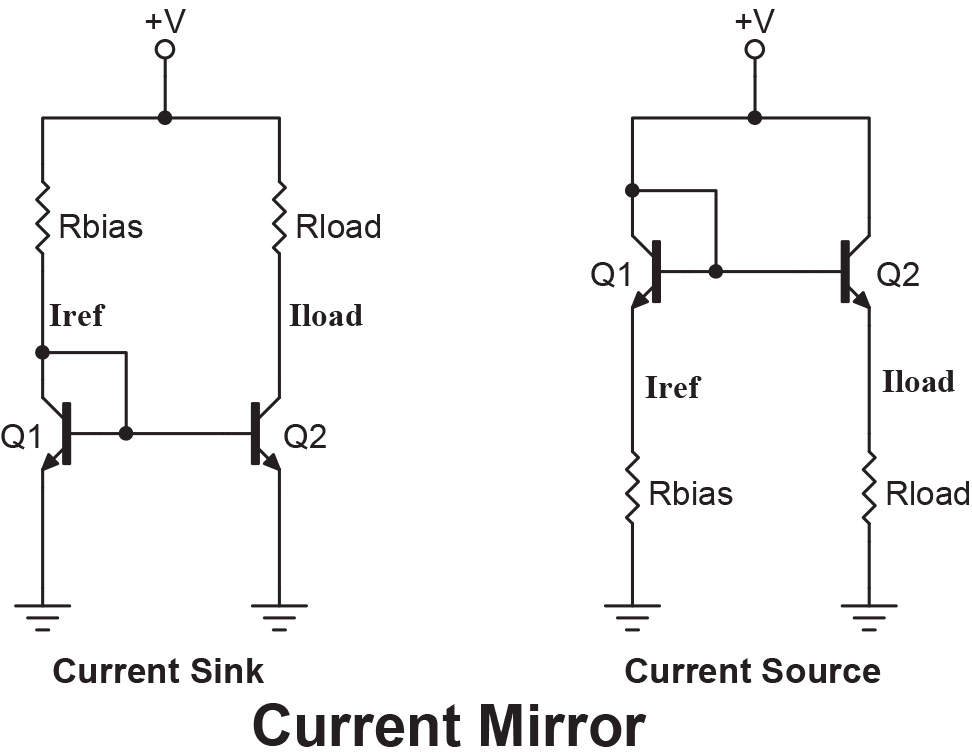
Whatever current flows through the base of Q1 also flows through the base of Q2, which, in turn, controls the current flowing through the collector of Q2. Here’s where it gets interesting, because the current through Q2 (Iload) is equal to Iref. What’s more, Iload is independent of the value of Rload!
Whether Rload is 1 ohm or 1,000 ohms, the current through it will always be equal to Iref. What we have here is a way to control the current through Q2 via Rbias. The circuit can also be rearranged for current sourcing — shown on the right — with no change in performance.
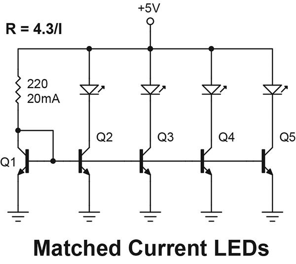
But the story gets even better. Theoretically, you can parallel as many Q2 transistors as you want — and they will all have the same collector current as Q1. Let’s say you have a bunch of LEDs you want to light, and you want them all to be the same brightness. This is a challenge for most applications because the brightness of an LED is directly proportional to its current flow.
Sure, you could string them in series, but that increases the voltage by the forward drop of the LED multiplied by the number of LEDs. That is, four red LEDs in series need at least six volts; four blue LEDs ups the ante to almost 20 volts. When you only have five volts to work with, a current mirror (below) is simpler than a boost switching regulator. Moreover, you can mix and match the LED colors and not have to worry about their forward voltage drop.
Of course, nothing’s perfect. In reality, the current flowing through Q1 is equal to the collector current plus the extra base current needed to drive Q2. This is why it’s important that the gain of the transistors be as high as possible, typically 300 or more, to minimize the error.
Other configurations have been devised — using additional transistors — to take the load off Q1’s collector. Heat, too, plays a role because the forward voltage drop of the base-emitter diode is temperature-dependent, and unless the two transistors are at exactly the same temperature, you’ll get an error. For further reading, go to the following websites.
www.4qdtec.com/csm.html
www.allaboutcircuits.com/vol_3/chpt_4/12.html
www.ece.cmu.edu/~ee321/spring99/LECT/lect17mar12.pdf
www.kettering.edu/~bguru/Pamp/PA-04.pdf
Comments