With TJ Byers
Op Amps And Filters Go Together
Question:
I have an electronic light organ board that I bought from Fry's Electronics. The color organ works fine, but at low volumes there isn't enough power to activate the triacs on the board, so the lights flicker. I need a stereo amplifier that will take in about half a watt and amplify it to about two or three watts. Instead of taking the easy way out and buying a kit, I want to make it myself. Can you provide me with a schematic of this amplifier? I have one more question about the color organ. While there are three channels on the board for bass, mid, and treble, the capacitors provided do not work very well — in fact, they don't work at all in filtering the sound. Can I make a simple filter with capacitors and resistors that will enhance the frequency-separation effect?
Edvis Shahbazian
via Internet
Answer:
The problem isn't lack of power, but not enough voltage. Power is the produce of voltage and current (P = EI), so as you reduce the volume you are also reducing the output voltage. You don't need a power amplifier, just a voltage amplifier — like an inexpensive op amp.
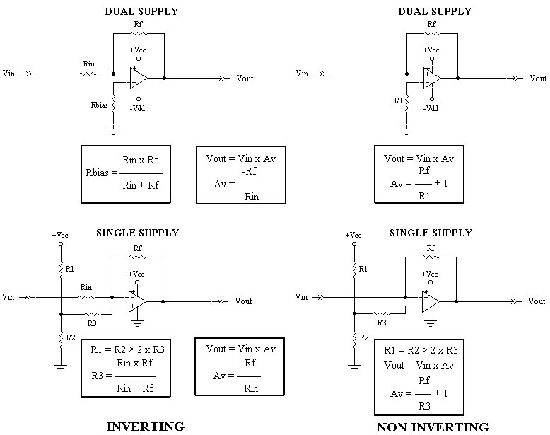
There are two common configurations for an op amp, inverting and non-inverting, as shown above. Simply put, the inverting configuration outputs a signal that is 180 degrees out of phase with the input, while a non-inverting amplifier keeps the two in phase with each other. Which to use depends on what you plan on doing with the amplified output. For most audio applications, the non-inverting configuration is used. Instrumentation and servo circuits often use the inverting configuration, which provides unity gain and negative amplification (attenuation). It's simple enough to calculate the gain (Av) needed for your application by measuring the output voltage of your audio source using a DMM in the AC mode. First measure it when the lamps are pleasing, and at the point where they start to flicker. Divide the higher voltage by the lower, and there's your amplification factor. Now choose a value for resistor Rf and run it through the equations.
As for creating a better filter using capacitors and resistors, it can be done using the same op amp. Basically, what you do is replace the Rf feedback resistor with an RC network, as shown.
The filters are basically pi-type networks that either enhance or cancel out the bass and treble frequencies. I've included a potentiometer so that you can balance out the channels to your liking. Each channel needs a separate op amp and filter, the output of which is plugged into the input of your present capacitor/resistor filters on the color organ board. The mid-range can go through unfiltered, if you wish.
Comments