With TJ Byers
Trapezoidal Light Fader
Question:
I am looking for a ramp generator, sort of. The ideal circuit would have a button which, when pushed would ramp up the output voltage, then the circuit would sit at a high output level until a second button was pushed which would ramp down the output voltage and then the circuit would sit at a low level until the first button was pressed again. I would really love it if the time of the ramp was variable between 0.5 and 15 seconds. And, finally, the output voltage should be 0 volts at low level and 10 volts at high level. The output current would not have to be very much, 100 mA max. The circuit would be used with an old analog theater dimmer pack. To make it even more versatile, if the output voltage high and low points could be programmed to 0-12V or 0-5V, then the circuit could be used in a variety of audio circuits, as well.
— Tyler Patrick
Answer:
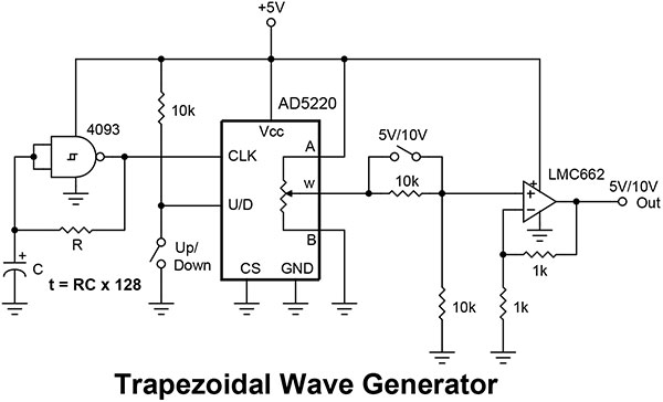
What you want is a trapezoidal waveform generator. This can be done using a digital pot (Figure 1). The first gate — a 4093 astable oscillator — clocks pulses into a 128-step digital potentiometer. Two SPST (single-pole, single-throw) switches determine the direction of counting, up or down, and the output voltage, +5 volts or +10 volts. Since you have three unused 4093 gates, they can be used to drive LEDs to indicate the direction of the waveform, output voltage range, and other functions. The power supply is regulated to five volts, giving the output a range of zero to five volts; the ramp-up and ramp-down time is determined by the equation t = RC x 128. The op-amp increases the five-volt wiper voltage to 10 volts at about 25 mA, which should be enough for most applications.
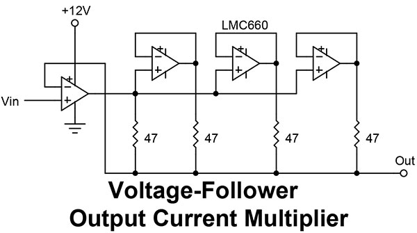
But you said you need 100 mA of drive. This is easily done by paralleling two or more op-amps to increase the output current. When paralleling op-amps, though, you have to be careful that they don’t feed back on each other and create unstability or overheating. The standard solution is to use small isolation resistors feeding a common line, as shown in Figure 2. There is no limit to the number of op-amps you can add to the right. However, it is better if they are all the same number — or at least the same type. Mixing parallel op-amp types is just asking for problems.
Comments