With TJ Byers
Wide-Range Current Regulator
Question:
I’m refurbishing a pair of old Hebern cryptographic machines and I think I need something rather peculiar in the way of a power supply.
The machine (from an electrical point of view) looks like a voltage source that is connected to the “left stator.” Then there is an alternating sequence of rotor-stator-rotor-stator-rotor-stator-rotor-stator-rotor, ending with the “right stator.” There are 26 possible paths through each rotor and each stator. The left rotor is connected to a keyboard; depressing a key “wets” one of the 26 contacts on the left rotor. The power is then transmitted through the rotors and stators to the right rotor, which illuminates one of 26 light bulbs to indicate the enciphered letter. The orientation of the rotors to the stators changes on a letter-by-letter basis.
I have rewired the rotors so that the resistance through each of the 26 possible paths in each rotor is less than 1Ω. That was, comparatively, easy. The problem is that the intermediate stators are built out of contacts and springs (98 parts per stator!) and the resistance through each of the 26 paths in the stators is not uniform — varying from about 1Ω to about 4Ω, depending on the particular stator and path.
Can you show me how to build a power supply that has the following characteristics?
- If it sees an open circuit (say, more than 100 W), it doesn’t panic and produces no output.
- If it sees a resistance of 10 W, it cranks out 3 volts at about 0.3 amps.
- If it sees a resistance between 10 and 100 W, it puts out whatever voltage is required to develop 0.3 amps.
Peter Ingerman
via Internet
Answer:
What you need is a constant current power supply of 0.3 amps or 300 mA. This is easily accomplished using an LM317 adjustable voltage regulator.
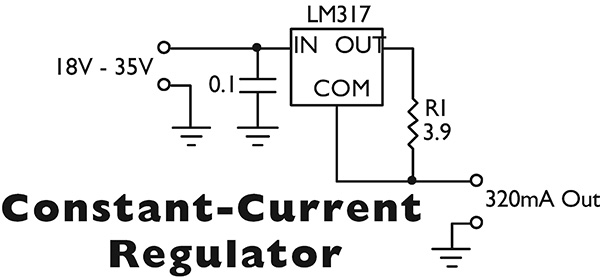
Resistor R1 determines the output current of the LM317 by setting the current of the internal reference voltage, which is 1.25 volts. If R1 is 1.25Ω, then the output current will be 1 amp; a 3.9Ω, 1/2 watt resistor limits the current to 320 mA.
Now, let’s determine how much voltage is needed to push 320 mA through a 100 Ω load. Using Ohm’s Law, E = IR = 0.32 x 100 = 32 volts. Because the LM317 needs at least 3 volts to operate, the minimum input voltage is 35 volts DC. If you can live with an upper limit of 50Ω, the minimum input voltage is 18 volts, which is easily obtained from a cheap wall-wart. Be sure to heatsink the IC because it can run hot — up to 10 watts with a shorted output.
Comments