My Internet router is located near our entertainment center in the family room. There are only four Ethernet ports on the router and I have five pieces of equipment that need to plug in. I also run a cable from the router to my home office (in the back of the house) that connects to an Ethernet switch that provides Internet to multiple computers, VOIP phones, as well as network connections for various printers.
At the router, I have to plug and unplug whatever equipment I want to use, since I don’t have enough ports to keep it all plugged in. Some devices can use the Wi-Fi, but performance is better and more reliable on the wired connections.
Questions:
- Can I add another switch at the router to expand the number of ports?
- What are the limitations/drawbacks on adding more switches to the network? (I currently have two in the office.)
- Is there a better way to do this?
#03193
Byron Rochefort
Fort Wayne, IN
Please log in to post an answer.
Answers
The easiest way to get more ports is to just buy a new router or switch with more ports than the one you currently have! It sounds like you have a 5-port router driving your Entertainment Center, so I suggest replacing the 5-port router with an 8-port Router (i.e., https://www.amazon.com/D-Link-Gigabit-Dynamic-Filtering-DSR-250/dp/B008021NSI/ref=sr_1_5?keywords=8+port+internet+router&qid=1566511970&s=gateway&sr=8-5). Because routers intelligently manage the output ports to ensure that each port will have maximum bandwidth and manage Network addressing (via DHCP, etc.), they’re always more expensive than unmanaged switches.
Unmanaged Switches, OTOH, simply connect to a source port (i.e., one network address) and simply devide the incoming bandwidth to each active device on the other ports, depending on how many connected devices are active, relying on the source port (usually a modem) to do all the port management (DHCP routing). In other words, if you have a 1000 megabit source (i.e., cable modem feed) connected to one port of a 5-port switch and 4 output (i.e., smart TV, game console) devices connected to the other 4 ports, each output port will only see a maximum of 250 megabits of bandwidth (1000 megabits/4 active outputs) IF all 4 output devices are simultaneously active. As the number of active devices decreases, the per-port bandwidth naturally increases. Only ONE active output device will receive full bandwidth from the input source. This is why unmanaged switches are much cheaper than routers, because they use something else to take care of address, etc. management.
Therefore, these are your choices:
- If you want maximum throughput to all your internet devices, invest in a router that has lots of output ports. This is the mo$t expen$ive option as more ports = more $$$. However each active output port will see a pretty high bandwidth due to the router’s intelligence.
- If per-device throughput isn’t an issue, invest in HIgh-Bandwidth (Gigabit) unmanaged switches that have more than five ports each (i.e., 8-port, 16-port, 24-port). While the more ports = more $$$ formula still applies, their cost is still proportionately lower than routers with similar port configurations.
When dealing with Area Networks (home or business), It’s always wise to have more available ports (router and/or switch) at all stations (Home Office, Entertainment Center, etc.) than there are active network devices so you have expansion capability if you desire (i.e., extra printer, extra computer, etc.).
Ken Simmons
Auburn, WA
Adding a switch to a router port is OK. The router will only send the packets that are addressed to the devices on the switch. The negative is that the devices on the switch have to share the bandwith of that one port. Put devices that have low usage or not used at the same time on the switch. The alternative (better way) is buy an eight port router. The switches also come in larger number of ports.
Steve Benson
New Castle, IN
Let's take you questions one at a time.
- Can I add another switch at the router to expand the number of ports? — Yes, up to the theoretical maximum of 254 ports.
- What are the limitations/drawbacks on adding more switches to the network? — I've experienced no problems. I have about 45 Ethernet devices and 22 WiFi devices in my home. I have both 8 port and 24 port gigabit switches plugged into the router plus two 8 port switches plugged into the 24 port one. Additionally, I have 5 port and 8 port switches located in several rooms that go back to the 24 port one as well. With 9 HD IP cameras and streaming services running I found that using gigabit switches (10/100/1000) eliminated any issues.
- Is there a better way to do this? — With gigabit switches costing as little as $10 you'd be hard pressed to find an easier or more economical solution. With a total of seven switches in service I have a highly reliable network.
Bruce Robin
Naples, FL
The main limit with today's switches, even the cheapest, will be the total number of IPs used on your local network. This sets a practical limit to about 240 ports less the number of WiFi connected devices. I would consider an inexpensive Dlink / Netgear / TPLink / TrendNet "Green" 8 port gigabit switch at the router; this will give you five empty ports when finished. I'd also move all the connections off the router for the inside (the four you've got plugged in now) and run this switch off one of the router ports, and the two remote switches off of two of the other ports, leaving the non-switch items on the new switch.
Ralph Phillips
Bossier City, LA
1. Yes. I have the exact same problem, so I plugged a small 8-port Cisco switch (SG110D-08) into one of the ports on my router, and it works great.
2. There may be a practical limit to how many switches you can cascade, but I have another switch plugged into the first one to service some equipment in another location, and it works just fine. Ideally, to avoid any latency when going through multiple switches, you may want to plug all switches directly into the router if it has enough ports, but it will work fine if the switches are cascaded.
3. Replacing your router with one that has more ports would probably be the ideal solution, but the above is cheaper and works well.
Gary Rathbun
Placerville,CA
Yes, just add another ethernet switch with a short cat5/6 jumper to the switch on the back of the router to which you wish to expand the ports. The ports on the back of a router are really "switch" input/outputs.
William B Runyon Sr
Chesapeake, VA
I need to put the speaker-level output from a PA system on a POTS telephone line. I don’t need dialing capability, as I can connect a POTS phone to make the call, but once the call is established, I need a circuit that will:
- Hold the phone line open, as I’ll hang up the phone I used to make the call.
- Put the PA output onto the phone line, preferably with adjustable volume. I can attenuate the speaker-level PA output to line level if necessary.
If a reasonably-priced product with good sound quality (i.e., no hum, etc) is already available to do this, suggestions are welcome. I’ve found many products for recording phone conversations or putting them into a PA, but only quite expensive ones with way more features than I need that will do the simple job I want.
Thanks for any help/suggestions.
#04191
Gary Rathbun
Placerville, CA
Please log in to post an answer.
Answers
All you really need is a “wet” 600 to 600 ohm transformer. The “wet” designation is for a transformer that will work properly at audio frequencies with up to about 100 mA of DC flowing through the POTS side winding.
Connect it directly across the telephone line through a switch. Then apply the audio attenuated down to a low level to the other side of the transformer. Make sure that you don’t apply very much audio, as there are FCC regulations regarding the maximum audio levels. See FCC part 68 for the particulars.
Richard Cox
Thousand Oaks, CA
You can find music on hold adapters that will do exactly what you want, like the On-Hold MOH 150 for about $15 on ebay. You can plug the PA line into the device and it will play on the phone by putting it on hold from the device.
Bruce Robin
Naples, FL
I’m building a rear facing camera system for my car that displays the image on a 7” screen mounted on the dash. However, the image appears reversed horizontally. Is there a circuit to flip the image left to right so it would be correct from the perspective of the driver? Any ideas are appreciated.
#03192
Krystian Czarnecki
Lombard, IL
Please log in to post an answer.
Answers
Your best bet is to buy a backup camera that reverses the image for you. Many models let you select which way you want the image displayed. Depending on the resolution and night vision features you want, the backup camera can be purchased for under $20 online.
Bruce
You don't need any electronics. Instead of having the camera face backwards out your rear mirror, place it so it "looks" left or right. Then use a mirror at 45 degrees to the camera's optical axis (top view) and you'll get a left-to-right reversal of what your display shows. You could mount the camera and mirror on a plastic or plywood base and support the mirror with a small angle bracket that lets you adjust the angle so it suits your purpose. And you can move the base as necessary.
Jon Titus
Herriman, UT
I’m looking for some pointers on winding coils. On a second layer of winding, should the direction reverse when reaching the end of the core, or return to the starting side and wind in the same direction? It seems like winding in the reverse direction would cancel out the field. Does it matter which direction?
#1194
Jordan Bracegirdle
Toronto, CN
Please log in to post an answer.
Answers
Assuming that the coil is being wound on a bobbin or other form, the coil is wound beginning at one end, laying down the wire turn by turn until the opposite end of the bobbin is reached. At this point, winding continues in the same direction, but proceeding turn by turn back to the point of beginning, and so on. For an inductor, it doesn't matter which way you wind the turns so long as you're consistent throughout.
Others have raised this question; see, for example, https://electronics.stackexchange.com/questions/369884/how-to-wind-an-inductor.
A good document on building inductors was found on the ARRL site:
http://www.arrl.org/files/file/Technology/tis/info/pdf/9708033.pdf.
Good luck.
Peter A. Goodwin
Rockport, MA
It's the direction the current flow rotates around the former that matters. This does not change when your winding goes back along the core.
Kit Wareham-Norfolk
Exmouth, Western Australia
It is OK to wind a bobin from one side to the other and back. That is the way it is normally done. If you were to go back to the same side every time, you would end up with a nasty bump in the coil layers where the wire returns. And no, that does not cancel the flux field. Looking from the end of the coil, the windings are still in the same direction, either clockwise, or counter clockwise. If you were to change direction, say part of the coil is clockwise, and you now reverse that direction to counter clockwise on the next part, than those windings would cancel out the same number of earlier windings (in an idealized scenario). Those windings would become a simple resistor from an electrical perspective.
Bill van Dijk
Carp, CANADA
I’m looking for a circuit using a piezo buzzer, that I can hear from the room above the cellar. It will be connected to a Taco Heating Zone Valve on the boiler in the cellar for troubleshooting the thermostat when it goes on and off.
#3194
G Forcino
via email
Please log in to post an answer.
Answers
I’m looking for a circuit using a piezo buzzer, that I can hear from the room above the cellar. It will be connected to a Taco Heating Zone Valve on the boiler in the cellar for troubleshooting the thermostat when it goes on and off.
Get a DC-DC converter like this one:
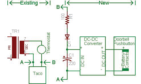
DC-DC Buck Step-down Regulator Converter 4.5~65v to 3V 6V 9V 12V 24V 48V Module
Get a diode, resistor and capacitor per the schematic and build the new circuit. Note the capacitor must be rated at least 35 volts. Connect the new circuit to the existing circuit, A to A and B to B.
The diagram shows a doorbell push button - more on that later. In place of the doorbell push button you can connect whatever piezo you want that is within the capability of the DC-DC converter you get. The problem with piezo buzzers is that it is impossible to predict whether you will hear them from the room above. A cheap (<$10.00) solution is to use a wireless doorbell. For that, read on.
Get a wireless doorbell from eBay like this one: https://www.ebay.com/itm/400ft-Wireless-Doorbell-Twin-Wall-Plug-in-Waterproof-Cordless-Door-Chime-Kit/152986512099?hash=item239eb4eae3%3Am%3Amxl6HSV0iPKKQ83VnZkaAfw&LH_BIN=1
Set the output voltage of the DC-DC converter to match the battery voltage of doorbell push button circuit. The battery will not be used. Short the switch contacts inside the doorbell push button.
When the thermostat sends 24 VAC to the Taco, the DC-DC converter will output whatever voltage it is set to to make the wireless doorbell chime or the piezo buzz. When the thermostat is open, there will be no voltage out of the converter.
Ed
via email
I have a bunch of old optical disks that have data archived from about 20 years ago that I would like to access. I found the stand-alone drive in a box of old computer junk, complete with the big SCSI cable. Problem is that I don’t have the computer anymore that has the SCSI card to plug it into, and don’t even know where to begin to look for one.
Is there something comparable that will work with a modern computer? An SCSI to USB adapter maybe? What about drivers? The old machine was probably Windows 98.
#1192
Mark Cisneros
Columbia, TN
Please log in to post an answer.
Answers
I have a Win98 computer set up to read SCSI disc drives. It was a bear to create and find drivers for. I’m in Phoenix Arizona.
My next question is what software would be needed to read the data, is it just text? My setup was crated to be able to read and copy SCSI to sim cards, because of the lack of production of SCSI drives. I can currently copy from SCSI to sim cards if that would help. SCSI is old technology that is not really supported. If the data is important, I could probably read your drives and forward the data back in a usable format.
Let me know.
Antoinette Sides
via email
Adaptec made a USB 1.1 and a USB 2.0 SCSI to USB adapters; USB 1.1 M/N FX0C21902KL P/N 1861400; USB 2.0 M/N FX0A229005U P/N 1989100. I have one of each and they worked on every device I tried them on. Obviously the USB 2.0 is faster. I think the main drivers were Windows 98, but I can't recall for sure. I think I used them last under Windows XP.
Alexander Fisher
Galloway, OH
There are still PCI cards available for your SCSI drive, although they go by either GPIB or IEEE488 interface. National Instrument has both the cards and drivers (http://www.ni.com/en-us/shop/select/gpib-instrument-control-device). It would be difficult to connect the SCSI drive to the computer with a USB connection since the drive requires several control lines for proper access.
Lance Corey
Santa Ana, CA
I find some SCSI/USB adapters on eBay for around $170 to $300 each. I also find brand new SCSI/PCIe host adapters on Amazon for under $100. Either way, unless your cable is a Macintosh style cable (DB/25 to AMP50), you’ll also need a new cable. (For most of the PCIe host adapters, you’ll still need a new cable). What make and model are the optical disks? You may be better suited to pick up a used MO drive that’s SATA and use it on your current PC. Or with a SATA/USB adapter externally.
Ralph Phillips
Bossier City, LA
Is it possible to replicate tubular bell tones with a microcontroller? I’m needing realistic, deep, resonating tones. If so, are there any micro requirements that would make one device more suited over others and how do I create the tones? I want to program short 10-15 sec jingles of my own composition.
#1193
Sara Hanchett
Forest Grove, OR
Please log in to post an answer.
Answers
For the best result I would look at a MIDI solution with a sampled sound file.
Bill van Dijk
Carp, CANADA
There are a number of articles in the past issues of Nuts & Volts for a variety of ways to control devices in a home using a variety of control devices and schemes. However, none seem to have the combination of characteristics that I want. I would like to control a pair of simple low current AC sockets (ON/OFF) from my cell phone. I would like to use a combination of an existing app, a PIC style device (Ardunio or whatever), and a Wi-Fi module to connect it to my existing Wi-Fi. I do not see why a $100 hub should be needed. My present cell phone uses the Windows operating system, but I know that apps for it are scarce and I am willing to get an Android device. I’m stuck on finding the cell phone app and the Wi-Fi module. I would assume that I would have to write the appropriate code for the PIC device. I can interface the PIC with a relay, probably a solid state one. Any suggestions?
#3193
Edward Alciatore
Beaumont
Please log in to post an answer.
Answers
If all you want to do is to be able to remotely control an AC outlet via a mobile device from anywhere, then simply buy a WEMO Mini Smart Plug. These are sold in Home Depot for about $25. They connect to your home WIFI, are very easy to install and have APP’s for both Android and Apple IOS devices.
These Smart Plugs have a switched AC outlet capable of carrying up to a 15A load. No code to write, nothing to build, just download the APP, plug the WEMO Smart plug into any AC outlet, follow the APP instructions and you’re up and running in five minutes. Install as many devices as you need remotely switched outlets.
Roger Baker
Redmond, WA
The easiest way to do this would be to buy some TP-Link KASA modules. No hub required — just plug them in, load the app and in a couple of minutes you’re done. AND, they work with Alexa/Google Home.
Bruce Robin
Naples, FL
Sonoff makes a bunch of home automation wifi devices. I have several of their products which I got off Ebay and AliExpress. Just type “Sonoff” on the search line. They do a lot more than just switch devices on or off. I paid about $6 for a single channel and about $15 for a 4 channel. Rated 10A @120VAC.
Simple to setup, the device just needs to be within range of your router. The free app is only available for Andriod/Apple phone, although they say you can use a PC if you run it thru an “Android Emulator” program. Never tried this though.
Harold
Rochester, NY
DC To AC
Answered
2019 Issue-1
I have a 100 amp 110 volt DC generator. I want to convert the output to 60-cycle AC. Does anyone have a schematic or info to build a converter? How much power loss can I expect in the final converted output? Thanks for any info.
#1191
Lucio Saunders
Indianapolis, IN
Please log in to post an answer.
Answers
You don’t need a converter. You need an inverter. A converter is used to change AC into DC or DC of another voltage, while an inverter changes DC to AC. That being said, there are many ways to skin this cat, depending on how much you want to spend and what you want to use the AC output for. Before we go there though, we have to start with basics: the generator.
In your question, you did not specify the type of DC generator that you have or how you are driving it. There are three types: the shunt; the series; and the compound. Each has its own set of operating characteristics. I assumed that yours is of the shunt type, the most common. The Rheostat (R) is used to adjust the output. The voltage (E) and current (I) are monitored and the output is supplied through a 125 amp fuse.
Your generator is rated for 100 amps at 110 volts which is 11,000 watts (11,000/750 = 14.67 horsepower). Add 20% because no generator is 100% efficient, so about 18 horsepower is required to drive it at its rated speed. This is important because the output of a DC generator is related to both its field strength and operating speed.
There are three ways to do what you want to do.
The first option is the simplest — just use a 110 volt DC to AC inverter. These are around because they were once used on small hydro electric systems. You may be able to find one on the Internet, but I don’t recall any being large enough to handle 11,000 watts.
The second option is a bit more radical, but much more feasible as the inverters are widely available for usage in the alternative energy field. A pair of 48 volt magnum energy MS4448PAE inverters are connected in series and these are in parallel with a pair of series connected high-value capacitors. An equalizer line runs from the junction of the capacitors to the junction of the inverters. This works because these inverters like to operate around 55 volts and because their outputs are in parallel, they share the load evenly. The equalizer line is a safety to handle any imbalance.
As for output, these inverters are rated for 4,400 watts continuously, 4,800 watts for 30 minutes, and 6,000 watts for 30 seconds. The first two specifications are all that matter in your application. Assuming 90% inverter efficiency, the generator will supply 9,680 watts (88 amps) to produce 8,800 watts of AC. The generator will supply 10,560 watts (96 amps) to produce 9,600 watts of AC for 30 minutes at a time.
The third option is the most radical, but it allows two things the other options do not: redundancy and the ability to supply AC to the utility grid. This option utilizes microcontrollers commonly used on photovoltaic modules to convert low voltage DC into 60 Hz and then to synchronize this to the utility grid. I have chosen the Enphase Energy 250 watt unit. You will need 36 of them and they are used in groups of three to allow an input of 48 to 144 volts. This is well within the range of your generator.
The outputs of all the units can be connected together to produce about 9,000 watts of AC power at 120/240 volts or they may be connected for three-phase output at 208/120 volts. They must be connected to the AC grid to operate though. By having 36 units in 12 series strings, the failure of a single unit will only reduce the output by a little more than 8%. It was nice talking about the good ole days of DC. If you have any other questions, you can contact me directly at PO Box 9106, Concord, MA 01741.
Craig Shippee
Concord, MA
My brother has an old MG that he likes tinkering with. He wants to use the side lights to indicate when the turn signal is on for drivers that are on either side of him. Normally, the side lights turn on and off with the headlights.
In his case — and to reduce peak power consumption to the blinker circuit — he would like the side lights to turn on when the signals are off, and vice versa (when the turn signal switch is turned on). Additionally, if the lights are on, the side lights should give priority to the turn signal, turning on and off, opposite to the signals in the front and rear, and returning to full on when the turn signal is not engaged.
I think the simplest way to do this would be with solid-state relays and the use of some logic gates (for each side). I have built hundreds of logic circuits, but have not really dabbled much in automotive applications. I know the electronics have their own temperature and performance specs and are noisy environments, not to mention the notoriously bad reputation that English cars have for electrics. Can you recommend a circuit for this application? (This car is a NEGATIVE chassis).
#3192
Patrick Gilmore
Amherst
Please log in to post an answer.
Answers
This is what we do in the DeLorean community for a similar effect. We also have a negative chassis but our side markers are not grounded to the chassis, but rather through their own separate wire. I am not sure how an MG does this. If the MG side markers are grounded through the chassis, perhaps you could find a suitable socket with two separate wires. Maybe also switching to an LED if wanted/needed.
Simply disconnect the ground wire of the side marker light and connect it to the positive side of the parking lights.
When the parking lights are off, the side marker will flash in sync with the turn signal lights, using the parking light bulb as a ground path.
When the parking lights are on the side marker will light up, using the turn signal bulb as a ground path and blink off, ie. out of sync, with the turn signal.
Dave Delman
Jericho, NY
Solid state relays are not ideal for this application. Automotive relays are cheaper, handle more current and are designed for the environment.
A 4 pack of automotive relays including the wiring harness from Amazon (for $9.97) will do what you want: https://www.amazon.com/Pack-EPAuto-Relay-Harness-Bosch/dp/B072QXDZRD
The diagram shows the wiring for the left side only. You need to duplicate it for the right side. RY1, when energized by the turn switch, gives priority to the turn signal. RY2 allows the side lights to light when the turn switch is on and the turn bulb is off. When the blinker turns the turn bulb on, the side light turns off, and vice-versa.
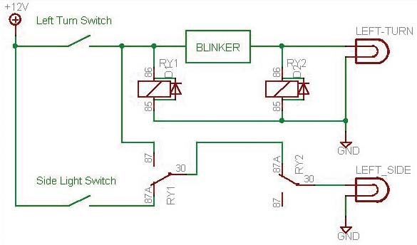
Add a 1N400x diode across each relay coil as shown in the diagram.
Ed
via email
I have wired many cars this way as car makers also do this on some models.
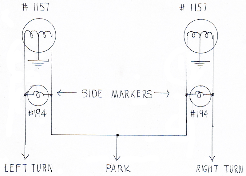
The side light can not be grounded. I have replaced the sockets in the side makers to a 194 bulb socket available at all auto parts stores.
In the day time, the side lights alternate blinking with the turn signals and ground through the filament of the park bulb.
At night, the side lights come on with the running light, flash opposite the turn lights, and ground through the turn light filament. (when park and turn are both on you power on both sides of the side light).
You can see this on many cars and trucks at night when turning, if you are observing things at night. I have also done this at rear of car when possible.
Only a special part may be a side light socket. If it’s a bayonet type socket, it has to change to a 194 insulated socket that is readily available.
John Obenchain
via email
My 1988 Dakota has side lights like that. They’re just 194 type bulbs (you could use something like a 721 if you wanted really bright), connected across the turn signal hot and the parking light hot.
When the parking lights are off, you turn the turn signal on, the current flows through this bulb, then through the parking light filament, and it lights up. When the parking lights are on, and the turn signal is off, current flows from the parking light lead through the turn signal filament and the bulb lights up. When the parking lights are on, AND you have the turn signal on, both leads are at the same potential, and the light turns off. This will be complicated by LEDs, but for incandescents, it’s bog cheap, bog simple, and does what you’re asking for.
Ralph Phillips
Bossier City, LA