About Resistors
Answered
November/December 2018
Could someone explain what pull-up and pull-down resistors are, when and how they’re used, and how to calculate their values?
#11187
Andy Dietrich
Dallas, TX
Please log in to post an answer.
Answers
Resistors are used in a number of roles in circuits. The terms “pull up” and “pull down” are used to describe two of those roles. A somewhat precise statement of the definition of a pull up resistor would be that it is a resistor where one side/lead is connected to a circuit device, often a transistor or FET or other active device, and the other side/lead is connected to the positive power supply voltage used for that circuit. Thus, it is trying to “pull” the terminal of that device “up” to the level of that power voltage. A “pull down” resistor would be the same idea but with the negative power supply voltage or ground in place of the positive one.
Active devices, like transistors, can be modeled as a variable resistance that is controlled by the base current: the greater the base current, the lower is that effective resistance (emitter to collector). So more base current equals more current in the emitter-collector circuit. But that, by itself, is not very useful in most circuits where an amplification of the voltage is what is needed. By adding a “pull up” or “pull down” resistor, depending on the polarity of the transistor and the arrangement of the circuit, a voltage divider is created. That voltage divider consists of the fixed resistance of the “pull up” or “pull down” resistor in series with the variable resistance of the emitter-collector path through the transistor. The output voltage is taken at the junction of the resistor and the transistor. That is where the variable current is converted to an amplified voltage.
The idea is pretty much the same with FETs and other active devices. “Pull up” and “pull down” resistors are also used with switches. The resistance of the switch is also variable: either zero or infinite. In that case the resistor will pull the output of the switch all the way to either the positive supply voltage or to ground.
The values of the “pull up” and “pull down” resistors are usually calculated with Ohms Law. The circuit designer must have a value for the current that will flow in the resistor/transistor circuit. There will be several concerns for that value including the load impedance, the current rating of the transistor, the desired point of operation on the characteristic curves of the transistor, the amount of quescient current that is allowable/desirable, and others. Once that current value is determined, it is combined with the supply voltage in Ohms Law to find the value of the “pull up” or “pull down” resistor. R = E/I
If the current is significant a calculation of the power dissipation in the resistor should also be made: P = VI where V is the supply Voltage and I is the maximum current that can flow in the resistor. A general rule is to use a resistor that is rated at two times the power level that this calculation produces as a safety margin. Often (usually) the resistance value of the “pull up” or “pull down” resistor is made as high as possible in order to avoid the use of high power resistors.
Edward Alciatore
Beaumont, TX
Pull-up or down resistors does not refer to a type of resistor, but its function. Usually their purpose is to give a high impedance wire a known state. For instance, an output pin on a MPU may be an open collector output, capable of sinking a few mA. When it is activated, its state is grounded. When released, it floats, and has no definable state. In this case a pull-up resistor connected to the supply line would give it now a high level.
Pull-ups and pull-down resistors can be used in many locations, another example would be in an I2C buss. Read up on that, most descriptions will do a good job of explaining how it works.
Bill van Dijk
Carp, CANADA
The basic idea of a pull up or pull down resistor came from some logic families which had output pins connected to the collector of the output transistor stage. There was no internal connection to a power supply, so the output did not respond to logic states if no other connection was made. A suitable resistor was tied to the plus supply, so when the base of the transistor was held low the output went to the supply voltage (pulled up to the supply), and when the base of the transistor went high it would pull down the output to ground. The open collector allowed outputs to be wire ORed together saving parts. By connect several outputs to the same resistor, if any of them them went low it would pull the resistor down (an OR situation).
Values for these are usually suggested in the data sheets for the parts. To calculate a value get the max output current from the data sheet and use your supply voltage and ohms law to compute the smallest allowed resistor.
The idea has been extended to resistor networks which aid in driving high speed signals through long lines. A google on impedance matching and line driving will get you started on this variant.
Warren O Wilderson
Eagle Point
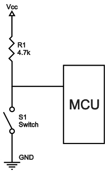
Pull-up and pull-down resistors once baffled me, too. Very often a device, say a 555 timer, will require a ground pulse to start a timing cycle. This means that one might install a momentary switch to ground to activate the timer. Well, if that pin on the chip is not already in some known state, it can behave differently each time it’s powered up. It may work as designed, it may not. If the wind blows from another direction, it may behave differently because it is “floating.”
Now, you could just connect it to the voltage that’s supplying the chip, but if you then forced that to ground, you’d have a short circuit and something is going to burn. If you have something held to supply voltage, say 12 volts, by way of a 10k resistor, it will sit there seeing 12 volts. If you then press the momentary button, the subject pin will see it as a ground and the 12 volts will cause 1.2 mA to flow momentarily.
So, you don’t have a short, the activating pin sees a ground pulse and starts working, and you won’t damage your circuit. Leaving any pin, even ones that specify “NC” (no connection) floating, may yield unexpected behaviors and not always the same “unexpected behavior.” In this case, it’s good practice to ground pins labeled “NC” either directly or by way of a “pull-down” resistor. If you always use a resistor, you minimize the chance of a short circuit even if you made a mistake in grounding the wrong pin. Hope this helps!
Brendan Ames
Albuquerque, NM
A pullup/pulldown resistor resolves a voltage ambiguity that may exist on a circuit node. These resistors are commonly used with transistors in digital switching operations.
A pullup resistor connects a node to logic 1 voltage (eg 5V) and a pulldown connects to logic zero (ground). For example, a bipolar transitor used for digital switching has a pullup resistor connecting logic 1 voltage to the collector node, i.e. the transistor switch output. When the transistor is off, no current flows through it or the pullup resistor. Ohm’s Law shows there can be no voltage drop across the resistor, hence the voltage on the collector must be at logic 1. When the transitor is on, current flows through the collector and pullup resistor. A voltage drop now exists across the resistor causing the collector voltage to drop below the level of logic state 1. The more current that flows, the bigger the voltage drop.
When a component is specified as open collector, the designer must supply the pullup resistor. This is the case for the I2C communication interface. The designer may choose a large pullup resistor to limit current and extend battery life. But there is a trade-off due to unavoidable stray capacitance (C) at the output. A large resistor will increase the RC time constant and slow down the response.
Mike Hasselbeck
Albuquerque, NM
Pull-up and Pull-down resistors are used to force an input signal line to a default level when there’s no external input applied. Typical pull-up values for Digital lines are between 1Kohm and 10Kohm, connected between the V+ line (i.e., +5 VDC) and the signal line. Pull-down resistors do the same thing, except they’re connected between V- (or GND) and the signal line, and are usually no smaller than 4K ohms.
To calculate the resistor size, you need to know how much current is going to flow INTO the line (pull-up) or flow OUT OF the line (pull-down). You typically don’t want more than 20 milliamps of current flowing through a pull-up nor do you want more than a few milliamps flowing through a pull-down. For +5V logic, pull-ups from 1K to 4.7K are sufficient. You rarely see pull downs with +5V logic, but they are needed sometimes. The power rating of the resistor is calculated using the (I^2) x R, and rarely goes above ½ watt.
You can connect a pull-up and pull-down in series, with the resistor junction connected to the signal line to form what’s called a receiver. You’ll typically find these on serial communication lines where the SIGNAL LOW value is a negative voltage. The pull-down resistor will usually be sized with the pull-up to create a voltage divider. You can find dividers with CMOS and +3.3V logic where you don’t want the HI to go above a certain value nor the LOW to go below 0V (GND).
Here is a good reference: http://www.resistorguide.com/pull-up-resistor_pull-down-resistor/.
Ken Simmons
Auburn, WA
To begin with, positive voltages are considered ‘up’ and negative voltages are ‘down’. A resistor connected to a positive voltage on one end and to a circuit element on the other end will be pulling the circuit element up to the positive voltage, if there is no current. If you want current to flow, you must figure how much and compute the resistance from: R=V/I; where V is the voltage drop across the resistor. Pullup resistors are often used with an IC that has an open collector output.
Pulldown resistors are most often used on the emitter of an NPN transistor. If the base of the transistor has a positive voltage applied, the negative voltage could be zero (ground). In any case, you need to know something about the circuit to compute the resistor value.
Russell Kincaid
Milford, NH
My cable system needs frequent resets. That means turn the power off to the cable box (router) and to my own WiFi router, wait 30 seconds, and turn the power back on. This is really aggravating when I am in the bedroom or the garage shop trying to watch streaming video on my TVs there and the routers are at the other end of the house.
I want to build a WiFi based system so I can activate a control to cycle the AC or DC power from anywhere in the house either via one of my computers or my cell phone. Now, my phone is a smart phone, but not a name brand like Apple. It’s a Nokia and uses the Windows operating system, so the available apps are somewhat limited.
So, I’ll need an app that will work there and one that will work on my desktop computer running Windows 10. I would like some ideas on how to proceed. I would think that I could base this on an Ardunio or other single board computer which could easily handle a 30 second time-out.
I can figure out the interface to the power relay, some local PB controls, and a display. But how do I handle the controls through the WiFi? I need advise on a WiFi interface and the apps that are needed to activate it.
#03191
Edward Alciatore
Beaumont
Please log in to post an answer.
Answers
The problem with your premise is that if the router and cable modem are not working (hence no internet or WiFi) how will you use WiFi to trigger the reboot?
The first thing I’d do is get to the bottom of why you need to do such frequent reboots. Is it the cable modem or the router that’s causing the issue? Personally, I’ve found cable modems from the ISP to be problematic. You’re probably paying $10+ tax a month to rent it when you can buy your own for under $100 - that’s a 10 month or less payback!
How old is your router? Best to use a router with gigabit ports if your streaming HD videos. As we started doing more streaming I also found that using gigabit switches improved performance dramatically particularly with ten IP security cameras running. I do use my router’s auto reboot feature nightly as we travel a lot but, unless the cable company has had an outage, I never have to reboot the modem.
Bruce Robin
Naples, FL
This may not be what you're looking for, but I've installed a metric boatload of these units for remote control of WiFi systems at banks and hotels. https://www.amazon.com/POWER-SWITCH-WLCD-SCREEN-OUTLETS/dp/B00EZWD146?ref_=fsclp_pl_dp_2
What you can do to make it even easier is set it up downstream of the router and modem, and have it ping something like, say, Google's DNS servers every 30 seconds. If it doesn't get a response, wait for up to 5 failures, then power cycle both outlets. You can also web browse to the interface, and hand cycle both; this supposes that the WiFi isn't built into the router (which if your main access point IS built into the router, you won't be able to turn it back on via WiFi anyway!) This is not the only way to do it; but it's one that works and is solid and reliable.
Ralph Phillips
Bossier City, LA
Is there a way to vary the speed of a music CD player? I play my instruments along with the recordings and need to vary the pitch slightly to match the tuning of my instrument. We used to do this easily with vinyl by varying the speed of the turntable.
#11188
Klaus Herman
Raleigh, NC
Please log in to post an answer.
Answers
CD players for professional/DJ market have variable pitch built in.
Erik von Seggern
Escondido, CA
I would be surprised. CD players are designed to KEEP their speed. I would convert the song to one of the usual audio file formats (mp3, wav) and run it on a computer with the free audacity tool. That lets you change the speed and even allows you keep the pitch! (Effect -> Change Tempo; Effect -> Change Speed). I use audacity constantly.
Werner G
via email
Anybody doing SMT reflow soldering at home? Trying to make the switch from TH to SMT. I was wondering what homebrew oven setups people are using and any tips and advice for a newbie.
#11183
Joey Dampier
Reston, VA
Please log in to post an answer.
Answers
Yes, I do SMT soldering using an electric skillet. Search the web for "solder skillet," there is a good write-up from the folks at SparkFun. Five to six minutes at 400 degrees Farenheit works great. Parchment paper under the board provides a way to lift it in and out of the skillet. Also, reasonably-priced hot air rework stations are now available, check CircuitSpecialists.
When I first started SMT, solder stencils were very expensive so I used the individual component stencils from Chip Quik. Some PCB houses now can provide stainless steel stencils along with your board for ~$30. For closely placed components you'll want a custom stencil.
Kerry Imming
Rochester, MN
A toaster oven can be used for reflow soldering work. I have one where one of the coils is broken, but the remaining coil gets it hot enough to melt the solder. I use an oven thermometer to monitor the temperature and approximately follow the recommended temperature/time profile.
Edward Alciatore
Beaumont, TX
I went down the path that you are, Joey. I was fortunate to have found SparkFun Electronics and even more fortunate that they had a kit with code ready to go. They’ve since discontinued that product, but there is a schematic and the code still on that site. I could simply regurgitate what is there, or not plagiarize by directing you there.
One thing that merits repeating is that you will need a toaster oven with at least 1500 watts (I used an Oster convection toaster oven) but 1800 watts would be better, especially if you’re going to use lead-free. That having been said, if I had this to do all over again, I’d not even use the timing aspect of this and simply experiment with how long it takes to melt the solder because it’is nearly impossible to replicate the Kester profile (that is published and out there if you look for it) with a toaster oven. Or, you can use a hot air gun (800-1000 degrees) to simply heat the board. It’s not as sexy, but it does the job just fine.
A word of caution on the toaster oven without using the timing function. DO NOT walk away, answer the phone, send a text, look out the window, chat with a friend... Do NOTHING except watch your work or you will have some very expensive, non-edible, toast.
Brendan Ames
Albuquerque, NM
It’s fairly easy and not expensive. People have successfully used toaster ovens, stoves, and kitchen hot plates. I use a $100 laboratory hot plate and monitor temperature with an infrared thermometer. The tricky part is laying down the paste for small SMT components. I strongly recommend an inexpensive stencil from oshstencils.com instead of doing it by hand.
Mike Hasselbeck
Albuquerque, NM
I worked for a while at a startup company where I (amongst other duties) built prototypes and very short runs, up to about 10 boards, that were nearly all surface mount technologies. If memory serves, at least one of the boards was about 8”x10” and had roughly 100 components on it, while others were a couple of inches on a side and only had a dozen or so components.
To build these boards, we would usually order a custom solder mask from Pololu (www.pololu.com) to use solder paste on the board. One word of caution is that solder paste has a relatively short shelf life, maybe 6 months, but that can be extended to at least 18 months if you keep it in the refrigerator. Take steps to make sure NOBODY tries to eat it!
Due to the nature of the solder paste, we wouldn’t start the process unless we knew we could finish it that day. We’d use the mask to put solder paste on just the spots we wanted. There are several techniques to hold the mask and board in alignment, then using good tweezers place all of the parts in their proper locations. Then we would “cook” them to “reflow” the solder.
Rather than using an oven, we used an electric griddle at that company. (DO NOT use the same one for cooking food later!) Once we had the boards ready to cook, we’d heat up the griddle using a non-contact infrared thermometer to check the temperature and for “hot spots.” We would use a flat metal spatula to transfer the boards onto the griddle, with something like a pair of tweezers or other small tool to slide the boards off the spatula and watch them closely to observe the solder becoming molten.
When all of the solder was molten, we’d wait another 5 to 10 seconds to make sure any hidden solder was also molten, then very carefully slide the boards back onto the spatula and transfer them to a heat-proof place where they could cool. I would usually only do one board at a time, though others sometimes would do two or three if they were small.
This technique works well for one or two of a kind boards that have parts that are manually “pick and placed.” A professional, time-temperature sloped oven is required for high-reliability boards, e.g., those going into space, but few hobbyists have this need.
I’ve never tried it with any ball-grid-array parts. We would send those out to assembly houses that also had x-ray inspection machines that could verify the BGA pins were all soldered. I also found that it was best to leave off things like 100 lead quad flat-packs, and solder them on by hand. They would seem to invariably get jostled out of position and need to be removed and resoldered by hand anyway.
The larger and thinner the spatula the better. Don’t even think about trying it with any sort of plastic spatula — they’re all way too thick.
I also recommend that you practice on a board with only a dozen or so parts, none of which have more than 24 leads and accept the fact that you’re going to ruin a few before you get the hang of it.
Once you do get the hang of it, you’ll wonder why people are so scared of trying it — it’s really not all that hard!
Clark Jones
Gilbert, AZ
I converted a Black & Decker toaster oven into a reflow oven. Had to split off the cooling fan AC driver to a separate control line. I use leaded solder paste because of the lower melt temp & the eutectic parts to pads alignment. I only do design concept layouts & proof of concept boards.
Gail Schooley
via email
Is there a device that will continuously "listen" to audio (via a mic or an earphone jack) and allow the user to push a button so that the device will repeat the last 20 seconds of what it just heard? I listen to scanners and ham radios, and often miss what was just said, and would like to get a repeat for clarity. I prefer a stand-alone device to an app or computer software.
#11184
John C
Montague, MI
Please log in to post an answer.
Answers
A company by the name of Nuvoton makes a chip that records sound — voice if microphone connected — which can then be played back with the push of a button. The chip is ISD 1964 for 64 secs of recording in various lengths of time segments. This is a surface mount 28 pin SOIC package and can be soldered nicely with a fine tipped soldering iron. You can find the data sheets on Digikey.com. I also recommend Onstate Technologies (OnstateTech.com).
They make a good quality circuit board for the sound chip and has room for most of the needed other components (thru-hole) including a version with an audio power amplifier chip to drive a decent speaker. I believe that the chip can be operated directly from a few push buttons. (Record, stop, playback). It can also interface with a microcontroller.
Robert B.
Calgary, Canada
Is it possible to connect a joystick to a microcontroller? PIC, PICAXE, etc. I don't want to have to take apart and hack the joystick. If so, what is required?
#11181
Nick Hulst
Cedar Rapids, IA
Please log in to post an answer.
Answers
Digging into the far recesses of my memory, the classic PC joystick with the DB15 connector used a resistor pot on each axis. Since ADC was expensive at the start of the ‘80s, IBM opted to use an RC based timer where the R (resistance) came from the Joystick axis and the capacitance was on the MoBo. I’ve not taken one of these apart but having looked at the dev docs it was a matter of resetting an axis, which would charge or discharge the cap and then count to yourself until the opposite state was met. I don’t remember which polarity it used.
With a pair of ADC channels at your disposal it should be way simpler and certainly quicker. You might have to wire resistors in parallel to make a voltage divider. Get your hands on one of those sticks and it should be straight forward to figure out. The buttons were simply switches tied to other pins on the connector.
Jon Foster
Bend, OR
It is possible to connect a joystick to ANY computer/processor that has analog or digital input capability!
The first question to answer is this: ANALOG (i.e., dual XY potentiometers) or DIGITAL (OPEN/CLOSE switches) joystick?
ANALOG joysticks (ala Atari 5200) use two potentiometers (typ. 10K-50K) to send varying voltages (typ. 0-5VDC) to two A/D converters — one for the X axis and one for the Y axis. The applied voltages generate two numbers and the software uses them to position an object on the screen.
DIGITAL sticks (ala Atari 2600/7800) use four ON/OFF switches: UP, DOWN, RIGHT, LEFT. The 4 switches have one COMmon connection (usually DC Ground) and the other switch side feeds a digital input looking for an ON (switch depressed — input grounded) or OFF (switch not depressed — input floating) state. The LENGTH OF TIME the switch(es) are depressed determine object movement and speed of movement (i.e., longer press = increase the speed) and the combination of two depressed switches gives you diagonal movement. The software does all the work in reading the switches and interpreting the action. The paddle controller for the 2600 was a single potentiometer with 1 (or 2?) button switches.
Action buttons (i.e., FIRE button) on the sticks are just ON/OFF switches connected to digital inputs. The majority of Joysticks typically have one action button.
Just do web searches on Atari joystick wiring to get wiring diagrams. The Atari sticks (2600, 7800 and 5200) can still be found, as well as replicas. The 2600/7800 sticks use a DE9S (9-pin female) connector and the 5200 uses a DA15S (15-pin female) connector for interfacing. Interestingly, Apple made an XY joystick for the Apple 2 that used a 14-pin DIP plug to directly connect to a special socket on the motherboard.
Trust me, it’s easier to purchase, or locate at a Goodwill, a pre-built Joystick (analog or digital) rather than try and build one yourself. The Atari type sticks use readily-available D-type mating connectors which are not difficult to wire to your project using the stick’s wiring diagrams as a guide. The great thing with them is they use no more than +5V, making them very safe interface devices.
Ken Simmons
Auburn, WA
Is there a hobbyist method for making circuit boards with plated through holes at home? Also curious by what is meant by multilayer boards. I'm just getting started, so forgive if this is an obvious newbie question.
#7185
Leonelo Márquez
Maplewood, MN
Please log in to post an answer.
Answers
I gave up making boards years ago. Hazardous chemicals, lots of fiddly fine work. Double side boards require precise alignment, and multilayer boards are impossible at home.
A multilayer board is a board that has conductive layers sandwiched inside the board, usually one for power and one for a ground plane — for a total of four layers (top, ground, power and bottom). More layers are also possible, of course.
Jay R Jaeger
Madison
Etch or mill your circuit boards with space for larger holes where you need them to be plated thru. Insert small grommets made for that purpose into the holes and peen them over. In most cases this will be unnecessary because you can just solder parts like resisters on both sides of the board.
The use of sockets will make working with IC’s, DIP switches, and resister arrays much easier.
Multilayer boards are made up of several thin circuit boards glued together. Four to eight layers are common. The plated thru holes often do not reach the surface of the finished board. You can achieve much of the same effect by adding a daughter board (a shield in Arduino terms), to your design.
Dale Freye
via internet
I don’t know of any easy way to make plated-through holes using home brew PCB etching materials. However, if you use double-sided copper-clad boards, you could make front and back etching screens. Just make sure you securely attach the front etching screen to the blank and re-drill your holes from the front side.
Then, using the drilled holes as a guide, securely attach the back screen to the blank, ensuring you accurately line it up the drilled holes. Then, with both screens still attached, expose both sides of the blank (assuming photo-resist is used), remove the screens, then develop and etch the board.
When you install the components on the front side, ensure you solder both sides of the board where a lead makes a front to back connection.
As for multilayer boards, they’re exactly what the description is. They’re a sandwich of thin boards, each layer typically 1 millimeter thick, with etched circuitry (single or double-sided) or an un-etched power or ground plane, glued together in exact (i.e., 1/10000” or better) alignment so all the through-holes will match-up when components are installed.
When completed, these boards can be as thick as 5 millimeters or so, with 8 or more layers! Most multi-layer boards use through-hole plating, especially on power and ground planes, to ensure positive through-hole connections (again, depending on how well each layer is aligned when the sandwich is made).
They’re soldered using wave-soldering equipment because hand-soldering risks damaging the board via local overheating, especially when soldering to an internal power/ground plane or even bad solder joints (the solder doesn’t make the connection on internal layers), which is why they’re very expensive to design and manufacture.
Ken Simmons
Auburn, WA
Answers to “newbie” questions always help others. You can create plated through holes in your workshop, but it involves many steps with chemical solutions.
Instead of messy and toxic chemicals, why not solder a jumper through the board to connect conductors on both sides? As an alternate, use component leads to make a side-to-side connection and solder the leads on both sides of your board.
If you truly want plated-through holes, contact a PCB fabricator that will make a run of three or four boards for you with plated-through holes. I have used ExpressPCB and a friend has used OSH Park, both with good results.
A multilayer board has etched copper layers sandwiched between insulating layers and connected with tiny plated-through holes. Search Google for multilayer PCB and you’ll find many helpful cut-away diagrams.
Jon Titus
Herriman, UT
I have a number of wireless temperature/humidity sensors made by Oregon Scientific for use as weather station sensors. I would like to use them for a data acquisition and monitoring application. Does anyone know what frequency and mode they operate on and how I might use them to send data to a PC to record seasonal trends? Would I need a microcontroller to interpret the output or could it be read directly by the PC and then logged and displayed using software such as MakerPlot?
#9184
Jai Hooley
Edmonton, AB
Please log in to post an answer.
Answers
Oregon Scientific registered with the Federal Communications Commission (FCC) to use 433.93 MHz as the frequency for its units YPGSL109, YPG SL109, YPG-SL109, YPG-SL1O9, YPG-SLI09, YPG-5L109. For only a few dollars you can buy small transceiver modules for the Arduino family of microcontrollers (MCUs), and others.
The arduino could capture raw transmissions and send the data to your PC’s terminal software via a USB virtual serial port. Then you could look at the raw information and decide what it means and how to use it.
Oregon Scientific has published information about its communication protocol and you can find here: wmrx00.sourceforge.net/Arduino/OregonScientific-RF-Protocols.pdf. The SourceForge project has other information and code that might help you: wmrx00.sourceforge.net.
Jon Titus
Herriman, UT
The effective range of the key FOB for my Ford F150 seems to have decreased over recent months. While it used to work from distances of 75-100 yards easy, now I need to be nearly right in front (10-20 yards) of my vehicle to operate the systems. I changed to a fresh battery, but no difference. Is it likely there is an antenna problem? If so, where is it located and is there a test procedure?
#9183
Les Waldroup
Charlotte, NC
Please log in to post an answer.
Answers
Yes, that could be the problem, but remember you have two antennas, one is in the car someplace as well.
The FOB is easy to take apart. the antenna is most likely a trace on the circuit card unless it is very old. I doubt every manufacturer uses the same location but the most likely location is going to be at the end you point at the car.
Remember the online posts saying to increase the range of your FOB, point it at your chin? IMHO pointing at your face or chin had nothing to do with increasing the range except that you had to lift the FOB up a bit higher to point it at your chin. I found I could raise the FOB over my head and substantially increase the range. Till you find the problem you might try that as well.
Phil Karras, KE3FL
via email
I had a similar problem with the key fob for my ‘91 BMW. It got so bad that I had to hold the fob against the drivers window for it to work. After trying new batteries and testing the range of the transmitter at the local auto supply, I decided that the problem must be with the receiver which I found up inside the dash behind the instrument panel. After removing the circuit board from its case, I found that there was an antenna matching network with an adjustable inductor on the board that was not sealed. By speculating how gravity and 27 years of thermal cycling might effect the adjustment, I gave it a quarter of a turn in the opposite direction and, as luck would have it, my effective range was restored to over 100 feet. If your unit was factory installed you can probably find a shop manual at the public library to help you locate it and perhaps my fix will work for you. Good Luck with it.
Jack Noble
Shoreline, WA
When renovating houses as a hobby, I need to locate powerlines inside the walls and also underground. What curcuit can I build that would be useful? Also, what is the theory of how such a detector would work?
#7184
Denzel Meier
Winnsboro, SC
Please log in to post an answer.
Answers
If you can ensure that the power is OFF (e.g., the main fuse or circuit breaker is open) you could just connect a battery at the end of the power line to be traced, and use a buzzer or test lamp to discover the power line(s) that connect to it.
But... It’s so much simpler (and a lot safer) to just buy a wiring circuit tracer. The device consists of two parts — a radio-frequency (RF) generator that is clipped to one end of the wiring to be traced, and a second instrument that will sniff out the wiring that carries the RF test signal.
Check the Internet for recommendations and merchants.
Peter A. Goodwin
Rockport, MA
The two main ways to trace wires is by inductive or capacitive pickup and by using a metal detector.
If the line is active and carries AC current, then an open inductor (coil of wire) connected to a simple audio amplifier and headphones or speaker will create an audible 50 or 60 Hz buzz near the current-carrying wires. A bulb with a blinker placed as a load on a circuit helps identify a particular line. There are also high-frequency modulated loads to help tracing, e.g. https://www.youtube.com/watch?v=GcaKaAISzjQ.
Capacitive sensors, e.g. https://www.amazon.com/Sperry-Instruments-VD6505-Non-Contact-Sensitivity/dp/B000GLAC5G/ref=sr_1_3, can detect energized lines with no current flowing, which may be useful to identify an unused line inside a wall.
Finally, metal detectors may help to trace wiring inside metallic conduit.
DrM Pippik
via internet