Everything for Electronics

Tech Forum


November/December 2018

About Resistors

Could someone explain what pull-up and pull-down resistors are, when and how they’re used, and how to calculate their values?

#11187
Andy Dietrich
Dallas, TX

Associated files:


Answers

Resistors are used in a number of roles in circuits. The terms “pull up” and “pull down” are used to describe two of those roles. A somewhat precise statement of the definition of a pull up resistor would be that it is a resistor where one side/lead is connected to a circuit device, often a transistor or FET or other active device, and the other side/lead is connected to the positive power supply voltage used for that circuit. Thus, it is trying to “pull” the terminal of that device “up” to the level of that power voltage. A “pull down” resistor would be the same idea but with the negative power supply voltage or ground in place of the positive one.

Active devices, like transistors, can be modeled as a variable resistance that is controlled by the base current: the greater the base current, the lower is that effective resistance (emitter to collector). So more base current equals more current in the emitter-collector circuit. But that, by itself, is not very useful in most circuits where an amplification of the voltage is what is needed. By adding a “pull up” or “pull down” resistor, depending on the polarity of the transistor and the arrangement of the circuit, a voltage divider is created. That voltage divider consists of the fixed resistance of the “pull up” or “pull down” resistor in series with the variable resistance of the emitter-collector path through the transistor. The output voltage is taken at the junction of the resistor and the transistor. That is where the variable current is converted to an amplified voltage.

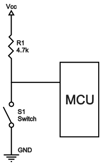
The idea is pretty much the same with FETs and other active devices. “Pull up” and “pull down” resistors are also used with switches. The resistance of the switch is also variable: either zero or infinite. In that case the resistor will pull the output of the switch all the way to either the positive supply voltage or to ground.

The values of the “pull up” and “pull down” resistors are usually calculated with Ohms Law. The circuit designer must have a value for the current that will flow in the resistor/transistor circuit. There will be several concerns for that value including the load impedance, the current rating of the transistor, the desired point of operation on the characteristic curves of the transistor, the amount of quescient current that is allowable/desirable, and others. Once that current value is determined, it is combined with the supply voltage in Ohms Law to find the value of the “pull up” or “pull down” resistor. R = E/I

If the current is significant a calculation of the power dissipation in the resistor should also be made: P = VI where V is the supply Voltage and I is the maximum current that can flow in the resistor. A general rule is to use a resistor that is rated at two times the power level that this calculation produces as a safety margin. Often (usually) the resistance value of the “pull up” or “pull down” resistor is made as high as possible in order to avoid the use of high power resistors.

Edward Alciatore
Beaumont, TX

Pull-up or down resistors does not refer to a type of resistor, but its function. Usually their purpose is to give a high impedance wire a known state. For instance, an output pin on a MPU may be an open collector output, capable of sinking a few mA. When it is activated, its state is grounded. When released, it floats, and has no definable state. In this case a pull-up resistor connected to the supply line would give it now a high level.

Pull-ups and pull-down resistors can be used in many locations, another example would be in an I2C buss. Read up on that, most descriptions will do a good job of explaining how it works.

Bill van Dijk
Carp, CANADA

The basic idea of a pull up or pull down resistor came from some logic families which had output pins connected to the collector of the output transistor stage. There was no internal connection to a power supply, so the output did not respond to logic states if no other connection was made. A suitable resistor was tied to the plus supply, so when the base of the transistor was held low the output went to the supply voltage (pulled up to the supply), and when the base of the transistor went high it would pull down the output to ground. The open collector allowed outputs to be wire ORed together saving parts. By connect several outputs to the same resistor, if any of them them went low it would pull the resistor down (an OR situation).

Values for these are usually suggested in the data sheets for the parts. To calculate a value get the max output current from the data sheet and use your supply voltage and ohms law to compute the smallest allowed resistor.

The idea has been extended to resistor networks which aid in driving high speed signals through long lines. A google on impedance matching and line driving will get you started on this variant.

Warren O Wilderson
Eagle Point

Pull-up and pull-down resistors once baffled me, too. Very often a device, say a 555 timer, will require a ground pulse to start a timing cycle. This means that one might install a momentary switch to ground to activate the timer. Well, if that pin on the chip is not already in some known state, it can behave differently each time it’s powered up. It may work as designed, it may not. If the wind blows from another direction, it may behave differently because it is “floating.”

Now, you could just connect it to the voltage that’s supplying the chip, but if you then forced that to ground, you’d have a short circuit and something is going to burn. If you have something held to supply voltage, say 12 volts, by way of a 10k resistor, it will sit there seeing 12 volts. If you then press the momentary button, the subject pin will see it as a ground and the 12 volts will cause 1.2 mA to flow momentarily.

So, you don’t have a short, the activating pin sees a ground pulse and starts working, and you won’t damage your circuit. Leaving any pin, even ones that specify “NC” (no connection) floating, may yield unexpected behaviors and not always the same “unexpected behavior.” In this case, it’s good practice to ground pins labeled “NC” either directly or by way of a “pull-down” resistor. If you always use a resistor, you minimize the chance of a short circuit even if you made a mistake in grounding the wrong pin. Hope this helps!

Brendan Ames
Albuquerque, NM

A pullup/pulldown resistor resolves a voltage ambiguity that may exist on a circuit node. These resistors are commonly used with transistors in digital switching operations.

A pullup resistor connects a node to logic 1 voltage (eg 5V) and a pulldown connects to logic zero (ground). For example, a bipolar transitor used for digital switching has a pullup resistor connecting logic 1 voltage to the collector node, i.e. the transistor switch output. When the transistor is off, no current flows through it or the pullup resistor. Ohm’s Law shows there can be no voltage drop across the resistor, hence the voltage on the collector must be at logic 1. When the transitor is on, current flows through the collector and pullup resistor. A voltage drop now exists across the resistor causing the collector voltage to drop below the level of logic state 1. The more current that flows, the bigger the voltage drop.

When a component is specified as open collector, the designer must supply the pullup resistor. This is the case for the I2C communication interface. The designer may choose a large pullup resistor to limit current and extend battery life. But there is a trade-off due to unavoidable stray capacitance (C) at the output. A large resistor will increase the RC time constant and slow down the response.

Mike Hasselbeck
Albuquerque, NM

Pull-up and Pull-down resistors are used to force an input signal line to a default level when there’s no external input applied. Typical pull-up values for Digital lines are between 1Kohm and 10Kohm, connected between the V+ line (i.e., +5 VDC) and the signal line. Pull-down resistors do the same thing, except they’re connected between V- (or GND) and the signal line, and are usually no smaller than 4K ohms.

To calculate the resistor size, you need to know how much current is going to flow INTO the line (pull-up) or flow OUT OF the line (pull-down). You typically don’t want more than 20 milliamps of current flowing through a pull-up nor do you want more than a few milliamps flowing through a pull-down. For +5V logic, pull-ups from 1K to 4.7K are sufficient.  You rarely see pull downs with +5V logic, but they are needed sometimes.  The power rating of the resistor is calculated using the (I^2) x R, and rarely goes above ½ watt.

You can connect a pull-up and pull-down in series, with the resistor junction connected to the signal line to form what’s called a receiver. You’ll typically find these on serial communication lines where the SIGNAL LOW value is a negative voltage. The pull-down resistor will usually be sized with the pull-up to create a voltage divider. You can find dividers with CMOS and +3.3V logic where you don’t want the HI to go above a certain value nor the LOW to go below 0V (GND).

Here is a good reference: http://www.resistorguide.com/pull-up-resistor_pull-down-resistor/.

Ken Simmons
Auburn, WA

To begin with, positive voltages are considered ‘up’ and negative voltages are ‘down’. A resistor connected to a positive voltage on one end and to a circuit element on the other end will be pulling the circuit element up to the positive voltage, if there is no current. If you want current to flow, you must figure how much and compute the resistance from: R=V/I; where V is the voltage drop across the resistor. Pullup resistors are often used with an IC that has an open collector output.

Pulldown resistors are most often used on the emitter of an NPN transistor. If the base of the transistor has a positive voltage applied, the negative voltage could be zero (ground). In any case, you need to know something about the circuit to compute the resistor value.

Russell Kincaid
Milford, NH

For a good discussion of pull-up and pull-down resistors, visit: https://www.electronics-tutorials.ws/logic/pull-up-resistor.html.

Jon Titus
Herriman, UT