Ms. Carrillo raised a question about a means of driving an LED from bright to dim, then reverse, and repeat. She further stipulated that it must be a non-IC-based circuit.
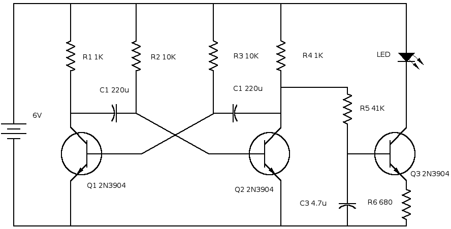
Since LED brightness is a nearly-linear function of its forward current, this suggests a triangle-waveform driver circuit. An examination of the information available on the internet for a transistor-based circuit uncovered a suitable circuit1 for which I have modified timing component values and added an output buffer, all of which is shown as Figure 1 below.
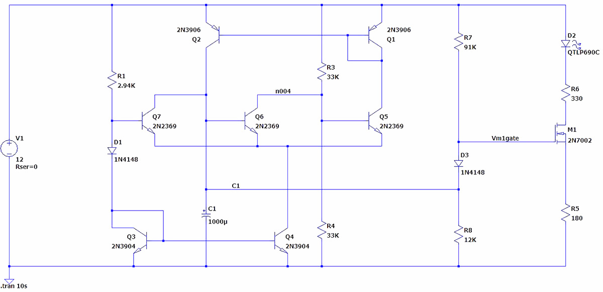
Figure 1: Schematic diagram
The circuit operates from a 12-volt source. It is comprised of two current-mirror elements Q1-Q2 and Q3-Q4, and a three-way differential comparator circuit Q5, Q6, and Q7. Current mirror Q3-Q4 functions such that the current drawn by the collector of output transistor Q4 will always be identical to the current supplied to the collector of input transistor Q3; a similar explanation can be made for the operation of current mirror Q1-Q2.
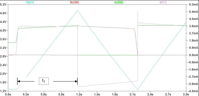
Figure 2: Charge C1
In the initial state, capacitor C1 is fully discharged. Upon application of power, R1 provides about 3.5 mA into current mirror Q3-Q4. Since the voltage at the upper end of C1 [V(C1)] is zero, Q6 is off. Q5, however, is forward-biased by the voltage divider R3-R4, thereby completing the circuit Q1-Q5-Q4, such that 3.5 mA is drawn by Q4 out of Q1. Because Q1-Q2 is also a current mirror, a current of 3.5 mA will be applied to C1 by Q2, whence V(C1) increases from zero. C1’s voltage increase is linear because the charging current is a constant value. See interval t1 in Figure 2 above.
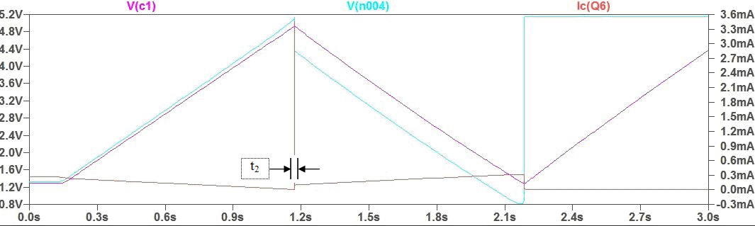
Figure 3: Switch
Transistor Q6 turns on at the point where C1 has risen to be equal to Q5’s base voltage. In its conducting state, Q6 steals current from R3, removing base drive to Q5, turning it off, thereby turning off current mirror Q1-Q2 whence charging current is removed from C1. See interval t2 in Figure 3; “V(n004)” is the base voltage at Q5.
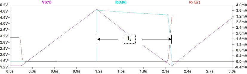
Figure 4: Discharge C1...
C1 discharges into current mirror Q3-Q4 via the base-emitter junction of Q6. This action provides base current to Q6, keeping it turned on until such time as the terminal voltage of C1 [V(C1)] falls below the base voltage at Q7 (set by voltage divider R1, D1 and Q3). At this point, Q7 begins to turn on, rapidly shutting off Q6. See interval t3 in Figure 4 above.
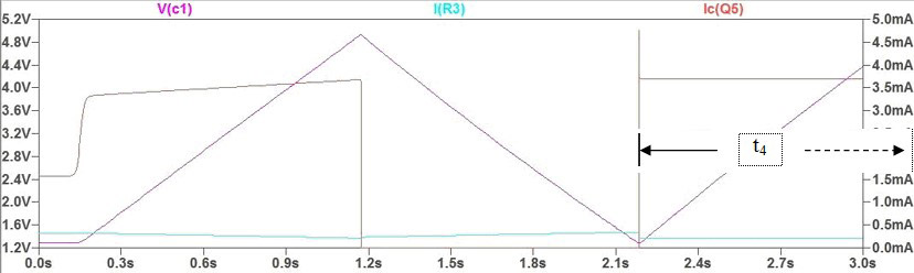
Figure 5: ... and repeat
Once Q6 is turned off, R3 can once again provide base current to Q5, turning it on; the cycle repeats. See interval t4 in Figure 5 above, being the same as interval t1 in Figure 2.
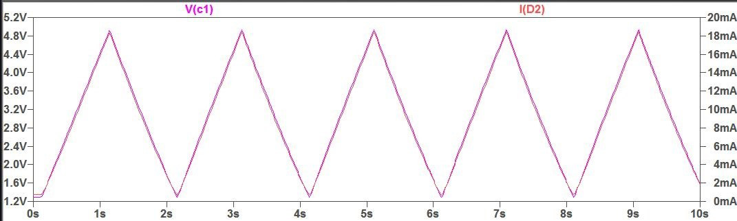
Figure 6: ... and repeat
Figures 2 through 5 show V(C1), the terminal voltage of C1, having a triangular waveform with a period of two seconds. This voltage is impressed upon the gate of MOSFET M1; diode D3 provides a DC voltage shift to better match the MOSFET’s characteristics. M1 drives LED D2 through current-limiting resistors R5 and R6, whose values have been chosen to enhance current linearity.
Figure 6 above shows the excellent match between drive voltage V(C1) and LED current I(D2). A linear drive current will produce a very nearly linear variation in light output; see Figure 7.
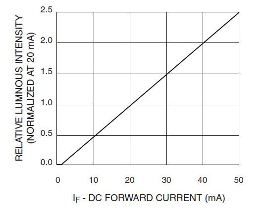
Figure 7: LED Luminosity vs Forward Current
Some words about the components used: M1 is shown as a 2N7002, which is a surface-mounted device, for which leaded part 2N7000 is a functional substitute. BS170 is another leaded version of this part. LED QTLP690C was a random choice from the LTSpice component library; choose your own with particular emphasis on current-vs-luminosity linearity. All resistors are 5% tolerance except R1, which is a 1% value. Given that the tolerance of C1 is probably not better than 10%, it would be wise to replace R1 with a 5K-ohm variable resistance to allow for adjustment if the timing is at all critical.
Current mirrors: Proper operation of a current mirror circuit requires that the silicon bodies of both transistors of the pair be at the same temperature. This is nearly impossible to achieve with discrete components, especially as in the present case when the power dissipated by the two transistors differs significantly, one from the other. Quad-transistor through-hole and surface-mount package equivalents of the 2N3904 and 2N3904 are available from Mouser and others; look for MPQ3904 and MPQ3906, respectively.
Ms. Carrillo did not specify the power of the LED to be driven. I assumed a small indicator, so that the maximum drive current provided by this circuit is just shy of 20 milliamperes. For larger, more-powerful devices, a larger MOSFET would be needed (with attendant modifications of the values of R5 and R6). A preferred approach in this case would be to use the drive current available at the drain of M1 as a means of modulating a multivibrator circuit, driving the large LED with a pulsed current whose pulse width varies according to the linear triangle-wave modulation. While such a circuit is beyond the scope of the present discussion, several, 2.3 have been found in the literature.
1 https://www.electronicspoint.com/forums/threads/7-transistors-triangle-wave-generator-650khz.264497/
2 See US Patent 3445788A, Camenzind, Pulse-Width Modulation Circuits (https://patents.google.com/patent/US3445788A/en)
3 See US Patent 3587002, Brown, Voltage-Controlled Transistor Multivibrator (https://patents.google.com/patent/US3587002)