In our last episode, we started a three part series on an Arduino-based handheld prototyper shown in Figures 1 and 2 (with the base artificially tinted blue so that it can be seen better).
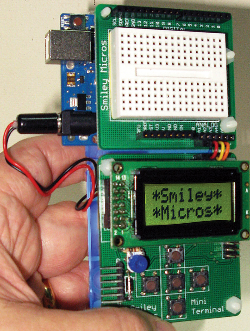
FIGURE 1. Arduino handheld prototyper front view.
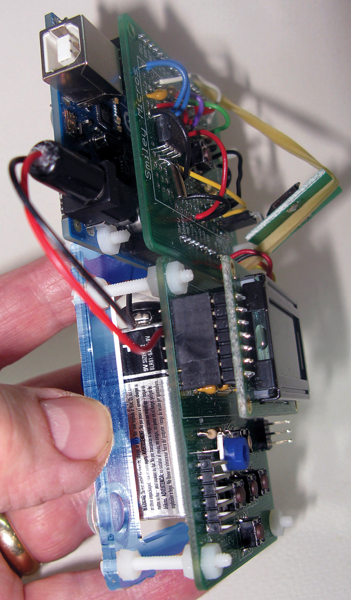
FIGURE 2. Side view.
The Arduino handheld prototyper — as the name implies — lets us develop prototypes that are portable (in our very own hand), and provides a bonus that is lacking in the stand-alone Arduino: It can accept user keypad input via pushbuttons, and provides the user with visual output via an LCD. This device consists of three main parts: an Arduino proto shield, an I2C mini terminal, and a base kit that holds them together. We introduced the I2C mini terminal in our last Workshop. Now, let's look in more detail at the software for that device.
Using The I2C Mini Terminal Software
The IMT (I2C mini terminal) software provides some simple and easy to use Arduino library functions that we saw last time in our mini_terminal_master demonstration program. We learned that by simply putting the MiniTerminal directory in the Arduino installation Libraries directory, we could use the Arduino IDE menu item 'Sketch,' followed by 'Import Library,' and then click the MiniTerminal entry that puts the header in our edit window:
#include <MiniTerminal.h>
We also add:
#include <Wire.h>
We are ready to start using the MiniTerminal functions from our Arduino. Doing this gives us the following functions:
// Print string to LCD at position p line l<br />
void mt_print(char* x, byte p, byte l);
// Print string from Program Memory to LCD at position p line l<br />
void mt_printPM(prog_char* x, byte p, byte l);
// Print an 8-bit number at position p line l<br />
void mt_print8BitNumber(uint8_t number, byte p, byte l);
// Tell the slave where to put the cursor<br />
void mt_setCursor(uint8_t p, uint8_t l);
// Turn the cursor on<br />
void mt_cursor();
// Turn the cursor off<br />
void mt_noCursor();
// Turn the cursor blink on<br />
void mt_blink();
// Turn the cursor blink off<br />
void mt_noBlink();
// Turn the display on<br />
void mt_display();
// Turn the display off<br />
void mt_noDisplay();
// Put the cursor in the upper left position<br />
void mt_home();
// Clear the LCD<br />
void mt_clear();
// Clear LCD line 0<br />
void mt_clear0();
// Clear LCD line 1<br />
void mt_clear1();
// Clear the LCD line<br />
void mt_clearLine();
// Get an 8-bit number<br />
// Name on line 0 in str<br />
// Number at end of line 1<br />
uint8_t mt_get8BitNumber(char * str,uint8_t start);
// Blocks waiting for a key to return<br />
uint8_t mt_getKeyWait();
// gets the key<br />
uint8_t mt_getKey();
These functions are all we need to write data to the I2C mini terminal LCD and to read the state of the five pushbuttons. Last time, we used the program mini_terminal_master.ino to test these functions. You can get that program and the MiniTerminal library from the downloads, at the end.
As usual, the 'Arduino-simple' library functions hide some less simple programming concepts that we will now look at in a bit more depth. You really don't have to look at this if all you want to do is use the library to drive the LCD and pushbuttons on the IMT. However, if you want to get a bit of a peek under the hood and learn some more advanced concepts, then let's have a go at it.
How The IMT Software Works
In the section above, we saw several commands beginning with mt_ including: mt_get_key(); mt_home(); mt_clear(); mt_print();, etc. Each of these functions uses the Arduino “Wire” library to communicate to the IMT via the I2C bus.
[Time for a rant: Naming an I2C library 'Wire' is probably one of the dumbest ideas ever, especially since the base Arduino code uses the 'wiring' library that is totally unrelated to the Wire library. Both are dumb
names but they are great libraries, so let's accept them and move on ...]
Let's look at some of these functions in more detail, beginning with how we get the communications started. We see in the MiniTerminal.h module that we have defined the constant SLAVE as the number 42 [for the simple reason that it is the meaning of life, the universe, and everything ... at least according to The Hitchhicker's Guide to the Galaxy]. It really doesn't matter what number we choose, as long as both the Arduino master and the IMT slave agree as to what that number is.
We get the I2C ball rolling by running Wire.begin() in the setup() function. How simple is that? [This function does all the complex low level stuff to set up the ATmega328P on the Arduino to use the resident I2C peripheral.]
The Wire library provides us with several functions that let us request information from the slave, and to read from and write to the slave. In the mini_terminal_master.ino setup() function, we see:
void setup() // one time functions to get started<br />
{   <br />
  Wire.begin(); // join i2c bus (address optional for master)<br />
   <br />
  mt_clear(); // Clear the LCD<br />
  mt_print(Hello,0,0); // Print Hello on line 1<br />
  mt_print(world,0,1); // Print world! on line 2<br />
}
Calling these functions results in the IMT displaying the text shown in Figure 3.
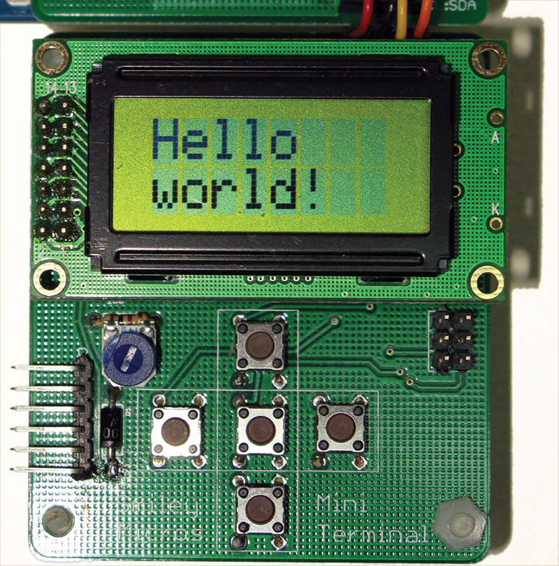
FIGURE 3. Say 'Hello world!'
After this, we enter the standard Arduino loop() function that asks the IMT slave every 100 milliseconds if any buttons have been pressed; if it returns a button different from the last button it returned, then the master tells the slave to display that button name in the top line of the LCD display as shown when the user presses the center button in Figure 4.
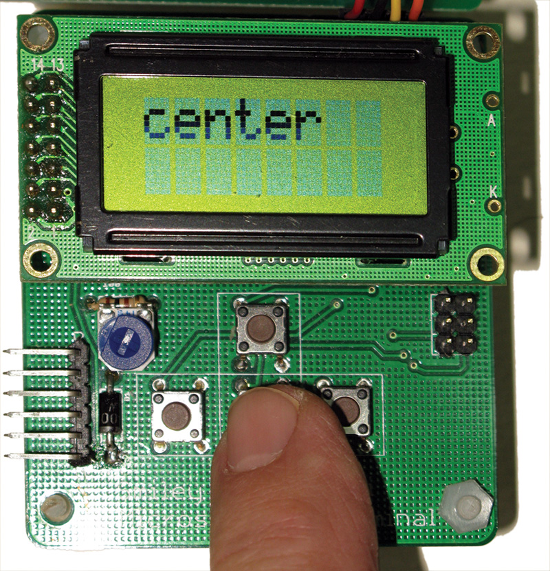
FIGURE 4. Center button pressed.
The 'mt_' functions are all very similar in that they each send an I2C request to the slave in a pre-arranged format such as shown here:
// Tell the slave where to put the cursor<br />
void mt_setCursor(uint8_t p, uint8_t l)<br />
{  <br />
    Wire.beginTransmission(SLAVE); // start buffering<br />
    Wire.write("LCD"); // command for the LCD<br />
    Wire.write(LCD_SET_CURSOR); // command name<br />
    Wire.write(p); // cursor position<br />
    Wire.write(l); // cursor line      <br />
    Wire.endTransmission(); // send the buffer<br />
    delay(DELAY); // wait a moment to complete  <br />
}}
The function begins by calling the Wire.beginTransmission function that opens up some stuff (you never have to see) to buffer what you are going to send with the following statements. The write commands put stuff into that temporary buffer and the Wire.endTransmission function sends the data to the slave.
In the case shown above, the slave sees 'LCD' and uses that to select the LCD case statement. The LCD case statement then sees the 'C' which causes it to call the function that handles the cursor setting. That function then sees the 'p' and 'l' parameters and uses those to set the cursor to the indicated position and line.
Another *#!@%&*$! Bug!
As usual, everything is so easy that I had to spend a full day debugging the darn thing! It worked like a champ on the Arduino Diecimila but like a chump on the Arduino Uno. First, I did a bunch of Googling and found a plethora of folks who had problems with I2C code that worked on older Arduinos but not on the Uno. Unfortunately, none of their solutions worked for me. I did the next logical thing and added debugging statements that sent information out the USB serial port between each Wire call such as:
Serial.println("Before call to endTransmission");<br />
Wire.endTransmission();<br />
Serial.println("After call to endTransmission");
This code started working ... THAT IS NOT SUPPOSED TO HAPPEN! What is supposed to happen is that I should see a bunch of 'before' and 'after' strings in the serial monitor. Then, the last 'before' I get that isn't followed by an 'after' should indicate the function where the code failed. The code no longer failed.
I started commenting out my Serial.println statements and got to the point that I found one that made things work if it had more than a certain number of characters, but not work if it had less than that number of characters. Well, that is just crazy. This is the point in debugging where you find out if you are really cut out for this stuff. If you start screaming and throwing things, maybe you should consider another pursuit. If you get excited because you are cornering a bug, then proceed with my blessings.
I figured that the serial functions must be providing time for something that was happening in the background. So, I started sprinkling around delay() functions until I hit on putting a delay after the endTransmission function — suddenly the program worked without the serial functions.
This, of course, made sense in retrospect since the endTransmission function is where the buffered characters are actually sent out the I2C bus. This means that the I2C peripheral has been told to go do some stuff, and the AVR core gets back to what it does while the peripheral does what it does. Previously, the I2C finished its job before I called it again, but not so with the Uno. On the Uno, there wasn't enough time for the stuff to get transmitted before I was calling another Wire function, so it somehow locked things up.
I could go and look into that Wire code since I have the source and probably find where it is locking up, but why bother? I found that adding a delay of five milliseconds got things working on the Uno, so I figured why not just move on and leave the Wire code to the experts?
Storing IMT Strings In Cheap Memory
Our last Workshop introduced the concept of using program memory to save in the SRAM and we saw how to use the p_string. Now, we'll repeat a bit of that and go into a lot more details for those who really want to know. One of the first things you may notice in the mini_terminal_master.ino application is the section beginning:
// Store strings in program memory<br />
p_string(Hello) = "Hello";<br />
…
This uses a macro p_string located in the MiniTerminal.h header file that lets us store strings of data in program memory. For microcontrollers, SRAM is used to run the program and tends to be precious and small, while the program memory tends to be stored in a cheaper and larger type of memory such as data Flash in the AVR. [For instance, the Arduino using an ATmega328P has 2K SRAM and 32K program memory.] However, the C (and C++) compilers gcc and g++ (used by the Arduino) will put character strings in the expensive limited SRAM unless we take special measures to put it in the cheap abundant program memory.
We want to save the SRAM as much as possible for our program to use when it is running, so we go to some trouble to put those strings in data Flash. The version of these compilers used by the Arduino has some special features that allow us to store and retrieve strings in the cheaper program memory. These features are somewhat arcane but let's take a look at them here — just remember that it isn't necessary for you to understand this to use it. As I said last time, it might seem a bit overkill to go to all that trouble since [in this example] we are only using a few short words, but in a real world application you might want to present a lot of information to the user, so it is good to have an option that won't run you out of memory.
The C compiler that is used by the Arduino has some things added to it that helps it compile code optimized for AVRs. One thing it provides is a set of tools for using the data Flash that calls program memory and uses the identifier: PROGMEM. The features are located in the header: pgmspace.h file.
You can get detailed documentation about this from the avr-libc manual that you may be surprised to learn is already loaded on your computer if you have the Arduino IDE installed. On my computer, I have the Arduino IDE on the C drive, so my copy is located at: C:\Arduino-1.0.4\hardware\tools\avr\doc\avr-libc.
If you want to move beyond the Arduino, this manual is one place to learn about the sorts of tools that underpin the Arduino. Open the MiniTerminal.h header file and you will see that it has:
#include <avr/pgmspace.h>
We need this so that we can define the p_string macro:
// Use to hide complexity of locating data in program memory<br />
#define p_string(text) prog_char (text)[] PROGMEM
A macro is a string of characters that follow a #define — like the p_string(text) above. The compiler substitutes the characters that follow the macro; in the above case, it’s prog_char (text)[] PROGMEM for the macro characters that follow the #define. It also lets us create a sort of variable for the macro such as the 'text' in the p_string macro, and writes the contents of this variable to the location of the 'text' in the macro substitution string. This is less complicated than it sounds. For example:
p_string(Hello) = "Hello";
As shown in Figure 5,
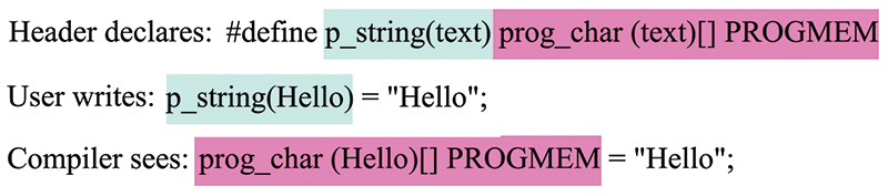
FIGURE 5. The p_string macro in action.
the #define instructs the compiler to do the following:
For: p_string(text)
Substitute: prog_char (text)[] PROGMEM
So when the compiler sees: p_string(Hello)
It substitutes: prog_char (Hello)[] PROGMEM
And it leaves the text that follows alone: = "Hello";
Thereby translating: p_string(Hello) = "Hello";
To: prog_char (Hello)[] PROGMEM = "Hello";
So, what we have done is create an Arduino-simple macro that translates: p_string(Hello) = "Hello";
To the less simple: prog_char (Hello)[] PROGMEM = "Hello";
The first version that I'm calling Arduino-simple is something that I think we can easily remember to use to store strings in program memory. The compiler-translated version of that line is what is needed by the compiler to actually store "Hello" in program memory. Of course, you could use the second version without having to use the macro, but frankly, I think I'm more likely to remember that I can store a string in cheap memory with the p_string(mystring) = "mystring'; than the version the compiler wants. We use this concept with the mt_print function as follows:
Store strings in program memory:
p_string(Hello) = "Hello";<br />
p_string(world) = "world!";
Then print them with:
mt_printPM(Hello,0,0); // Print Hello on line 1<br />
mt_printPM(world,0,1); // Print world! on line 2
The words 'Hello' and 'world!' appear on the LCD as shown in Figure 3. To me, that IS Arduino-simple.
Under the hood, some more complex things are going on so that we can use the strings stored in program memory. In the MiniTerminal.cpp module, we have the mt_printPM function:
void mt_printPM(prog_char* x, byte p, byte l)<br />
{<br />
  mt_setCursor(p,l);<br />
 <br />
  for (int i=0; i < 8; i++) {<br />
    buffer[[i] = (char)pgm_read_byte(&x[i]);<br />
  }<br />
  buffer[9] = '\0';
  Wire.beginTransmission(SLAVE);<br />
  Wire.write("LCD:");<br />
  Wire.write(buffer);<br />
  Wire.endTransmission();<br />
  delay(DELAY);  <br />
}
In this function, we are using some things from avr-libc (a set of open source tools that the Arduino uses when it compiles programs). We see that we are using the datatype from avr-libc: prog_char* x — a pointer to a string named 'x' in program memory — as a parameter to the function. In the function body, we see that we are using that string as an array and reading it into a buffer (temporarily using SRAM) one byte at a time with pgm_read_byte also from avr-libc. We read eight bytes since that is how many characters the LCD can hold. We then terminate the buffer with '\0' — the NULL character that tells C that a string has come to an end.
Now, we can use that temporary buffer to send the bytes to the MiniTerminal and have them displayed on the LCD. All the IMT sees is the stream of bytes; it knows nothing about how they were stored by the sender. If you think this is complicated, you should take a look at the PROGMEM stuff in avr-libc to see what is even deeper under the hood there.
The p_string macro we are using provides two layers of simplification above the truly difficult stuff in avr-libc. If we just want to use the LCD and don't really care how it works, then using these layers makes sense. If we can use the computer to do the hard stuff to simplify our lives, why not do so?
So, this takes us from our last Workshop's Arduino-simple high level view of how to use the IMT to the intermediate level libraries, and hints at the further complexities in the next layer down in avr-libc and the Wire library. You should have some further insight about the software abstraction process that puts progressively simpler layers on top of the complex underlying code, then lets the computer deal with the hard stuff while allowing the user to get the job done (wasting as few brain cells as possible).
Some guru types are going to try to make you feel guilty about doing this the easy way, claiming you ought to use real C (or assembler or whatever) or go home. Just smile at them, while you actually make things work using the best (read simplest) tools available.
Building The Arduino Handheld Prototyper
The Arduino handheld prototyper consists of three main parts, two of which we have already seen. First, there is the Arduino proto shield that we looked at in great detail beginning in Workshop #53. The second part is the IMT that we began looking at in our last episode. The third part is the base kit (Figure 6) that ties together the first two parts, giving us an Arduino, a proto shield with a mini breadboard, and an IMT with an 8x2 character LCD and five pushbuttons that (taken all together) can be used to prototype devices.
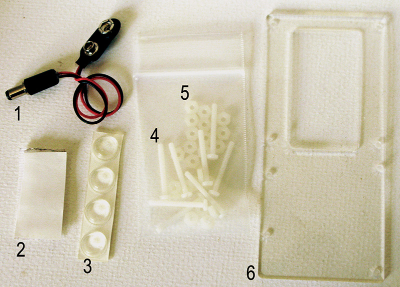
FIGURE 6. Arduino handheld base parts.
| PN |
#/kit |
Part Name |
| 1 |
1 |
Nine volt battery snap with 5.5 x 2.5 mm barrel |
| 2 |
1 |
Velcro strip |
| 3 |
4 |
Bumpers |
| 4 |
7 |
1" nylon bolt #6 |
| 5 |
21 |
Nylon nuts #6 |
| 6 |
1 |
Acrylic Base |
FIGURE 6. Reference Guide.
The base kit has a plastic base board, lots of nylon nuts and bolts, a nine volt battery connector, some Velcro™ to attach the battery, and some bumper feet. [You can get the Arduino proto shield, the IMT, and the handheld prototyper from the Nuts & Volts webstore.]
The components in Figure 6 are intended to use with both the older style Arduinos and the newer Uno R3 with expanded connections. We have sufficient nylon nuts and bolts to build either style, but here we'll see the Uno R3 being built. Figure 7 shows the plastic base with the bolts in the holes held in place by nuts (also the rubber bumpers are on the bottom, but show through the clear plastic).
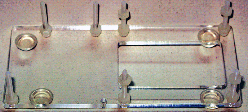
FIGURE 7. Base with bolts.
Note that there is no bolt in the hole that corresponds to the Arduino hole directly next to the battery connector. This is because there is no corresponding hole on the Arduino proto shield (which doesn't matter since the shield is mostly held in place by all the male/female pass through connections and the other bolts). We see the Arduino placed on the bolts in Figure 8.
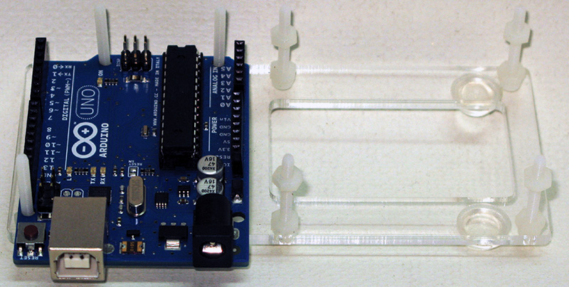
FIGURE 8. Arduino on base.
The two bolts at the top of the photo should have nuts added to hold down the Arduino. The bolt nearest the USB (in Figure 9) may have a nut added on the older models, but in the Uno R3 the extra connections are too close to allow it.
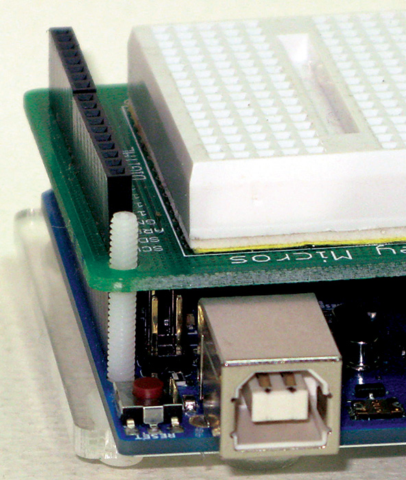
FIGURE 9. R3 bolt.
We can see the Arduino proto shield added in Figure 10.
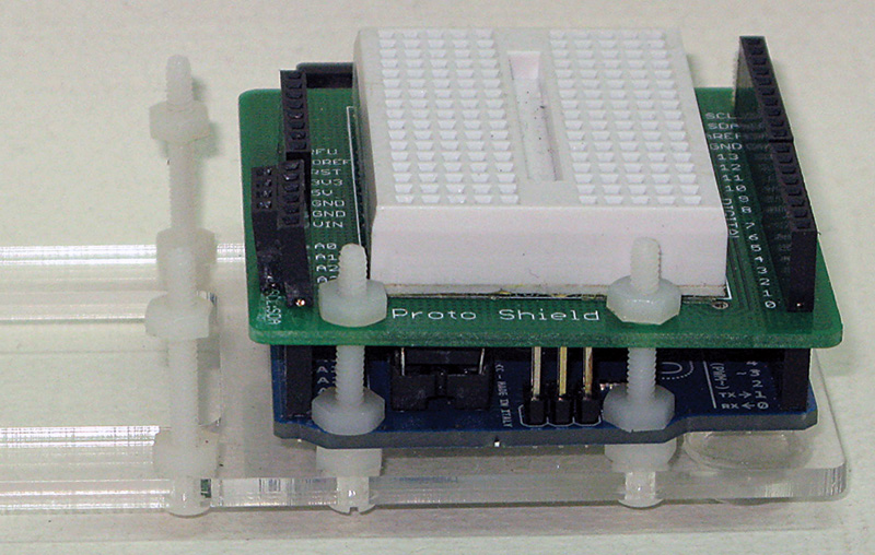
FIGURE 10. Arduino proto shield on base.
Note that the nuts are on top only, since they are not needed underneath the PCB to support the board since it is already supported by the male/female shield connections.
We saw in Figure 7 that there is an extra set of nuts about three-quarters of the way up the shaft of the bolt. These are used to support the IMT as shown in Figure 11 (with the LCD removed).
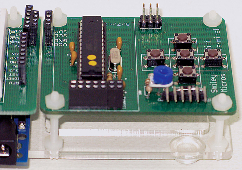
FIGURE 11. I2C mini terminal PCB bolted on base.
I2C Connection For Old Arduinos Versus New Arduino Uno R3
There are two types of I2C connections for the Arduino (at this writing). For the newer Arduino Uno R3, we wire the four-pin female connectors straight onto each other as shown in Figure 12.
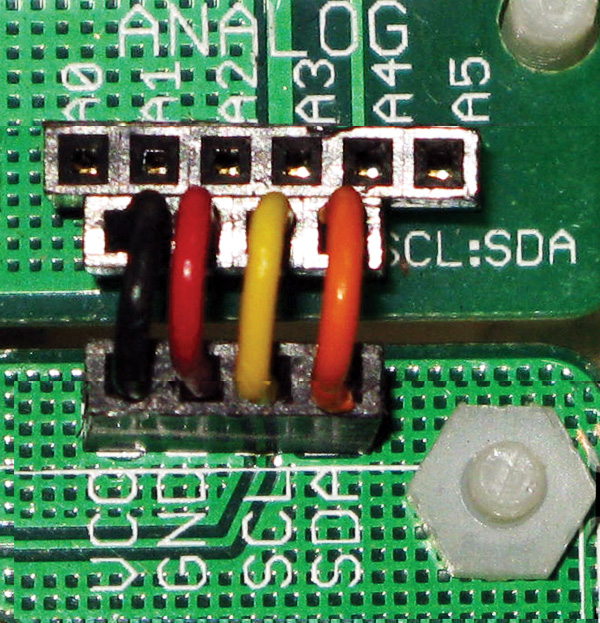
FIGURE 12. I2C R3 connection.
For the older non-R3 Arduinos, we connect analog A4 to SDA, and analog A5 to SCL as shown in Figure 13.
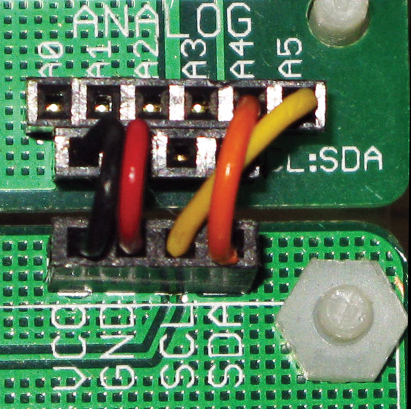
FIGURE 13. I2C non-R3 connection.
Notice that the I2C wires cross each other in Figure 13 but are parallel in Figure 12.
Finally, we add one side of the Velcro to the bottom of the IMT PCB and the other to a nine volt battery. Then, we add the snap connector to the battery and the barrel connection to the Arduino as shown in Figure 14.
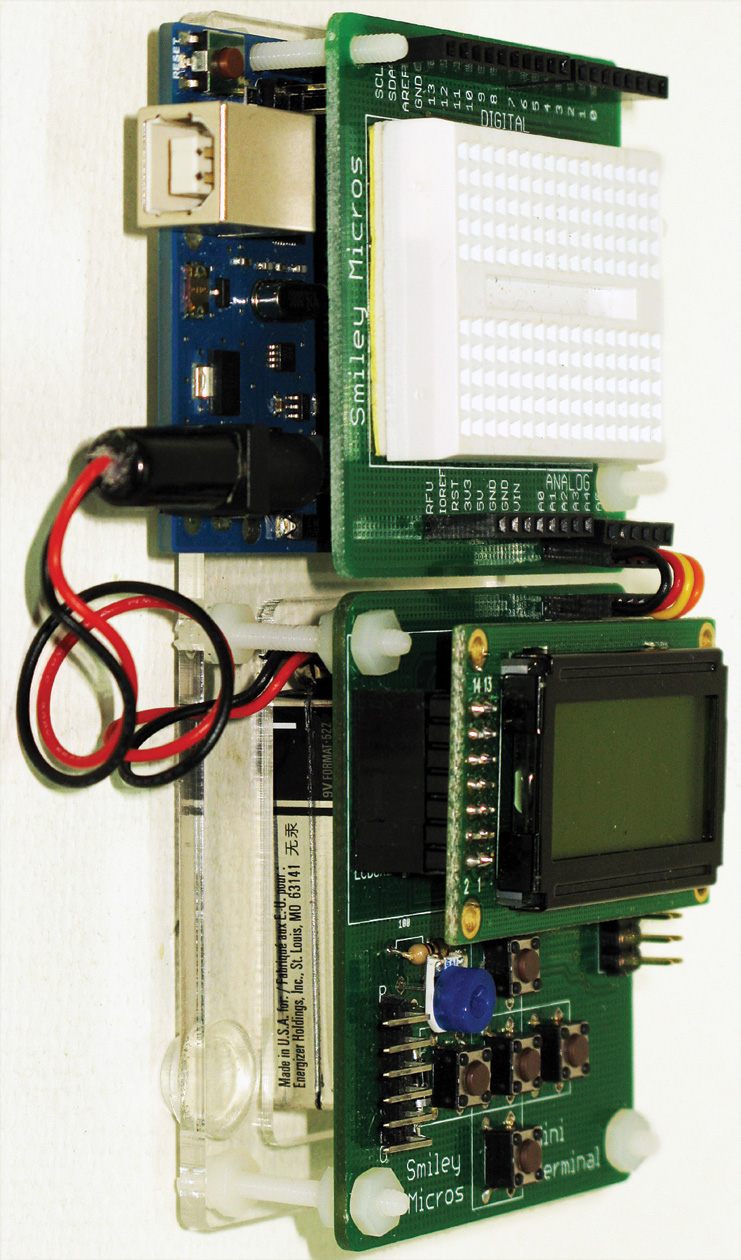
FIGURE 14. Assembled with battery.
Be sure to unplug the battery from the Arduino when you aren't using it since the Arduino may be running (you can't see the 'on' LED under the proto shield) and you will deplete the battery.
Wrap-Up
The main goal for this device is to help you prototype your own designs. I'm always amazed at the stuff folks are doing, and I'm looking forward to hearing from readers who use this device to see what sorts of things are developed.
Last time, I promised to discuss how to create a fresh air controller for a castle, but I'm putting that off till next time when we will apply the handheld prototyper to a practical project. This is a perfect application for our new tool, even if you don’t own a castle. NV
Downloads
What’s in the zip?
mini_terminal_master.ino
Other source code files