That Uses a “Magic Wand,” “Invisible Spring,” and “Tri-State” Electromagnetic Switch
The game of Tic-Tac-Toe has been around for centuries. With all the electronic games kids play with today, it’s unlikely that you’ll see “gamers” stampeding to play an old pencil and paper game. So, let’s update the old classic a bit to make it a little more attractive to the “blue screen” generation – young and old.
TIC-TAC-TOE
I taught my two grandsons (Johnny/Charlie) how to play Tic-Tac-Toe this year. Big mistake! Now, every day, I get “Grandpa, let’s play Tic-Tac-Toe.” Since they like this simple game of Xs and Os so much, I thought I’d design and build them a special electronic version.
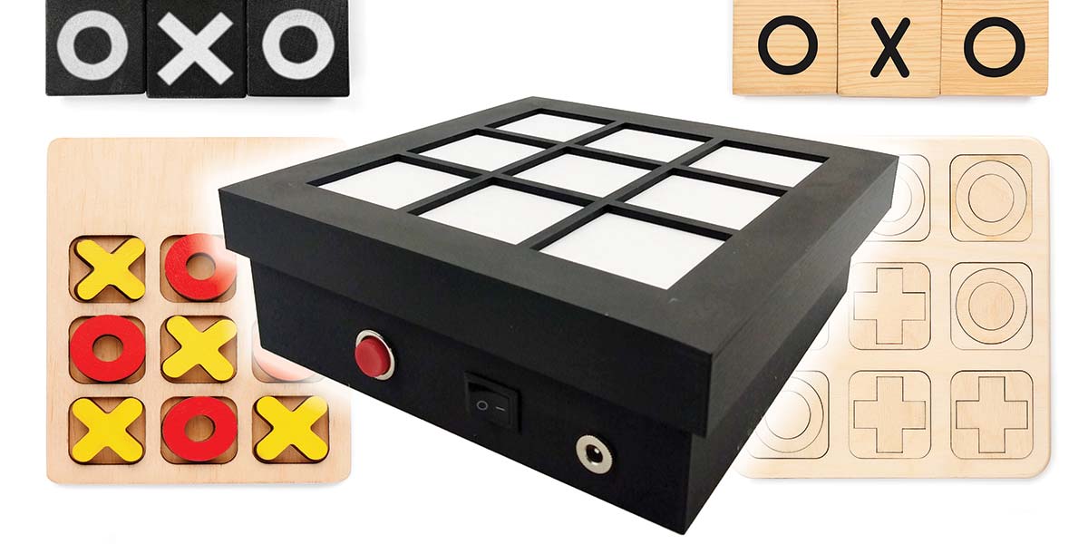
I decided to add a little twist to the game by making a couple of “magic wands” that they can hover over each of the nine squares and have an X or O magically appear on the board — depending on which wand they picked.
This was a challenging project, but I was able to incorporate my “tri-state” electromagnetic switch, “invisible spring,” and “magic wands” into the game.
So, power up your soldering iron and 3D printer! Let’s get started!
HOW IT WORKS
If you’re like me, you have a bunch of old ICs sitting in a bin somewhere just waiting for the right project. A good example is the 74LS47N IC (decoder/driver) shown in Figure 1.
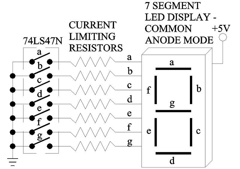
Figure 1.
I thought, why not park seven regular 5 mm through-hole type sof LEDs on the outputs of the 74LS47N, and arrange the LEDs so they can display just two letters: O and X.
To switch between an O or X on the display, I employed two Silicon Controlled Rectifiers (SCRs). SCRs are really simple devices to operate. If you place a positive voltage at the gate terminal (G), the SCR turns on and current will flow from the anode (A) terminal to the cathode terminal (K). The neat thing about SCRs is the fact that the device will stay turned on even if the gate voltage is removed — Latch. The only way to turn the SCR off is to temporarily remove the voltage (i.e., momentary switch) from the anode (A) terminal.
Here’s how the circuit works (see Figure 2).
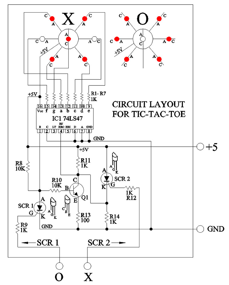
Figure 2.
Initially, with power applied to the circuit, SCR1 is off. This allows pull-up resistor R8 to pull input pin 1 of the 74LS47N high (5V). In turn, this turns transistor Q1 (NPN) on. Consequently, the collector of Q1 and pin 4 (BI-Blanking Input) both see a low at the same time, thereby blanking the LED display. This is the normal startup condition of the circuit once power is applied to the game.
Now, if SCR1 is triggered first, it will sink pin 1 (B) to ground and at the same time shut off transistor Q1. In turn, the collector of Q1 and pin 4 (BI) both switch to a high state. Therefore, to display the letter O, a low on pin 1 (B) and a high on pin 4 (BI) tells the 74LS74N decoder chip to switch off the ‘g’ segment (pin 14) and turn on the a, b, c, d, e, and f segments.
If you look at Figure 2 again, you’ll see that the g segment (pin 14) in the circuit is wired to the center LED. In other words, the above sequence of events will turn off the center LED and display the letter O with the remaining segments turned on.
Conversely, if we want an X to be displayed on the LEDs, we activate SCR2 by applying 5V to the gate terminal; this places a high at pin 4 (BI). Now, as long as SCR1 hasn’t turned on, there will still be a high on pin 1 (B) from the initial power-up sequence mentioned above. A high on pin 1 (B) and a high on pin 4 (BI) will force the 74LS47N to respond by turning on the g segment and turning off the c and f segments which, of course, turns off the two LEDs attached to pin 11 (c) and pin 15 (f).
Notice how the two switches SCR1 and SCR2 determine whether an O or X will appear on the LED display. In a nutshell, here’s the sequence of events required to display the correct letter on the seven LEDs — assuming pin 2 (C), pin 6 (D), and pin 7 (A) are tied to ground (low):
SCR1 (off) - A high on pin 1 (B) and a low on pin 4 (BI/RBO) = LEDs off.
SCR1 (on) - A low on pin 1 (B) and a high on pin 4 (BI/RBO) = O.
SCR2 (off) - A high on pin 1 (B) and a low on pin 4 (BI/RBO) = LEDs Off.
SCR2 (on) - A high on pin 1(B) and a high on pin 4 (BI/RBO) = X.
If you look up the function table for the 74LS47N IC, you’ll see the logic behind the above sequence. Figure 3 shows the important section of that table.
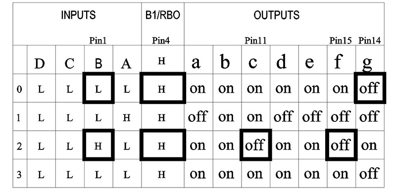
Figure 3.
It’s also important to mention here that I set up the 74LS47N and LEDs in the “Common Anode” configuration. This means that all the LED anodes (A) are connected together and then wired to a 5V supply connection. In other words, to turn on any LED, its cathode terminal (C) must be switched from a high to a low (active low); refer to Figure 1 again.
Okay, everything seems to be working according to plan. Now, how do we activate SCR1 and SCR2 with a magic wand?
Take a look at Figure 4.
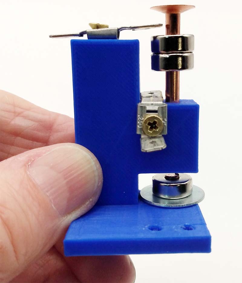
Figure 4.
It shows the mechanism I came up with to trigger SCR1 or SCR2 with a wand.
Looking at Figure 5, you can see how the magnets, printed circuit board (PCB), housing assembly, and the wands all work together.
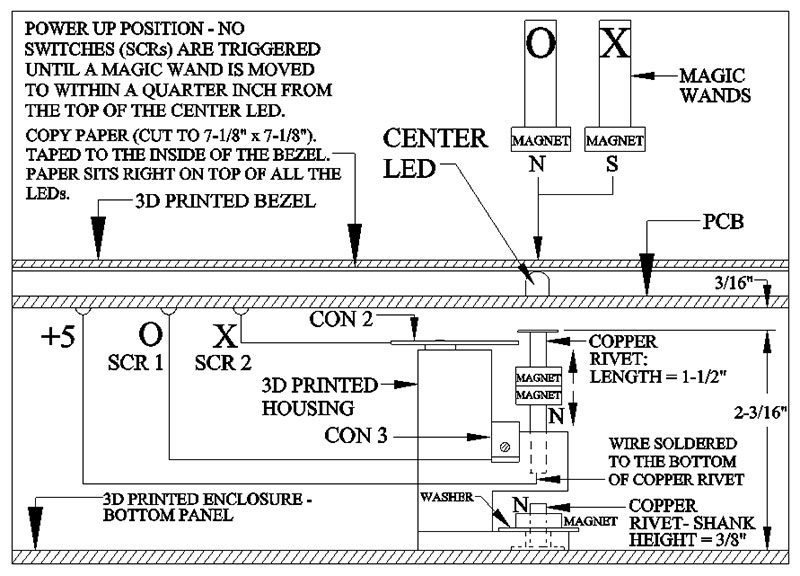
Figure 5.
It takes five small neodymium magnets and two copper rivets for the whole system to function properly. The two magnets kind of act like a single pole double throw (SPDT) switch. If the O wand (magnet) moves close to the top magnet and it has the same polarity (north-north), it will push the top two magnets downward towards the bottom electrical connector CON 3.
This action connects the five volt supply from the PCB to the bottom of the copper rivet (non-magnetic, but electrically conductive), and finally to the electrical connector CON 3; this triggers SCR1.
In turn, this forces the LEDs to display the letter O. On the other hand, the X wand (magnet) with an opposite polarity will attract the top magnet and pull the magnets upwards towards the top electrical connector CON 2. Consequently, SCR2 will trigger, and the LEDs will display the letter X. In other words, depending on the wand’s magnetic polarity, it will either push the two magnets up or down, thereby turning on SCR1 (O) or SCR2 (X).
Figure 6a, 6b, and 6c show the different modes of operation more clearly.
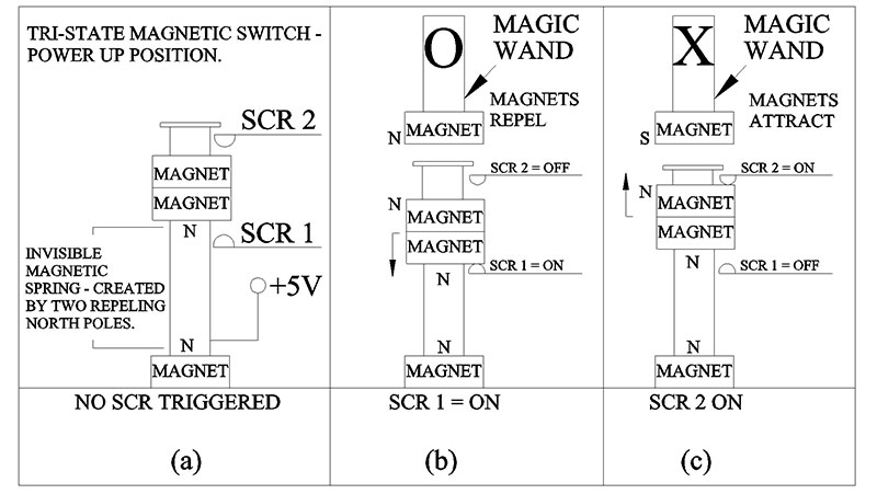
Figure 6a, 6b, and 6c.
Figure 7 also helps to visualize how the switches, magnet assembly, and PCB work together as a unit.
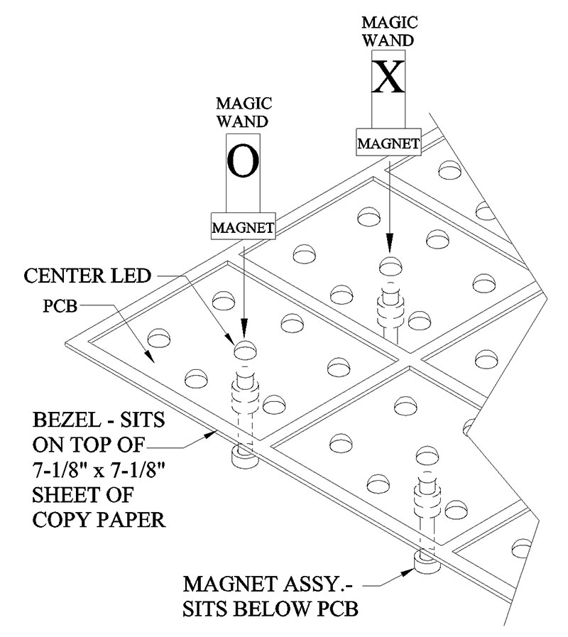
Figure 7.
THE INVISIBLE SPRING
Hold it right there! What’s keeping the magnets centered between the two electrical connectors? This is where the “invisible spring” makes its appearance. If you add another magnet to the base of the housing with the same polarity as the magnet underneath the top magnet, they will repel each other, thereby creating an invisible spring.
I found that if I used 1/2” diameter neodymium magnets, the correct distance between the top two magnets and the top surface of the base magnet comes to 1-5/16”. This distance makes the magnets “float” in between the two electrical connectors.
Notice how the floating magnets create what could be described as an electromagnetic “tri-state” switch: SCR1 = ON or SCR2 = ON or both SCRs = OFF. This is not like your standard SPDT switch. I needed to make sure both SCR switches were off when the circuit is powered up. Otherwise, you would have an X or O appear on the LED display before the game even starts.
CONSTRUCTION
These instructions of how the circuit and magnet assembly works apply to only one square on the Tic-Tac-Toe game. The game requires one magnet assembly and one circuit like the one in Figure 2 for each of the nine squares. Therefore, you’ll need a total of 27 magnets plus three magnets for each wand: 33 total.
Figure 8 shows the PCB I designed.
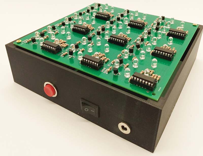
Figure 8.
You can get the CAD drawings and/or Gerber files from the article downloads. The 3D printer files (.stl) for the wands, housing assembly, enclosure, and top bezel are also available there.
Figure 9 shows where the 3D printed magnet assembly is permanently attached to the bottom of the enclosure.
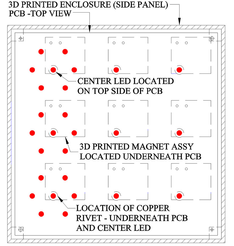
Figure 9.
Figure 10 shows the PCB, power, and reset switches assembled inside the enclosure (black box). Notice how both switches are wired in series.
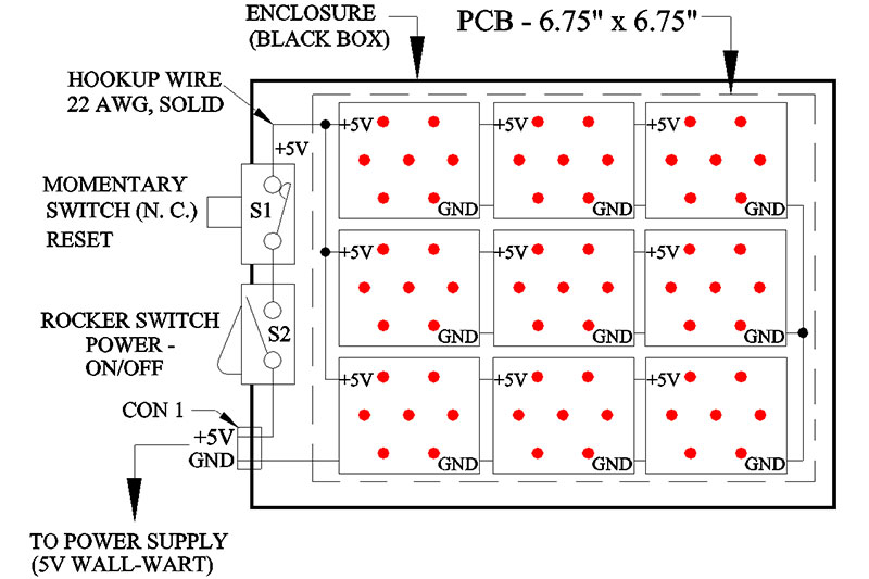
Figure 10.
Figure 11 shows a top view of the 3D printed bezel that sits on top of the enclosure.
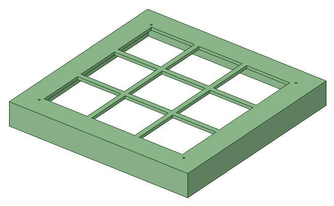
Figure 11.
Figure 12 is a photo of the 3D printed wands.
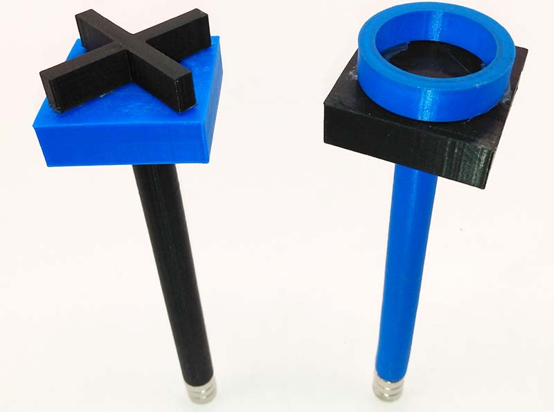
Figure 12.
TIME TO HAVE SOME FUN
Playing the game is easy. Just plug in the 5V power supply (wall wart) into the front panel connector (CON 1).
Next, turn on power switch S2. Now, move either wand (X or O) in a downward motion over the center of any square and, depending on which wand you’re holding, the square will display an X or O.
To ‘reset’ the game so all the squares are blank, just hit the momentary switch S1 one time and all the SCRs will reset to the off state. The power button S2 turns the game completely off.
TIPS
- IMPORTANT: All LEDs must sit perfectly flat on the PCB. If any one of the LEDs sits too high off the surface of the PCB, it will affect all the surrounding LEDs by not shining through the sheet of copy paper. All the IC sockets must also sit flat on the PCB so they are below the height of the LEDs.
- Scotch tape is helpful to hold down components on the top side of the PCB while you’re trying to solder from the other side of the board.
- When you order PCBs, make sure you select 2 oz copper. One ounce copper pads and traces peel off too easily from the heat of a soldering iron.
- TESTING: Populate only one of the nine circuits on the PCB with all the components and then test every 74LS47N IC that you purchased is functioning properly. It wouldn’t hurt to breadboard the circuit first and then check all your components (ICs, SCRs, etc.) for defects. De-soldering components on a PCB is not a lot of fun!
- Neodymium magnets are very strong. Unfortunately, they are also very brittle. Make sure when you separate the magnets they don’t snap together again and break — trust me, I know!
- Like most magnets, neodymium magnets are also attracted to iron (ferrous) and steel based components. Therefore, don’t substitute any for the copper rivets, brass screws, or brass connectors used in this project.
- Don’t use any resistors in this project that aren’t ‘carbon composition’ resistors. I was a little surprised to find the neodymium magnets were attracted to the internal composition of some through-hole resistors.
- Soldering wires to solid copper rivets can be a little difficult because copper acts like a heatsink. The trick is to file the end of the rivet a little bit and then hold the soldering iron tip on the end of the rivet for about 7-10 seconds. You’ll notice the solder will wick itself to the wire and the rivet.
- To reduce the chance of short circuits, put two coats of nail polish on the head of each copper rivet. Remember, the head of the copper rivet is only 3/16” away from the bottom (solder side) of the PCB. Finally, rather than having to solder nine wires to the PCB, just solder all nine copper rivet wires together and then run one wire to any +5V connection on the PCB.
- 3D printers are not perfect when it comes to dimensional accuracy. Therefore, I purposely made a few holes a little bit smaller to allow for the differences in printers. If necessary, this will allow you to drill out a smaller hole to get things to fit. On the other hand, you may find that the hole for the short copper rivet (3/8”) is a little loose. Once again, use a piece of Scotch tape on the bottom of the housing to hold it in place. Leave the tape in place because it will not affect the 3D printed housing (level) or operation of the game.
- Shipping rates have gone through the roof lately. One supplier wanted $50 to ship a 10 oz package. Just be beware before you click on the ‘Buy’ button.
- Just like shipping rates, components have gone up in price too. I was shocked to see the price for one 74LS47N IC range from $.40 cents to over $5. Although I shopped around to get a good price on all the components in this project, you may have better luck.
Note: When shopping for the copper rivets, the O.D. must be .156” (3.96 mm) to fit and slide inside the magnet hole.
FINAL WORD
Although designing this project was fun and challenging, it was also frustrating at times. The 36 hairs I had left on my head are now gone (bye bye!). I would love to hear any comments you have about this project. You can post them on this article’s website page. NV
| QTY |
ITEM |
DESCRIPTION |
PART NUMBER |
SOURCE |
| 99 |
R1-R7,R9,R11,R12,R14 |
Resistor, 1K, 5%, 1/4W, Through Hole, Carbon Composition |
25M8365 |
NEWARK |
| 18 |
R8,R10 |
Resistor, 10K, 5%, 1/4W, Through Hole, Carbon Composition |
25M8371 |
NEWARK |
| 9 |
R13 |
Resistor, 100 ohm, 5%, 1/4W, Through Hole, Carbon Composition |
25M8374 |
NEWARK |
| 9 |
Q1 |
Transistor, 2N2222A, NPN |
610-PN2222A |
MOUSER |
| 18 |
SCR1,SCR2 |
SCR, Silicon Controlled Rectifier, 1.2A, 600V |
X0205MA 1BA2 |
ARROW |
| 63 |
LED1-LED7 |
LED, Red 640 nm, Through Hole, 5 mm Dia., 8.7 mm Height, Clear Dome (Ultra-Bright) |
604-WP1503SRC/J4 |
MOUSER |
| 9 |
IC1 |
74LS47N Integrated Circuit - 16 BCD to Seven-Segment Decoder |
n/a |
AMAZON |
| 9 |
IC1a |
IC Socket, 16-pin, 20.25 mm Long x 10 mm Wide x 4.4 mm Height |
1175-1488-ND |
DIGI-KEY |
| 1 |
CON1 |
Connector, 5.5 mm x 2.1 mm, 5A, DC Female Socket, Panel Mount |
n/a |
AMAZON |
| 18 |
CON2,CON3 |
Connector, TAB Adapter (2M/1F), Plated .250 x 032 |
8019K96 |
McMASTER-CARR |
| 1 |
S1 |
Switch, SPST, Momentary Pushbutton, Normally Closed (NC), .62” (16 mm) Diameter Thread, 3A, 125V |
PB-199 |
ALL ELECTRONICS |
| 1 |
S2 |
Switch, QTEATAK On/Off Rocker Switch, two-pin, 12V |
n/a |
AMAZON |
| 33 |
n/a |
Magnet, Neodymium 12 mm O.D. x 5 mm I.D. x 4 mm x 4.6 mm in Height, with Countersunk Hole 4 mm |
n/a |
EBAY |
| 18 |
n/a |
Solid Copper Rivets, w/Burrs, #9, 1-1/2” Long, O. D. = .161” (4.08 mm) |
00009-CO-11/2 |
WEAVERLEATHER.COM |
| 9 |
n/a |
Washer #6, Steel, 3/4” O.D. x 5/32” I.D. x 1/16” Thick |
Z0480 |
AMAZON |
| 22 |
n/a |
Solid Brass Wood Screw #4 x 1/2” |
9034254 |
AMAZON |
| 1 |
PS1 |
AC/DC Adapter, EULAN Universal 5V, 2A, 5.5 mm x 2.1 mm Connector |
n/a |
AMAZON |
| 1 |
n/a |
PCB, Two-layer, 2 oz Copper, Plated Through Holes, 6.75” Long x 6.75” Wide |
n/a |
ALLPCB.COM |
| 1 |
n/a |
Houseables, 22 AWG, Solid Core Hook-up Wire, Six Spools (25 ft each), Tin Coated, plus 50 Plastic Ties |
WSK-VA-25FT |
AMAZON |
Downloads
What’s In The Zip?
Gerber Files
3D Printer Files