With the influx of electric skateboards and scooters that have taken over seemingly every city, I started thinking it might be something to purchase for myself. Currently, it’s very affordable to purchase a scooter such as the Xiaomi Mi version for around $400, as well as many startups with some awesome designs. Instead, I decided that I would try to build my own from scratch. Not really to save money, but to gain the experience of building something of my own.
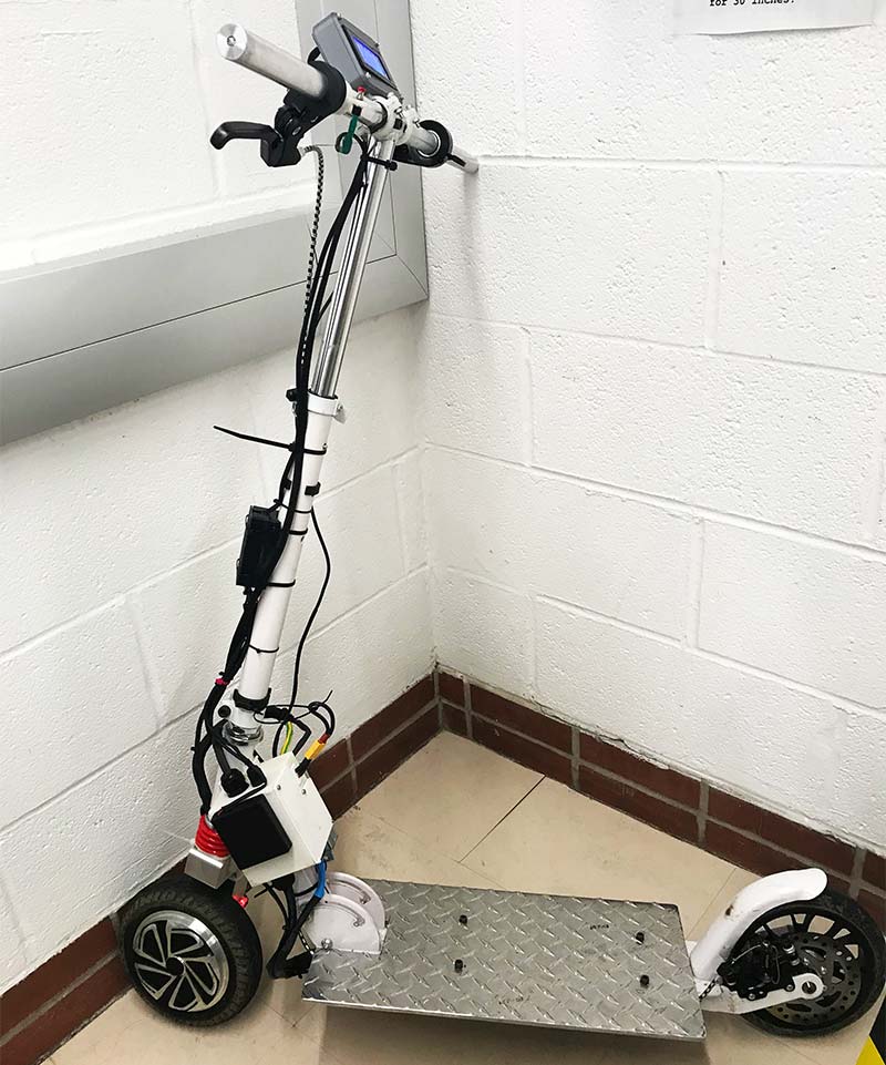
FIGURE 1. Completed scooter.
This project started early summer in 2019 when I got the idea and continued for six months when I finished up all the electronics and code. Although this was a very time-consuming project, I loved every second of the process and enjoy showing people this project. All I need now is a helmet!
The primary purpose of this article is to show my design and manufacturing process, so that you can learn from what I built. I’ve endeavored to provide as much information about my design as concisely as possible.
The Physical Design
Building an electric scooter starts with two key components: the scooter frame and motor. There are two main types of motor drives for DIY scooters: belt/gear driven, or direct drive such as a hub motor. I opted for a brushless hub motor that was designed to be used on a standard hoverboard. The main reason I chose this motor is because of its unmatched power-to-cost ratio. As hoverboards were mass produced, the cost for the motor was orders of magnitude less than I could find anywhere.
Additionally, it was relatively simple to design a mount that could hold the motor to the turning axel. I wanted the motor to be in the front to keep the hand-controlled rear disc brake working. This handbrake is extremely important for an electric scooter in an area with major hills and dangerous traffic.
The largest mechanical challenge to overcome was the design of the wheel housing. Since I opted for using a hub motor, the motor mount had to support the weight of the user in addition to the torque of the motor accelerating and turning. At purchase, the scooter had a weak wheel assembly that would not be easily modified to support the motorized wheel. Figure 2 shows the wheel assembly being cut from the hex extrusion.
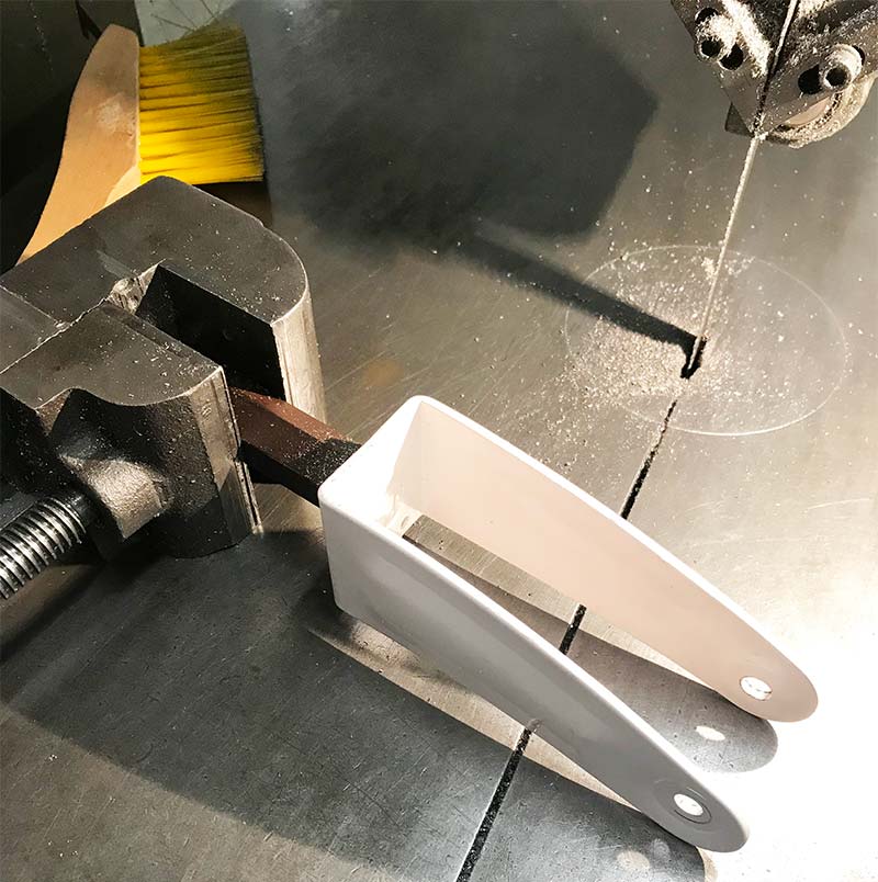
FIGURE 2. OEM wheel assembly cut with band saw.
Next, I used a large scrap piece of aluminum and designed a frame that holds the motor. It’s clamped with four machine bolts and a small stock piece with through holes. I used Autodesk Inventor to create the part (which is included in the downloads).
This design consists of two pieces: the main L-shaped piece which connects the handlebar actuation to the motor, and the other clamps the motor to the base with four 10-32 bolts. I was able to use CAM in Fusion 360 and a CNC machine to make the main part, with additional manual milling and tapping to finish up.
Finally, I used a manual mill to cut the base clamp and added through holes for the bolts. Figures 3-6 show the CAD model of the wheel assembly in addition to the assembly process of mounting the wheel. On the base of the scooter are two rails that support the weight of the rider, which I utilized to also hold the two LiPo batteries securely. Since LiPo batteries are highly unstable and susceptible to both water damage and puncturing, I added a metal cover to protect the batteries from each of these factors.
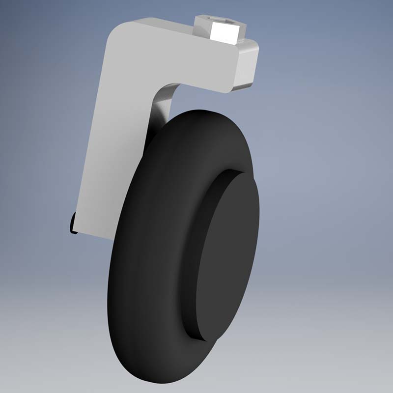
FIGURE 3. CAD of CNC wheel assembly.
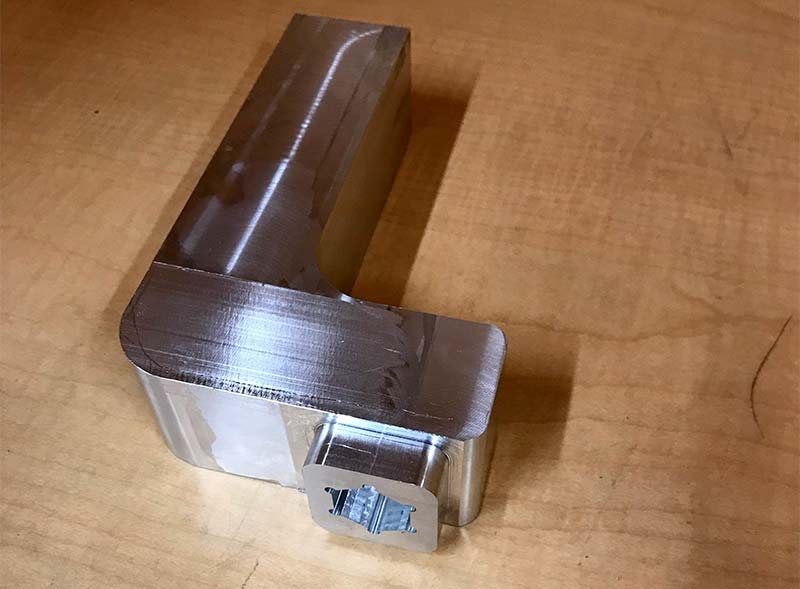
FIGURE 4. Completed CNC wheel assembly with attached hex.
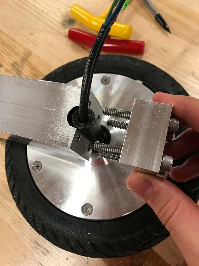
FIGURE 5. Close-up of motor mounting.
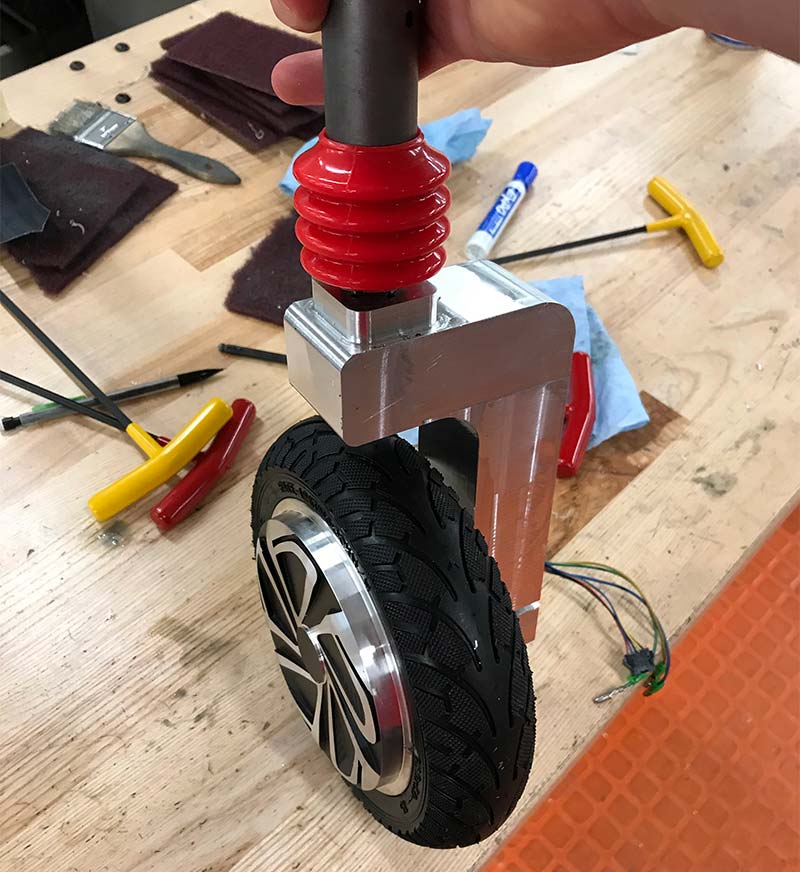
FIGURE 6. Final front wheel assembly.
To do this, I cut a piece of 1/16 inch aluminum and bent these pieces to length using a metal bender and acetylene torch to reduce the stress on the metal while bending. With normal use, the bottom is likely to be scuffed (refer to Figure 7), but the metal cover takes all the damage with no issues so far.
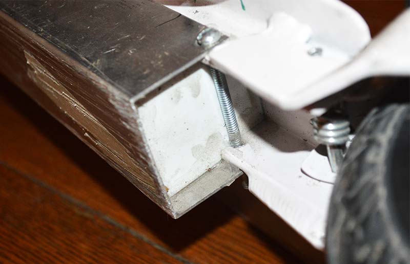
FIGURE 7. Close-up of the metal frame protecting the batteries.
I used 3D printing extensively in both the prototype stage as well as in the final product. The most obvious piece is the electrical box which is how the user can charge the LiPo batteries easily. This box has the main power switch, voltage divider for the Arduino to read battery voltage (as max analog in is 5V and the controller runs off 12V LiPo), and the LiPo charging connectors.
To charge this scooter, the user takes the front panel off (held down by M3 screws), detaches the XT-60 connectors from the main power, and simply plugs them into the LiPo charger. Additionally, the LCD screen housing, Arduino Nano case, folding mechanism, and waterproofing pieces are all designed and 3D printed for this scooter. All the CAD files are provided in the downloads for use in your own scooter.
Figure 8 highlights the electrical box and controller connected to the scooter frame. To attach the controller, I drilled and tapped two holes into the frame and bolted the controller on with two 10-32 bolts. The elctrical box was connected using a single bolt and a zip tie.
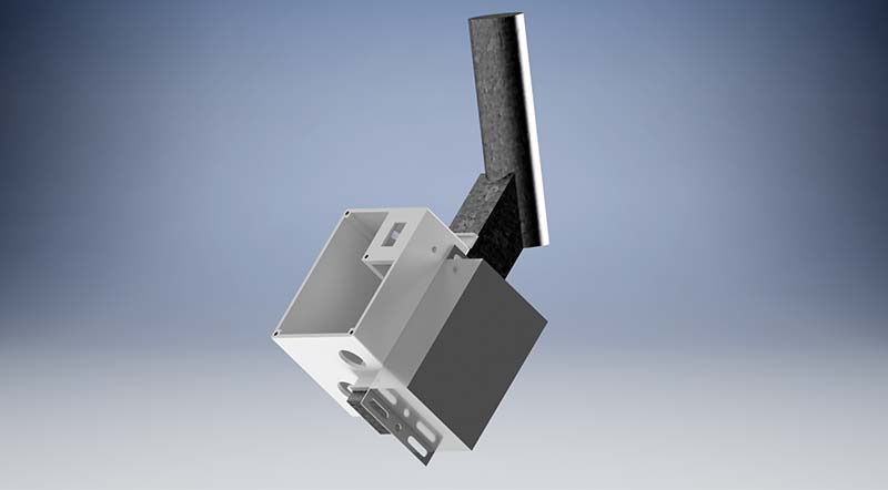
FIGURE 8. CAD of the scooter frame with the controller and electrical box.
This method of attaching works very well, with both boxes secured soundly. I didn’t want to reduce the strength of the scooter too much which is why I opted for as few holes into the scooter as possible.
Later in the build, I noticed that riding the scooter could be very awkward since both of my feet couldn’t fit comfortably on the small platform. This is likely because the engineers designed the scooter for the user to have one foot on the frame and one to push the scooter forward. To remedy this, I knew I had two options: add a metal plate to the top, or cut off the main frame and weld on a new one.
Sadly, I didn’t have access to a welding machine and thus had to use the first option. I was able to find a quarter inch aluminum plate that was large enough to cover the platform. I utilized a bandsaw and grinder to cut the plate to length in addition to adding a slot for the folding mechanism as seen in Figure 9.
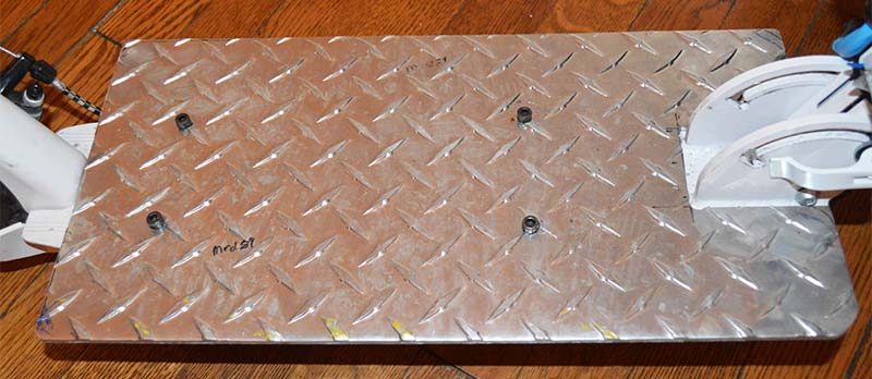
FIGURE 9. Scooter with added standing platform.
The final major modification of this scooter was the handlebars. The handlebars that came with the scooter were so close together that it was very unstable and difficult to steer — especially at a high speed. To remedy this, I purchased an aluminum stock at one inch diameter and used a lathe to reduce the diameter until it fit into the frame.
Finally, I drilled and tapped two holes for 10-32 machine screws to hold the new bar onto the original frame. With the longer handlebars, the scooter was much more comfortable to ride and felt more stable around turns.
One key theme I had throughout all my designed components was to keep the whole system waterproof. Although it would not be wise to ride this in heavy rain, all the main electronics should be watertight. The primary concern for water is the batteries which are below the scooter.
To enclose the batteries as mentioned earlier, I bent an aluminum sheet to protect the undercarriage but also 3D printed pieces with slots for cable gland joints wire protectors to allow the wires to pass through. There are three different slots for the cabling to pass through as shown in Figure 10: main power; LiPo battery management; and battery temperature sensors. These slots were fitted with nylon cable gland joints that are watertight and very simple to use.
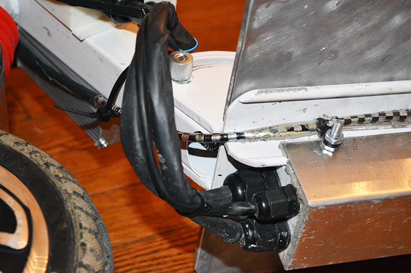
FIGURE 10. Photo of completed undercarriage of scooter.
Finally, I used Dynaflex 230 to completely waterproof the batteries which can be seen around the edges in Figure 10. These wires then pass to the main electrical box which uses the same cable gland joints as in the electrical box and are sealed using heat shrink tubing. Finally, each wired connection has more silicon at each joint to ensure there are no leaks.
Electrical Components
Once I picked the hoverboard wheel as my motor of choice, I decided on the controller in Figure 11 because it worked with my brushless motor and was very inexpensive. The batteries were a little more difficult to pick out.
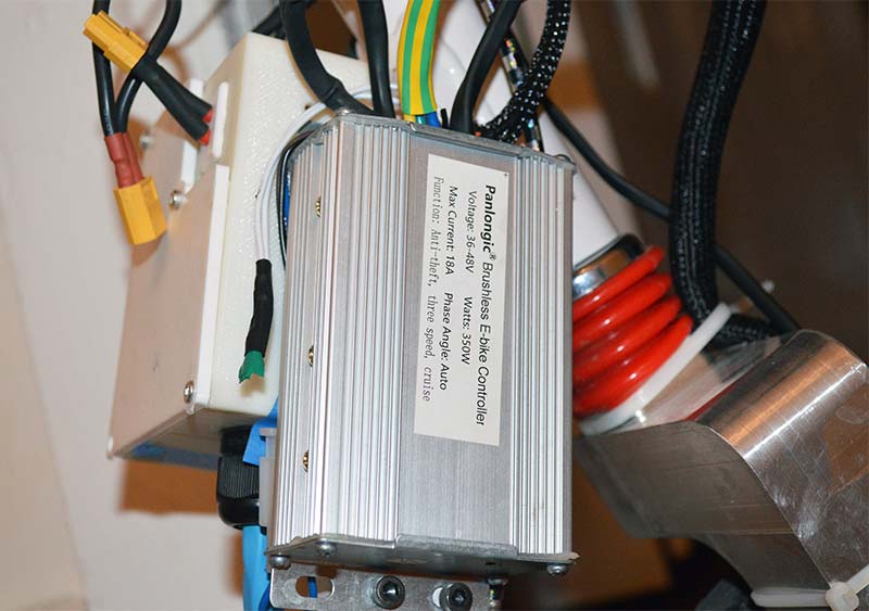
FIGURE 11. Close-up of controller mounted to the scooter.
Since almost all scooters and bikes use Li-ion battery packs, I thought they would be the best option for me. The reason they are so widely used is due to their excellent storage capacity, charging characteristics, and they can be designed to fit almost any form factor.
Although I did do significant research into the design of a pack for my scooter, I realized I didn’t have the funds to purchase a spot welder which is used in the building of these packs. In the future, I would be interested in making another scooter or similar project where I use 18650 batteries instead of standard LiPo batteries used in this build.
To find the allowable dimensions for my batteries, I took a bunch of measurements with calipers and made a very rudimentary model using Autodesk Inventor as seen in Figure 12. With these dimensions in hand, I was able to choose the batteries to fit under the main frame of the scooter.
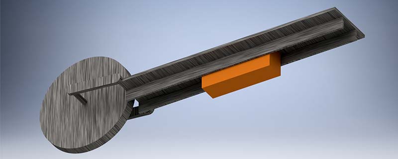
FIGURE 12. Simple CAD of scooter with battery (in orange).
I had 43 mm to work with for the width of the batteries, with slightly more room to allow the batteries to fit under without hitting the ground. The batteries selected were 6S and had 4,000 mAh battery life, which is a little lower than I had hoped for.
Overall, the main electrical circuitry for this scooter was quite simple to design. As shown in Figure 13, I have the two LiPo batteries connected in series which power the controller and motor. The controller reads the thumb throttle potentiometer mounted on the handlebar to set the speed of the motor. Additionally, I added a cruise control button also mounted to the handlebar next to the break. The motor is controlled with three-phase power with three Hall sensors which all output to the controller.
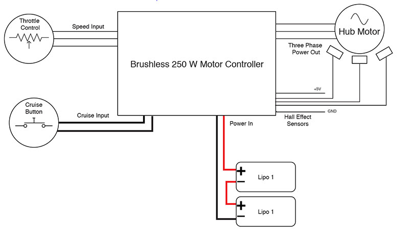
FIGURE 13. Scooter power driver circuit diagram.
Now that I had the main design of the scooter, it seemed extremely easy to wire up and ride. That, sadly, was not the case. Wiring up the batteries and temperature sensors was surprisingly difficult to fit them into my allotted space.
At this point in the build process, I had finalized the design of the undercarriage and the electrical box which was mounted as you can see in the final design back in Figure 1. I began by placing my temperature sensors with excess cabling through the gland joints in the base, in addition to the LiPo charging cables (26 cables in total).
Finally, I took my two XT-60 connectors and ran the cabling up to the control box. This wiring procedure can be seen in Figure 14 which shows the initial cable routing into the battery section.
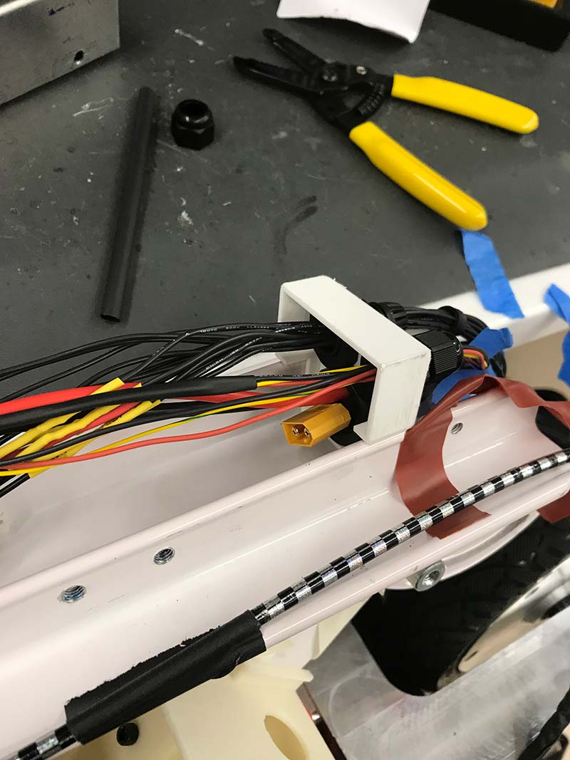
FIGURE 14. Wiring the batteries into the frame base.
I then placed the LiPo batteries into the frame which fit in snugly, and began connecting the different plugs. After having significant trouble fitting the batteries and connectors into the allotted room, I realized I had to change something to get everything to fit without putting significant pressure on the cables.
I noticed that the XT-60 connectors took up a large amount of space, so I decided to remove them and have straight soldered connections. I wouldn’t recommend removing the connectors, but it was easier to remove them than it would have been to redesign the housing.
I removed each of the connectors one cable at a time, being extremely careful not to have anything short. I used extensive heat shrink tubing and electrical tape to ensure they were well insulated. As seen in Figure 15, all the wiring on the base was done and taped in place for the heat shrink tubing.
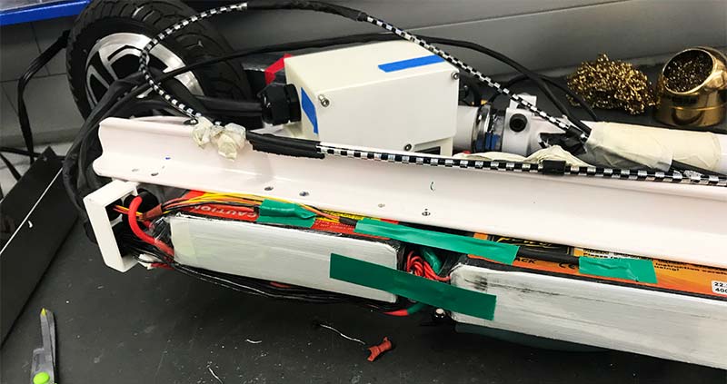
FIGURE 15. Final battery pack before shrink wrap.
I then placed the taped-up system into the heat shrink tube and slowly shrunk the whole system down until it looked like Figure 16. After this, I placed the metal sheet on for a final time and tightened down all of the bolts with Loctite to make them permanent.
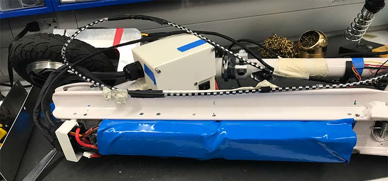
FIGURE 16. Heat shrink battery packs.
As discussed briefly earlier, I designed an electrical box which sits next to the motor controller. The schematic for this simple box is shown in Figure 17.
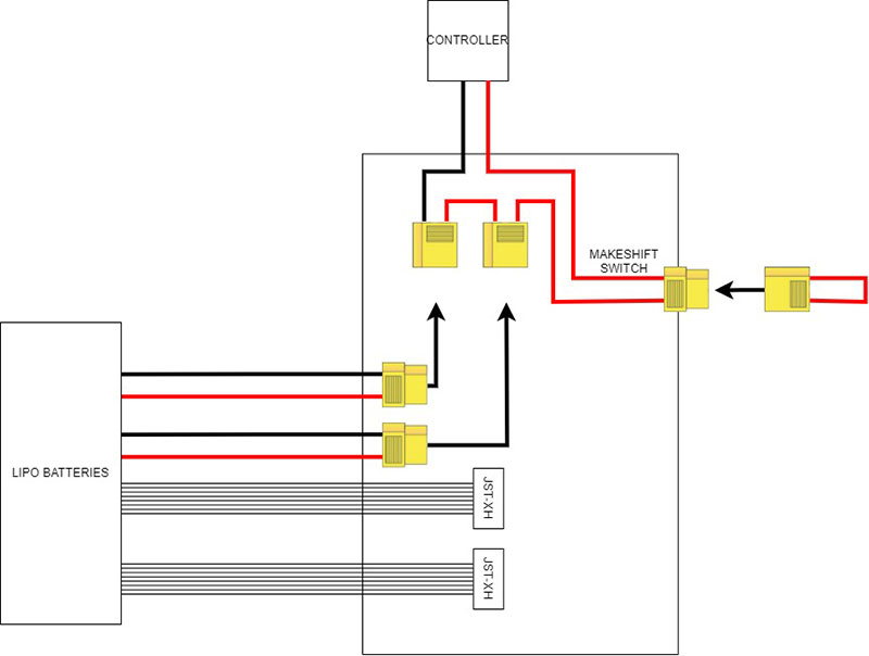
FIGURE 17. Electrical box schematic.
To charge each of the batteries, I simply remove the male connectors from the control box and plug them into a balancing charger along with their respective balancing cables. As mentioned earlier, I would have liked to use a Li-ion battery pack which would have made the charging process much simpler and seamless. As I only had a single charger, I had to charge each battery separately.
When using the scooter, I plug in the battery’s connectors into the female connectors which put the batteries in series. In my first design, I had a standard rocker switch which was rated for 10A at 125V AC which was significantly lower than my power usage (around 250W vs. the 125W rating). These switches are really only meant to switch AC current which is much easier to do.
Sadly, within a few days of use, the switch had completely burnt out. After much research, I found any DC switch would be much too large to fit inside or near the control box. Instead, I opted for a makeshift switch with a shorted female XT-60 connector which was used to short or open the circuit. Although it’s certainly not the cleanest switch option, it’s very functional and has presented no issues so far.
From there, I wired up the controller to the electrical box and motor leaving plenty of slack for the wheel to turn. At this point, the scooter movement was complete. It was now time to design the LCD screen and accompanying sensors. The functionality I was looking for from my LCD screen was to show the battery voltage, approximate percent of battery life remaining, speed, and miles driven. The most difficult of these was getting the speed measurement working well.
To do this, I thought of piggybacking on the Hall sensors the controller uses, but I was worried that might interfere with the main control. Instead, I decided to use a Hall-effect sensor reading when a neodymium magnet connected to the wheel passed by the sensor. One issue with this design is how close the open electronics were to the wheel which would splash up water.
I designed a simple mold in which I placed the electronics and an epoxy called Dragon Skin 20 as seen in Figure 18.
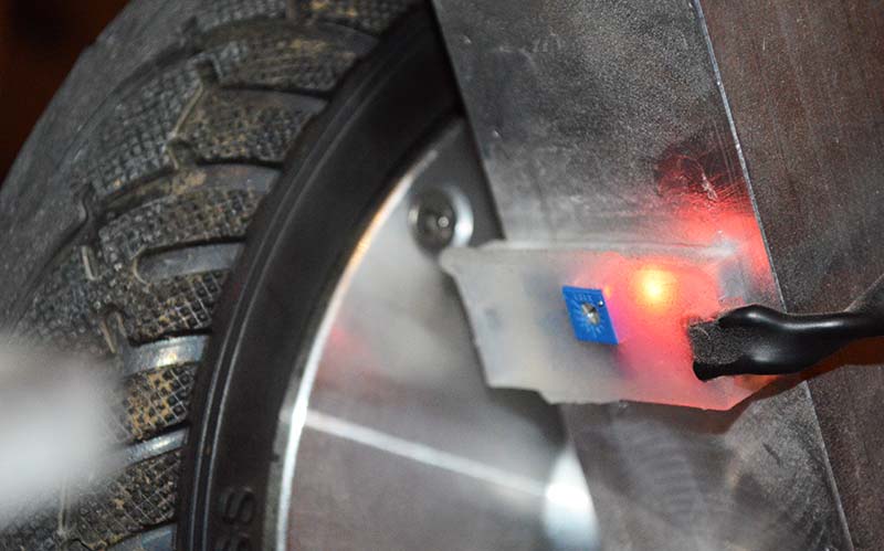
FIGURE 18. Waterproofed Hall-effect sensor.
I left the epoxy off the module in blue which allows me to tune the sensitivity of the sensor. Figure 19 shows the screen housing built to hold the 20x4 character LCD screen and connect to the handlebars via screws.
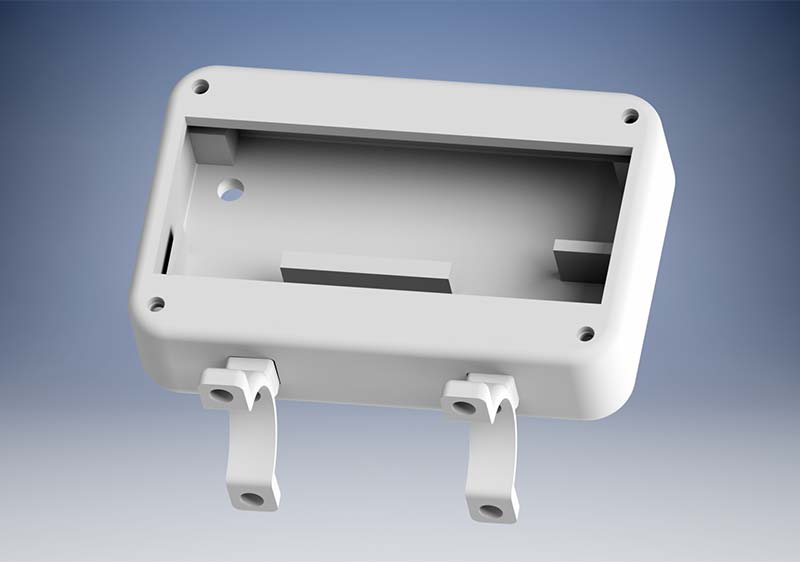
FIGURE 19. CAD model of LCD screen housing.
Additionally, I built a simple box to hold the Arduino Nano and associated wiring (Figure 20). Both the housing box and screen housing utilized M3 standard hardware, including heat inserts which are melted into the parts using a soldering iron.
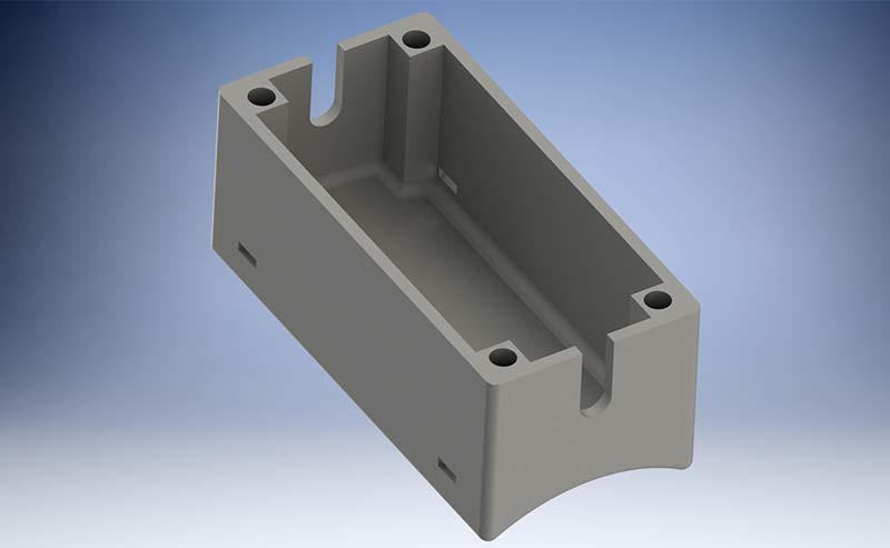
FIGURE 20. CAD of small electrical box for Arduino Nano.
Finally, I soldered all the headers onto the Nano and placed the microcontroller on a small protoboard. I then added female headers around the Arduino with six power and six ground connections on the side. Figure 21 shows a prototype box being wired up to test.
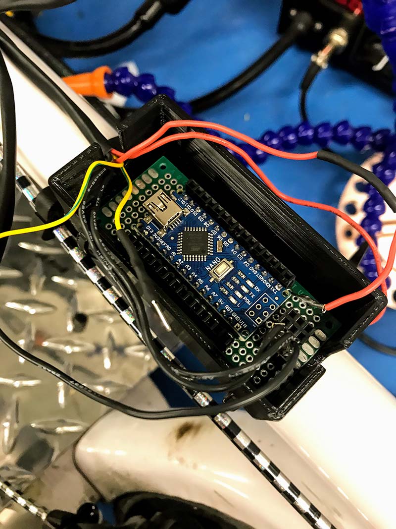
FIGURE 21. Prototype of the Arduino Nano box.
I used crimped connections to attach each device to the protoboard, just in case there are any wiring issues in the future. To measure the battery voltage, I added a voltage divider to the electrical box with 47K Ω and 4.7K Ω resistors in series with the Arduino connected to the 4.7K Ω resistor. The purpose of the divider is due to an Arduino running off 5V and thus being able to measure a maximum of 5V. The circuit divides the voltage of the battery by almost exactly 10, making it readable to the Arduino. The Nano schematic is shown in Figure 22.
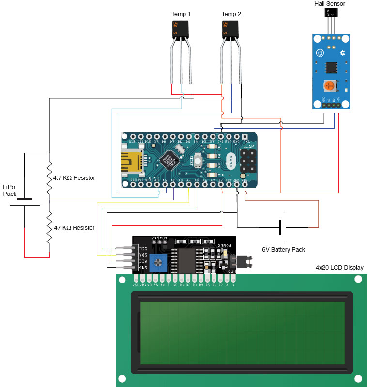
FIGURE 22. Overall Arduino, sensors, and LCD screen schematic.
Programming
The code for the Arduino is included in the downloads. I’ll go ahead and explain the methods I used in programming this system. The hardest part of this program was getting the Hall sensor odometer and speedometer working correctly with a limited clock speed. To read the Hall sensor, I connected the output to the second digital pin which is capable of running hardware interrupts.
At every rising edge of the Hall sensor signal, the interrupt is triggered and runs a simple function seen in Figure 23.
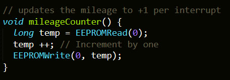
FIGURE 23. Hardware interrupt incrementing function.
This function increments the counter which is stored on electrically erasable programmable read-only memory (EEPROM). EEPROM is a non-volatile memory which means it’s stable when the device is not powered. Accessing this memory is not as simple as defining a variable to memory; you need to send a byte of data to a specific memory address. Sadly, as the Arduino runs off an eight-bit architecture, the system would not be able to store the odometer reading in a single memory address. To fix this issue, I built some basic helper functions that write and read a “long” variable to four eight-bit memory addresses as shown in Figure 24.
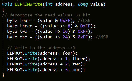
FIGURE 24. Helper function to write to EEPROM.
To read the value from memory, I used a bit shift operator after reading the four bytes from memory as seen in Figure 25.

FIGURE 25. Method to bitwise convert 4x eight-bit int into a “long” variable.
The speedometer part of this program is run off TimerOne, which is a 16-bit timer running at a frequency of 16 MHz. I set the period of the timer to trigger an event every quarter second to read the odometer, compare it to the previous reading, and then calculate the speed.
The program calculates the speed by converting the change in rotations to distance. I made an array of four of the most recent speeds and output an average to smooth out the data for the LCD screen.
The temperature sensors were very easy to set up using the datasheet and a basic analogread as shown in Figure 26.

FIGURE 26. Reading of battery temperatures.
Additionally, I read the battery voltage with a very similar method, but I multiply by 10 due to the voltage divider circuit. Refer to Figure 27.

FIGURE 27. LiPo voltage reading.
The final setup was putting it all together in one program and integrating it with the LCD.
Using this LCD screen is extremely easy with the included libraries. I had to do a few tests on the LCD to ensure the placement of the mileage, speed, temperature, and voltage would not overlap and look nice as shown in Figure 28.
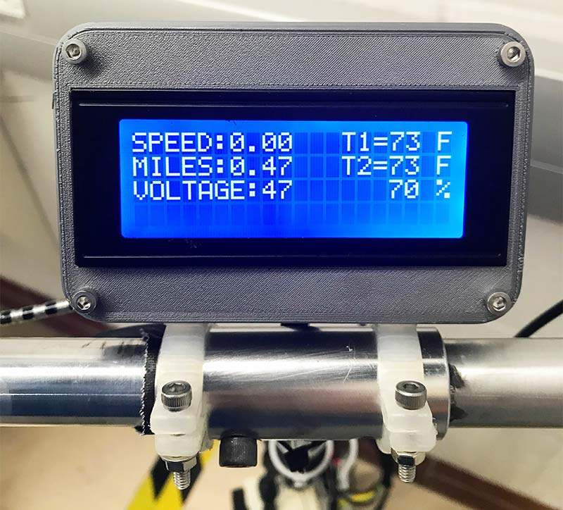
FIGURE 28. Working LCD screen.
Conclusion
Overall, this project was very educational. It was exciting to design the entire unit, from mechanical components to the hardware and software used. The final product has a surprising amount of power; it’s able to move me with a backpack up any hill that Ithaca, NY has to offer. I was pleased and impressed by the power the hub motor output.
Additionally, the LCD screen is very responsive and accurate with the speed and odometer measurements. Although I haven’t been able to test the range on a flat road, I estimate it’s around 6-8 miles on a single charge based on previous rides. This is lower than many scooters on the market, but I was working with very limited space under the scooter and LiPo batteries.
I would recommend building something like this to anyone who can commit the time. I logged most of the time I spent working on this, and the total was around 100 hours!
In a perfect world, I would have welded a new frame to the existing scooter. This would have given me additional room to stand comfortably and fit all of the electronics in a larger space.
In the future, I’d like to experiment a bit with building a Li-ion pack to power the scooter. I loved working on this project and learned so much. I hope I inspired some of you to build your own! NV
Parts List
I purchased the parts from a variety of places.
Amazon:
Generic Parts from a Chinese Warehouse:
- Hall Sensor
- Arduino Nano
- 12 gauge Wiring
eBay:
- Potentiometer Thumb Throttle
- Eight inch Brushless Hub Motor for Hoverboard
From the Community Maker Space at Cornell:
- All Other Parts
- Temperature Sensor
- Wiring
- Soldering
- 3D Printing Supplies
Downloads
What’s in the zip?
Code and CAD Files