In years past, non-polarized capacitors would often have a striped end on the capacitor tube, or a stripe marking on the capacitor body indexing with one of the leads. While not a polarized capacitor in the electron flow sense, these capacitors did indeed have a “polarity” which would often need to be observed for best performance. The purpose of the stripe is evident if we look at some of the old “waxies” that were actually marked “Outside Foil End” on one end of the capacitor tube (see Figure 1).
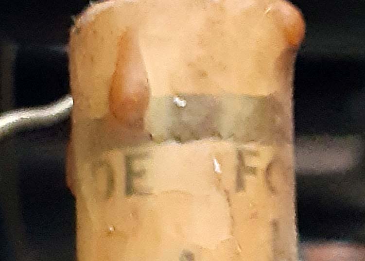
Figure 1 – Outside foil end marking #1.
Yes. You read that right. The stripe on the capacitor body indicated which device lead was connected to the outside foil within the capacitor. So, why did that matter? And does it still matter today? Read on, MacDuff!
The importance of knowing which lead is connected to the outside foil begins to become apparent when we look at just how the capacitor is connected in-circuit (see Figure 2).
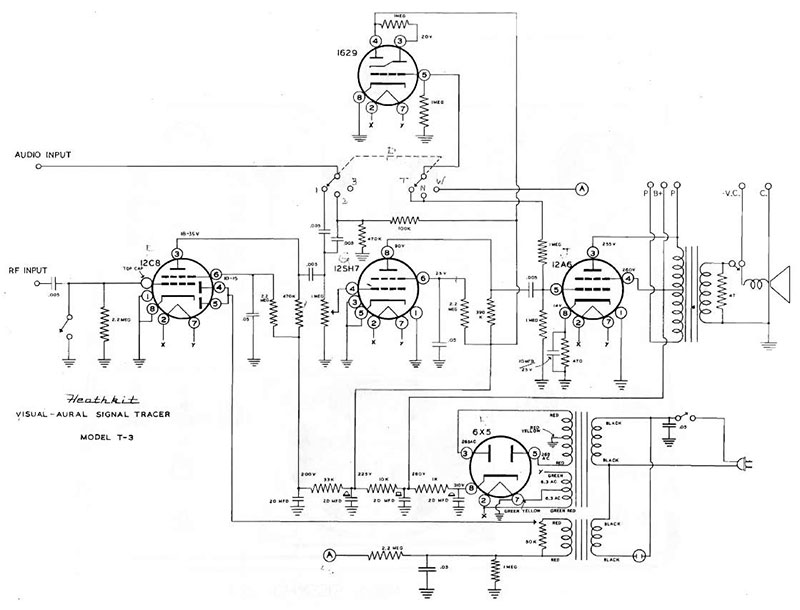
Figure 2 – Heathkit T-3 schematic diagram.
When properly installed, the capacitor will be oriented in such a manner that the outside foil lead is connected to the lowest impedance (usually the ground) side of the circuit. As the Figure 2 schematic shows, the vast majority of capacitors have one lead tied directly to chassis ground.
The capacitor can and will behave as an antenna, “receiving” RF signals that are present in the vicinity. Having the outside foil grounded tends to shunt off any such received signals to ground rather than allowing them to enter the working circuit in the form of unwanted and interfering noise.
Unfortunately, many modern capacitors are no longer marked, and very often when a capacitor does have a stripe, it’s not related to the outside foil marking and must therefore not be used as a connection guide. Instead, it’s up to the builder to determine which lead is the outside foil lead and to assemble the circuit in accordance with that determination.
A recent discussion with an engineer at Cornell Dubilier regarding their Illinois Capacitor MWR series of metallized polyester film capacitors confirmed that the MWR capacitors are not marked as to the outside foil lead, regardless of what markings may be on the body of the capacitor. Now, I already suspected that, which is why I called him to begin with.
What I mostly wanted from him was his recommendation as to test frequencies, voltages, and loads. See, I had developed my own methodology for identifying the outside foil lead (which is the real purpose of this article) and I was seeking validation for my method.
It used to be that I could easily determine the outside foil lead of a capacitor simply by connecting the capacitor to an oscilloscope and watching the display as I held the cap in my fingers. I’d use a piece of coax with a BNC connector at one end to fit the ‘scope input jack and a pair of alligator clips — one red (center conductor) and one black (shield braid) for easy differentiation – on the other end (see Figure 3).
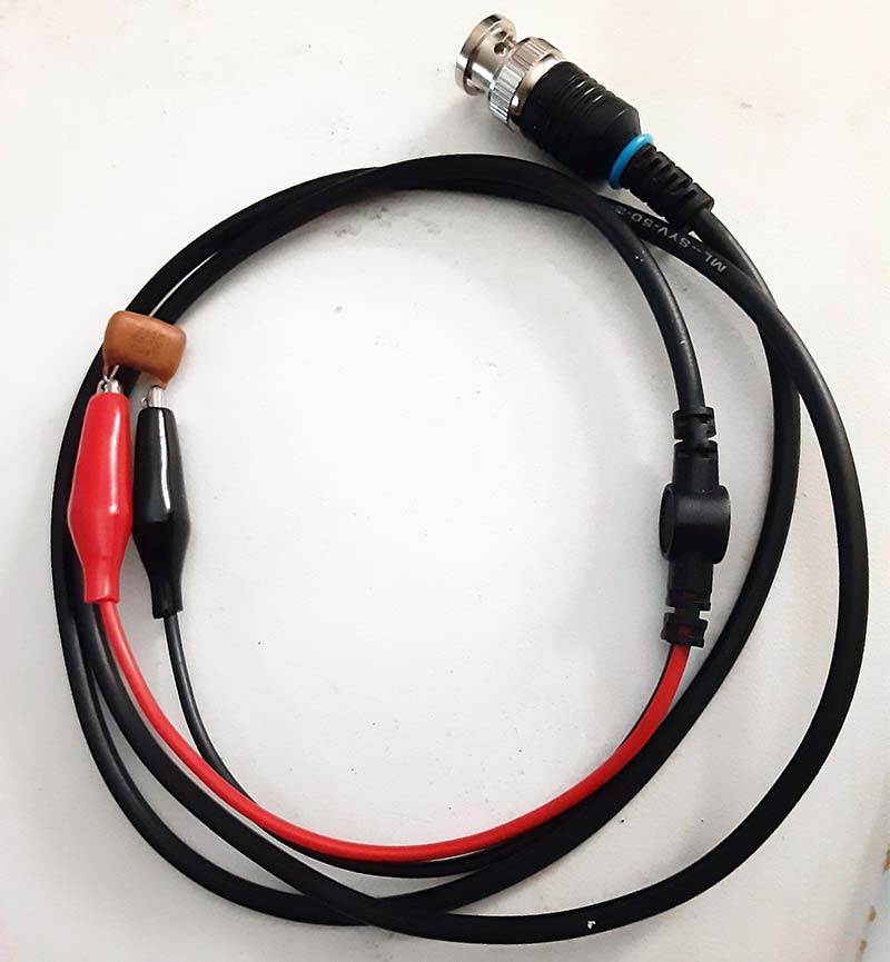
Figure 3 – Alligator clips on coaxial cable.
Set the ‘scope to a low voltage setting; about 2 mV or 5 mV per division should be fine. Set your time base to a fast speed. You can adjust it later to get a clearly defined and visible trace. Now, connect the capacitor between the two alligator clips, and holding the capacitor between your thumb and forefinger, look at the trace on the ‘scope. Adjust the time base as necessary to get a clean trace, and then note the amplitude of the waveform displayed (Figure 4).
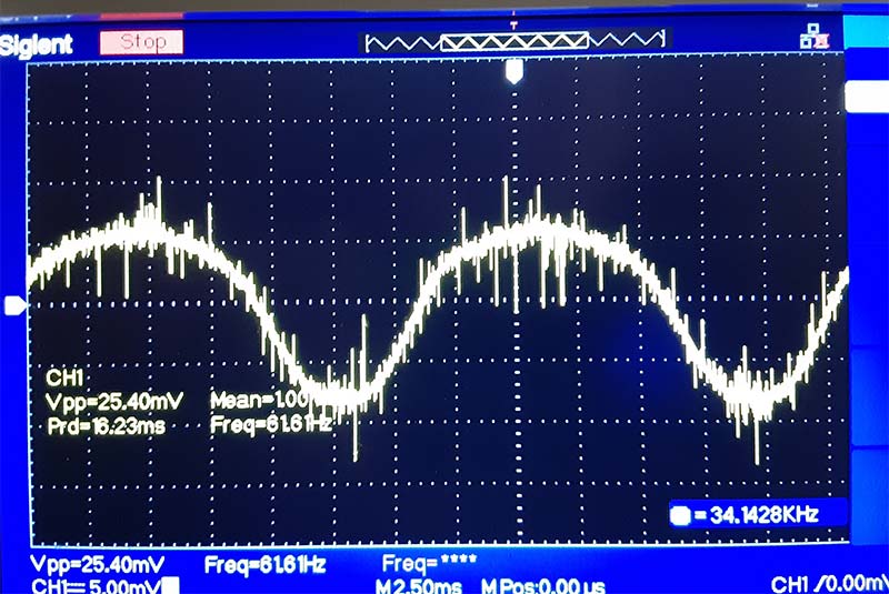
Figure 4 – Greater amplitude signal trace.
Your body is serving as a big hum antenna, feeding the hum signal through your fingers, and then inductively coupling it into the capacitor where the ‘scope can measure it. After noting the trace amplitude, reverse the relative position of the capacitor in the alligator clips and once again look at the trace. One of these two waveforms will be of a lesser amplitude than the other, and this is the one that interests us (Figure 5).
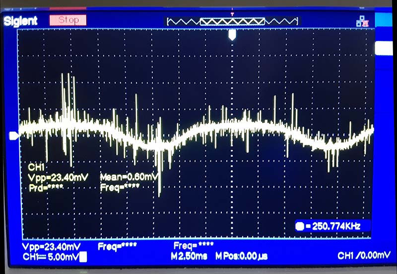
Figure 5 – Lesser amplitude signal trace.
When you have determined which waveform has the lower amplitude, carefully note which ‘scope lead is connected to which capacitor lead. The way this works is actually quite simple. The capacitor lead that is connected to the ‘scope common or coax shield braid (black alligator clip) side when the trace amplitude is at its lowest is the capacitor lead connected to the outer foil. I generally score these leads with a Sharpie® marker once I track them down.
So far, this is pretty simple and straightforward, right? Not so quick, Rick! Some of the newest capacitors on the market (such as the MWR series mentioned earlier) are produced using a so-called “non-inductive wrapping” technique or process. What this means is that the test method described above — which relies on inductive coupling of the hum signal into the capacitor — will not work with these capacitors.
As a result, I had to find another way to identify the shielding lead of the capacitor because, yes, it does still matter — especially when refurbishing older equipment that relied on capacitor shielding to limit noise or hum in the system. One such device is the Heathkit T-3 Aural/Visual Signal Tracer that I’m currently refurbishing.
In sum total, the T-3 uses the following capacitor types and quantities:
- 0.005 µF 600V – five pieces
- 0.02 µF 600V – one piece
- 0.05 µF 600V – four pieces
- 10 µF 25V – one piece
- 20 µF/20 µF/20 µF/20 µF 450V – one piece
Let’s look a little bit closer at this, starting at the bottom of the list. That last capacitor on the list is a four-section can-type electrolytic filter capacitor used in the T-3’s power supply. Many years ago, I had the need to replace this capacitor, and at the time I could only find a 20-20-10-10 can as the closest replacement (Figure 6).
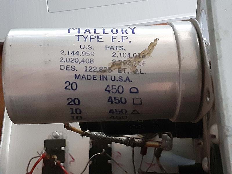
Figure 6 – Existing multi-section electrolytic “can” capacitor.
I wanted to remain with the can-style filter rather than installing four discrete devices, so I went ahead and installed it. However, it always bothered me because its use did result in some hum in the audio. The hum was very slight, but I knew that it was there and it just irked me.
Thirty-some years down the road, I’m able to get an almost exact 20/20/20/20 capacitor. I say almost because this replacement is rated at a slightly higher 475 volts than the original 450 volts.
Next is the only other polarized capacitor in the T-3. It’s a 10 µF 25V axial aluminum electrolytic type (Figure 7) and was an easy find for replacement, so is being replaced with an exact match.
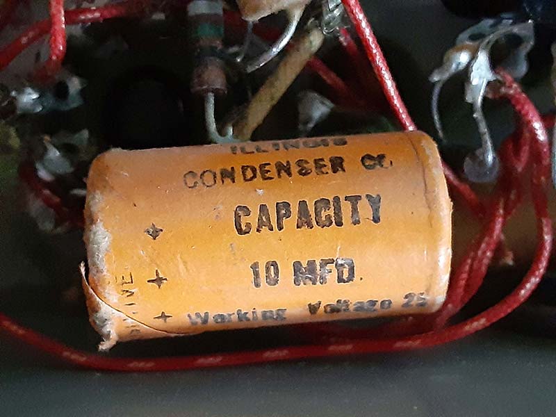
Figure 7 – Original axial electrolytic capacitor.
Let’s move on to the three remaining values. The originals were all wax and paper capacitors (Figure 8) which are well-known for becoming leaky as they age, thus passing DC instead of blocking it.
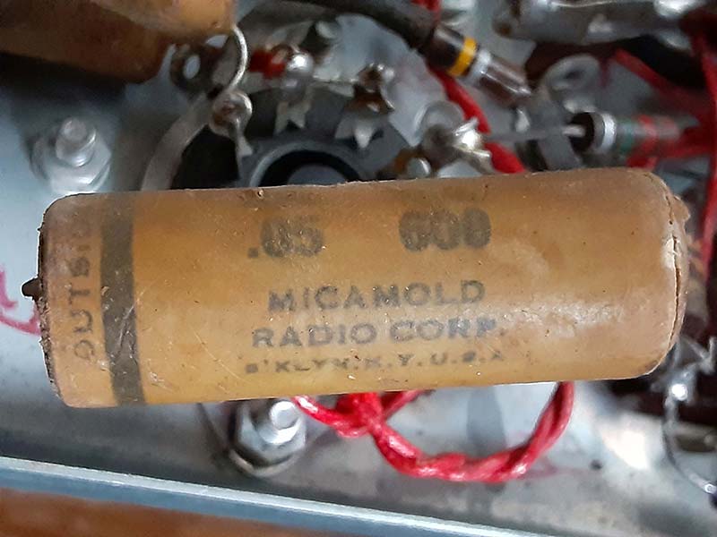
Figure 8 – Original “waxie” capacitor.
These capacitors act more like resistors than capacitors when they get some age on them.
The original waxies are all of values that are not so common today. The 600 volt rating is also no longer a common value. After some thought and research, I settled on metallized polyester film capacitors rated at 630 volts. I chose 0.0047 µF to replace the 0.005 µF waxies, 0.047 µF in place of the 0.05 µF ones, and 0.022 µF in place of the lone 0.02 µF capacitor used.
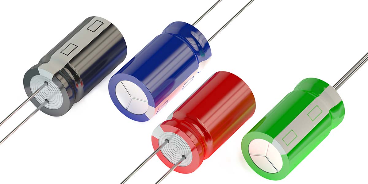
Installation of the can capacitor is simple enough. The can is marked with shaped icons at each of the four section terminals; actually, at three of the four. This is a standard means of identifying which terminal goes to which section as to the values of those sections.
In this case, because all the sections are of the same value, it’s really moot. However, the capacitor is still marked with the usual square, triangle, and “D” or closed “U.”
As is the norm, the legend is on a label on the side of the capacitor, and each of the terminals is labeled on the end insulator right next to the terminal. The terminal end of the can has four mounting tabs by which it’s secured into its mounting wafer, which is itself secured to the chassis by machine screw and hex nut combinations. Each of the tabs are engaged into a slot in the wafer and are then either twisted or folded over to secure the capacitor to the wafer. It’s also generally advisable to solder at least one of the tabs to ensure a good ground for the capacitor shell.
The axial electrolytic capacitor is clearly marked as to its negative end, so installation of this one is also quite simple. It’s placed parallel to a 470Ω resistor between the cathode (pin 8) of the 12A6 audio output vacuum tube and ground. As such, the negative-marked end of this capacitor is connected to the unit chassis, which is done at the ground eyelet of the 12A6 tube socket.
It must be noted that the original Illinois Condenser electrolytic capacitor that’s installed has its positive end marked, and the pictorial that is provided in the T-3 manual shows a striped end on that capacitor — but the stripe is at the positive end.
So, now we come to the troublemakers: the film capacitors. Not knowing at the time about the manufacturing process that produces “non-inductive wrapping,” I attempted to determine the outside foil end using the old standby oscilloscope method described previously. Needless to say, it didn’t work.
Thinking over that process, though, I decided that for some reason the inductive coupling was not happening. That being the case, I figured that I could pass a signal through the capacitor from my signal generator and use the ‘scope in the same manner.
Unfortunately, that didn’t work right out of the box either. I was using a 5V sine wave at 10 kHz, which simply showed a basically clean sine wave through the capacitor in both directions.
So, I added a series resistance of 100KΩ and ran the test again. This time, I got useful results in that when connected in one direction, the trace was a clean waveform, but in the other direction the waveform was very noisy.
Figure 9 shows a diagrammatic representation of the test setup, while Figure 10 depicts the test setup in use.
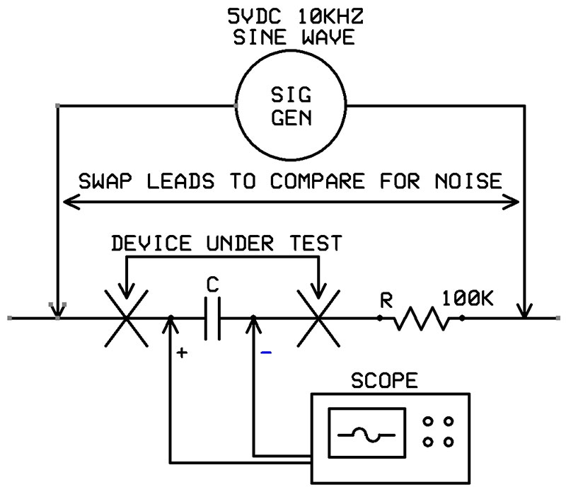
Figure 9 – Test circuit for non-inductive capacitors.
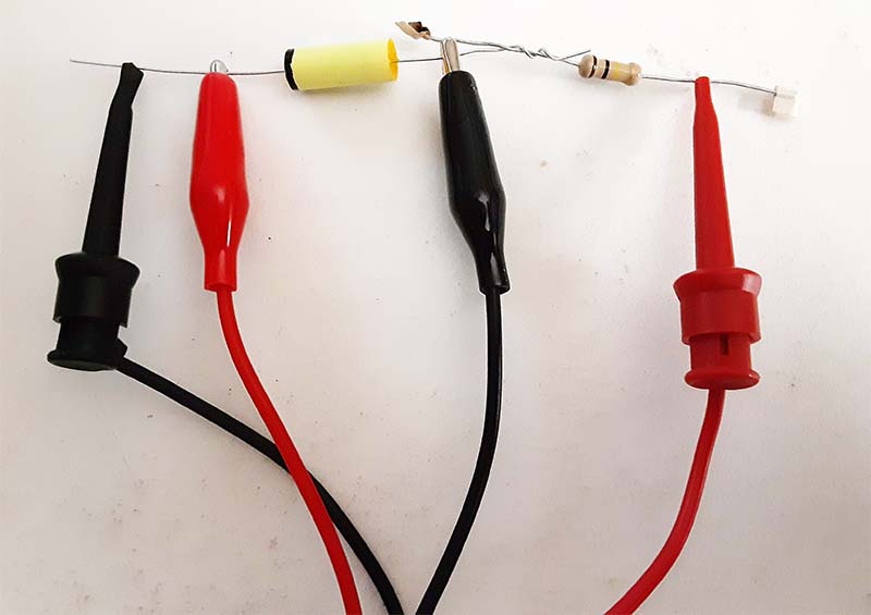
Figure 10 – Testing arrangement for non-inductive capacitors.
Eureka! I was on to something, so I decided to seek out some validation.
I made a call to CDE and spoke with an engineer who started off by stating that there is no way to tell which is the outside foil end by looking at the capacitors, and that the information printed on the capacitor bodies was printed in the opposite direction with every other capacitor off the line.
The printing reversed with each capacitor that went by, so it was impossible to determine the outside foil on one capacitor and then assume that all its “twins” in a given lot were the same. In reality, the odds were that any given batch would have half of each printing direction.
He went on to describe a test circuit that was essentially the same as what I had developed and used, which would produce a clean waveform in one direction and a noisy one in the opposite direction. He said that any voltage up to the working voltage was acceptable, so long as the current was limited to a level that the capacitor could handle in accordance with the datasheet values.
He recommended a frequency of anywhere from 5 kHz up to 15 kHz, and he said that the polarity of the least noisy waveform would indicate the polarity of the capacitor.
Of course, there is no “outside foil” on these capacitors. Instead, the polarity would indicate which end is the shielded end. I had my validation just like that! Almost as an afterthought, he did say that capacitors with the shield end marked are available from CDE as special-order items, with certain specific minimum order piece counts applied.
Armed with the knowledge that my test method was valid and reliable, I went through the bags of polyfilm capacitors that I had bought for the T-3 refurb and identified the shielded end of each one, marking that end of each capacitor with my trusty Sharpie.
Figures 11 and 12 show the results of this testing method, with Figure 11 showing the noisy trace and Figure 12 its clean counterpart.
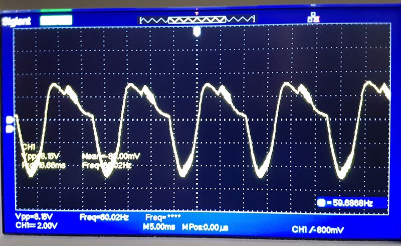
Figure 11 – Noisy signal trace.
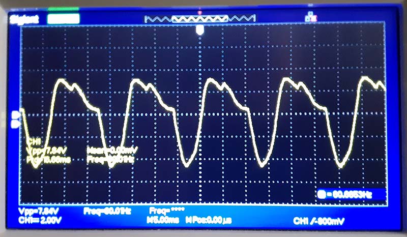
Figure 12 – Clean signal trace.
In Figure 13, it’s obvious how I marked the capacitors after testing each one.
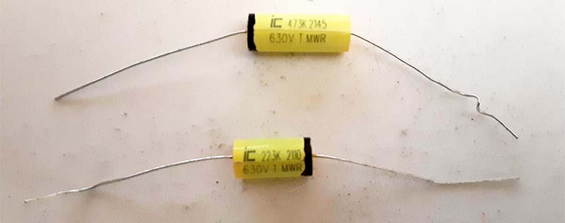
Figure 13 – Marked polyfilm capacitors.
All that remains now is to actually install them, together with a polarized line cord and a full set of replacement resistors for all the value-wandering aged carbon composition resistors that are currently in place in the T-3. NV
Why Bother?
Many folks in electronics — hobbyists and technicians alike — have quite possibly never given a second thought to the installation orientation of a “non-polarized” capacitor. So, why is this a “thing” now?
In reality, it has long been of considerable importance and, in fact, engineers have long relied on the shielding effect of such capacitors to help reduce inherent hum or buzz in the audio circuits of a wide variety of electronic equipment. What has brought it to the forefront recently is the current trend of reconditioning or refurbishing vintage electronic equipment — especially vacuum tube equipment.
As we open up some of this older equipment and begin replacing the original wax and paper capacitors — which are well past their “best by” date — we can find ourselves with audio equipment with annoying hum that we can’t seem to get rid of easily. However, it may be (and often is) just as simple as reversing the orientation of the replacement capacitors so as to connect their outer foil or shielded end to the lower impedance point in its circuit.
Wouldn’t it be a lot easier if we knew which way to install the capacitors in the first place?