This is a story of a nostalgic, useless, but fun project that spiralled out of control; a lesson in the lost black art of machine code from the bygone era of code written and debugged on square ruled paper, from an era of hand-drawn schematics and actual manual tape-out of chips.
A project that was obsolete long before it began.
I’ve written this so that those younger than me may learn a bit of history, maybe pick up a trick or two, and maybe amuse some of my contemporaries with a project for a rainy weekend or two.
What we have here is COSMAC VIP emulator that runs on a single-chip PIC18F4550 MCU with minimal hardware.
History of the COSMAC VIP
The original COSMAC VIP featured 64x32 pixel black and white graphics that were displayed on your home TV set, 2 kB of RAM memory, and an audio C-cassette storage for code you input via the 16-key hex keypad. Plus, it had rudimentary BIOS on 512 byte ROM memory.
All this for $275 when the Altair and IMSAI — the leading hobby computers of the time — started at three to four times that price, had no graphics, and required an equally expensive video terminal for any real use. The graphics were a novelty at that time in 1977 and the main selling point of the COSMAC.
To give you a taste of the graphics capabilities, Figure 1 shows the iconic “Snoopy with Star Trek Enterprise” picture that RCA used to promote the COSMAC VIP.
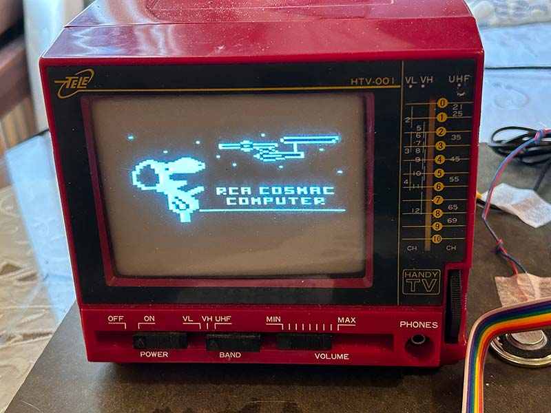
Figure 1 - Emulated COSMAC VIP graphics displayed on an old black & white cathode ray tube TV.
I was lucky to find that picture from the interweb so I could display it with my emulator on my nice little B/W TV.
If you’re interested in this, the rabbit hole for the RCA 1802 on the Web is quite deep; just dive right in. You’ll find several emulators, old programs, new programs, compilers, and development environments. I was particularly tickled to find a C-cassette emulator that can play back COSMAC programs stored as sound on a cassette but do it from binary code files on an SD card.
Someone even wrote a spreadsheet (yes, for that 64x32 pixel display!) as a speculative proof of concept in the spirit of ‘what-if’ instead of using the the VisiCalc program that had been written for the Apple II. If you don’t know, VisiCalc was the original spreadsheet that really launched the micro computer revolution. For the first time ever, it enabled a small one-man business to own a computer to do accounting and billing.
COSMAC was based on the CDP1802 CPU created by Joseph Weisbecker of the RCA Laboratories who almost single-handedly, it seems, created the CPU design, envisioned the home computer revolution not unlike that caused by the Commodore 64, and tried to make it happen. If only the RCA management had been up to the task.
Introducing PICOSMAC
Retro computing seems to be a trend and with so many emulators available for many ancient computers, you may well ask do we really need yet another one. I’ll let you be the judge of that. However, this project is different from running an emulator on a Raspberry Pi with a modern LCD color screen.
PICOSMAC accurately emulates (on a Microchip PIC18F4550) both the CDP1802 CPU and the CDP1861 video chip running at 1.75 MHz — just like the real thing. It runs verbatim the original machine code and produces composite video in the original format. It includes the monitor ROM from 1977 and has 1.5 kB of RAM available for 1802 machine code or CHIP-8 programs. And it’s all done in software.
You can put this together in a day on a breadboard for less than $20. If you buy an obsolete B/W TV from a yard sale, you can convert it into a CRT monitor. Attach a C-cassette recorder and you can get a unique experience that nicely mimics what I experienced back in 1978. Generating video with software is nothing new; you can do that with Arduino.TV. However, there is no 50 year old arcade style game code you can run on an Arduino.
This emulator can run CHIP-8 games (memory space allowing) which is not unique, but this emulator actually runs the CHIP-8 interpreter written in 1802 machine code with timng in every respect almost identical to the original COSMAC VIP.
If a PIC with more memory is used, it should be able to run the original TinyBASIC (Teletype not included).
To get this running, all you need is a PIC18F4550, a 14 MHz crystal, a couple of resistors, and four capacitors, plus a 5V supply and a PICKit2 to program the chip. Add a LED, four resistors, an NPN transistor, and speaker, and you can generate annoying digital beeps.
Throw in an op-amp and some resistors and capacitors and get a feel of just how unreliable C-cassette based storage was.
You can see my Mark II prototype in Figure 2 which I put together in a couple of hours.
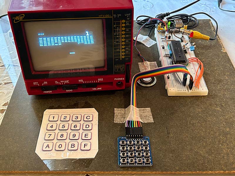
Figure 2 - The complete 1802 emulator running the CHIP-8 game ‘brix.’
Truth be told, I see this project more as a novelty than a serious COSMAC replacement at this point in time because of the limited RAM memory. There are PIC18F processors with more memory, so there’s hope to expand that.
Ye’ Olde CRT
For the authentic look and feel, I really wanted an old Cathode Ray Tube (CRT) based display; preferably a small one. The TV in the photos is something I bought for $20 from an online flea market some years ago with the intention of bringing my original Telmac (a Finnish knockoff of the COSMAC) back to life.
This particular TV didn’t have a video input, and I didn’t want to construct a modulator that could turn the video signal into a TV signal (although you can easily build one from a CMOS 4069). So, I modified this with help from a great friend and wizard in all things analog and digital. (Thanks Christian!)
I suspect many small B/W TV sets are built around the KA2915 chip. I couldn’t find the schematics for this particular TV but the KA2915 datasheet has an example application note which was enough.
All we had to do was remove a resistor to get rid of the TV video signal that comes out of pin 5 and connect my video to the disconnected trace. The video signal levels (2.1 Vpp) at this point are not standard (1.3 Vpp), but with a little experimenting, I found resistor values that allowed the TV to sync to the signal.
Figure 3 shows the modification I made.
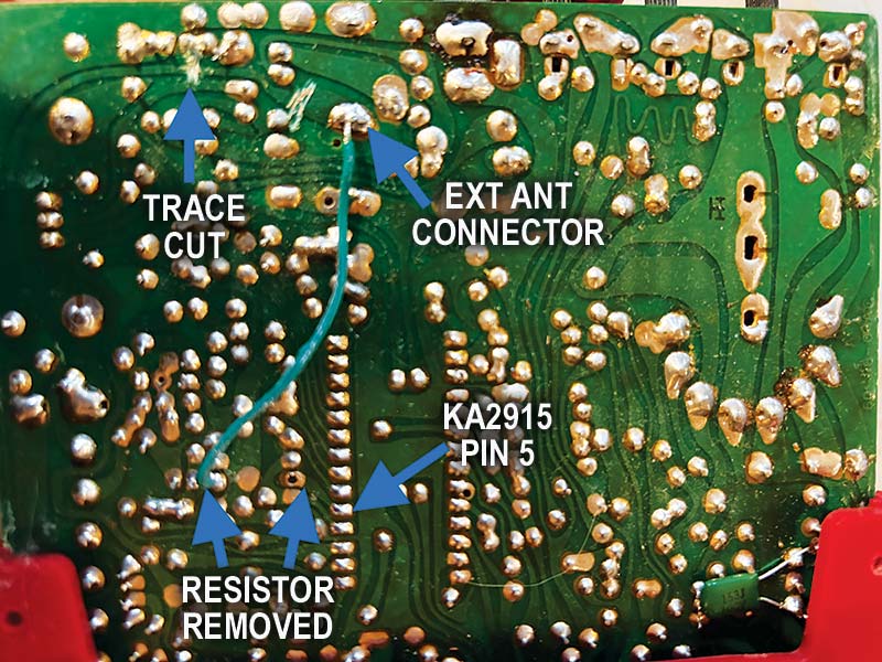
Figure 3 - Modification I made to my TV to allow video input.
I was even able to repurpose the antenna connector as video input by cutting a trace and adding a wire. I opted not to use the built-in speaker for the sound.
With old second-hand CRTs, it’s worth remembering that eventually the filament will wear out and a static image may have been burned into the phosphor screen.
CRT Technology Uses Lethal Voltages!
The acceleration voltage (the thick cable that goes to the side of the CRT tube) can be as high as 35,000 volts! That high voltage also produces X-rays which may be harmful.
The voltages can persist even for a period of time after power has been removed.
Never modify old TVs that have AC power input to accept video signal as the circuitry inside is likely connected to the live wire of the wall socket.
AliExpress Has the Parts
My original Telmac had a 16-key keypad that was nothing more than a PCB (printed circuit board) where you shorted pads with your finger! That worked back then because of the then brand-new CMOS technology. It would probably work with this emulator too.
However, with a 16-key Arduino keypad for $1 from AliExpress, why not save yourself some pain.
While you’re at AliExpress, also grab the 14 MHz crystal. None of the usual suspects had this frequency in stock.
You can even find a NOS (New Old Stock) B/W cathode ray tube monitor (the back illuminated kind) that used to be utilized in doorbell cameras before LCD screens took over; see Figure 4.
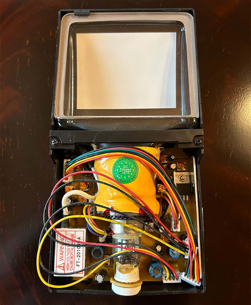
Figure 4 - NOS backlit CRT from AliExpress originally made for doorbell cameras.
I bought one for $15 in case I want to build a super cool handheld ‘Gameboy’ based on my emulator one day.
Building It
The schematic for the circuit is shown in Figure 5.
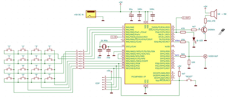
Figure 5 - The emulator schematic.
I made the prototype shown in the photos on a breadboard, but in my opinion, that’s not convenient nor is it reliable. I recommend a Vero board construction which is faster, cheaper, and reliable. I toyed with the idea of a PCB but decided not to create one because if this project has any future, a different chip in a different package with more memory is in the stars.
The minimal setup you need to get this running is the 1...10K ohm pull-up for the reset (MCLR) signal, a 14 MHz crystal, and two 15...27 pF capacitors and three bypass capacitors for the VDD supply pins.
Try to minimize the distance between the bypass capacitors and the VDD/VSS pins and the connections between them (there are two sets of VDD/VSS pins).
Also wire the crystal and the associated capacitor as close to the pins as possible.
A proper power supply with bypassing plus a good crystal oscillator are the most important things in getting any MCU to run reliably or at all. In other respects, the layout of the components isn’t critical since everything critical is inside the single-chip MCU.
To get the emulator code into the PIC, you need an ICSP connector, i.e., a six-pin header and a programmer. I use the PICKit2 and that should work out-of-the-box.
Add three resistors that convert the two output port digital signals into composite video and you’re ready to start testing. Try to minimize wire lengths here also and use a shielded coaxial cable for the video. It probably works regardless, but the video signal easily picks up all kinds of noise which is then visible on the CRT screen.
Eventually, you’ll probably want to have a keypad, so might as well wire that in now. You get the nice Snoopy picture without the keypad, but you can’t select or play any of the CHIP-8 games.
As mentioned, an Arduino 16-key keypad is cheap and cheerful but a little small for my fingers. At a pinch, you might get away with a piece of Vero board where you use your fingers to ‘short circuit’ traces in place of actual keys. As I recall, that was very annoyingly unreliable and the original debounce code in the monitor ROM software was not that great.
The speaker can simply be connected through a >240 ohm resistor to a 4-8 ohm speaker, but I recommend the simple transistor amplifier shown in the schematics for audible sound.
The cassette storage requires an op-amp circuit which I planned to copy either from Telmac or COSMAC VIP schematics. When I asked Christian which one to use, he said that they both looked awful! So, he came up with a much simpler design shown in Figure 6.
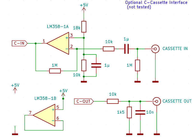
Figure 6 - Cassette interface schematic.
That has not been built, but according to SPICE simulation, it works should you insist on building it.
For the CHIP-8 games built into the emulator, you don’t need the cassette interface. If I want to try something other than those games, I just use the PICkit to re-program the PIC chip.
Running the Emulator
To run the emulator, you need to program the PIC with a PICkit. The emulated 1802 code needs to be ‘backed’ into the .hex file you ‘Flash’ into the chip. I provide a ready-to-Flash and run.hex file with a handful of backed in demo programs in the article downloads.
The process of ‘baking in’ existing 1802 machine code or CHIP-8 code is beyond the scope of this article, so full instructions are provided with the code.
Note that you will need to remove the PICkit for the keypad to work, because the keypad interface uses the same pins as the ICSP in PORTB. I could have used some other port, but I wanted to use PORTB because it has internal pull-up resistors which are needed to make the keypad interface work.
Once the code has been Flashed into the PIC, you just need to power-cycle or reset the PIC.
You should immediately see the Snoopy looking at the Starship Enterprise from Star Trek.
If you hold down any of the 1...6 keys while you reset the PIC, a copy of one of the 1802 / CHIP programs backed into the emulator code in Flash memory is copied into the RAM memory before the emulator is started.
If you hold the C-key on the keypad while you power-up the emulator, it will run code from the emulated COSMAC monitor mode ROM built into the emulator. You can then read/write memory and save/load it to/from the cassette using the keypad.
With the monitor mode, you can even examine and debug the hex code loaded into the RAM as per above.
Since the emulator uses the original ROM code, you can use the original instructions; just search for the RCA COSMAC VIP CDP18S711 Instruction Manual.
How This Project Came into Being
This project has long roots. I got my first computer in 1978; the Finnish knockoff of the RCA COSMAC VIP called the Telmac 1800 mentioned earlier. At that time, it made a big impression on me because it had graphics as opposed to the seven-segment displays that most kits I could afford had.
The things I painfully and slowly learned, and the friends I made paved my path to where I am today.
COSMAC was based on the CDP1802 processor which went nowhere fast — both physically and as a product.
The CPU ran at 1.76 MHz and used 16 clock cycles to execute one instruction for a whopping hundred thousand instructions per second performance on an architecture where a single instruction didn’t do much. On the positive side, it was very easy to program in machine code even without an assembler because of the very symmetrical and clever instruction set and register structure.
A few years later, IBM chose Intel 8088 and Microsoft DOS for the IBM PC and the rest is history. (Painful history for a meritocrat like me because neither was very good, let alone the best choice.)
This left RCA, Motorola, et al., to try to make it in the embedded and emerging gaming world. They did develop some nice MCUs.
Among the chips I got to know was the MC68HC11 which was basically a 6800 eight-bit CPU running at 2 MHz with a bunch of peripherals thrown in. Among the peripherals, there was the then-new SPI or Serial Peripheral Interface, which is, when you get down to it, just a glorified shift register.
One day back then, I realized that the CDP1861 video chip on my Telmac put out video at 1.76 MHz and that the 68C11 SPI could output bits at the same rate. Now how cool would it be if that single-chip MCU would output video, any video!!! An arcade game like Pong in a chip!
Now, that idea never went anywhere because the exponential Moore’s Law saw to it that any trivial idea like that would be superseded by better and cheaper chips every year.
Fast forward 40 years, and I find myself on a holiday at Gran Canaria, waiting for the sunrise, looking for a little project to fill my mornings between my first cup of coffee and my wife waking up.
Reading through the PIC18F4550 datasheet, it suddenly dawned on me that the Master Synchronous Serial Port (MSSP) in it supports an SPI mode. I had a small prototype board with that very chip on it with me and so a little project to create some video in software was born.
It turned out to not be as trivial as stuffing the transmit register with video data as fast as possible, but in the end, I got it to work.
That PIC ran at 12 MHz which, when divided by eight, generated an SPI clock of 1.5 MHz which was my pixel clock. I mused that if I put out 12 bytes of data, this would lead to a 15.625 kHz line frequency which just happened to be the PAL video line frequency!
At this point, the project spiralled out of control.
I recalled that the COSMAC 1802 CPU took 16 clock cycles at 1.75 MHz to execute a single instruction and that the accompanying video chip (CDP1861) output eight bytes of video data per line using DMA, and executed three instructions between video bursts. The PIC processors can do 12 MIPS. The numbers started to go round and round in my head and a crazy monstrous idea emerged from the murky depths.
If I overclocked the PIC to 14 MHz, then I could use 128 PIC instructions to emulate one 1802 instruction and get the emulation to run at 1.75 MHz. At this clock frequency, 14 bytes would equal a 15.625 kHz line frequency and 14 was exactly the number of cycles that the 1861 video chip used to produce one line of video.
This was a sign and just too tempting to ignore.
I had to create an emulator that could not only run 1802 machine code, but also emulate the 1861 video hardware and do all that with timing compatible with the original COSMAC VIP.
How hard could it be?
The Game was On
At this point, this got to be very serious. The gauntlet had been thrown and the challenge accepted.
I felt I was uniquely qualified for this because I knew 1802 almost by heart and I’m very familiar with PIC assembly language tools. Plus, I’m a veteran embedded software developer. It would a shame to waste the opportunity.
To write an emulator is trivial. To make it 100% correct and compatible so that it can run 50 year old software is challenging and a lot of work. To make it all within the timing constraints that I had set for myself, was on another level.
I realized from the start that just writing the code and manually testing and verifying it would not cut it. Especially since I was going to write time-critical machine language code to exactly and accurately simulate executing a different machine code and run it in a single-chip MCU with next to no debugging facilities.
So, I needed a strategy.
The Winning Strategy
My strategy was to write a set of test cases in 1802 assembly language, compile them into machine language, and execute the compiled tests both in a 1802 simulator running on my Mac and in the 1802 emulator I was writing for the PIC, and compare the results.
Fortunately, I knew from the past that my gpsim project had produced a PIC simulator that could be used to debug the PIC code, and which could be run from the command line. Thus, it could be integrated into an automatic regression test setup.
I couldn’t find a 1802 simulator that would have been easy to incorporate, so I wrote my own 1802 simulator in Java. To tell the truth, I didn’t search that hard. Writing simulators is always fun, if not always advisable.
Writing a simulator to verify an emulator being written is an obvious chicken and egg problem. How do I make sure my simulator is correct?
I solved this by creating the simulator functionality directly and automatically from text I copy and pasted from the 1802 datasheet.
I also assumed that since the simulator is automatically generated Java and the emulator is handcrafted PIC assembly language, it was unlikely that I would make the same errors in both. So, if the simulator and emulator results agreed, then both were likely correct.
The automated tests provided me with clock cycle level info about execution time for all the emulated instructions and made sure that the emulator worked and, most importantly, that my optimizations didn’t break anything.
This regression testing ability really came into its own when I was optimizing the emulator code.
I originally thought that having time for 128 PIC instructions to emulate one 1802 instruction was plenty.
It turned out that after all the nitty gritty details were in place, I was seriously over budget at emulating many instructions.
Several times during the optimization, I spent days to find a way to get rid of just one more PIC instruction. Without the fully automatic regression testing, I think I would have had to give up.
How the Emulator Works
The basic principle of an emulator is simple. It’s just an infinite loop that fetches an instruction from the memory location pointed to by a program counter, advances the program counter, and then branches to an instruction-specific handling routine.
To make this run at a constant speed or clock frequency like a real CPU, this needs to be called from a timer or some such interrupt.
In my emulator, the emulation is driven by an SPI transfer completed interrupt.
This interrupt is triggered after eight bits have been shifted out, i.e., after every eighth pixel. Since the SPI clock is driven by a signal derived from the CPU clock divided by eight, we get an interrupt every 64th PIC CPU instruction cycle. This sets a hard limit to how many instructions can be executed in the longest path through the interrupt handling, i.e., the emulation code.
The emulated 1802 uses two eight-clock-pulse-long cycles to fetch and execute one instruction. The emulator uses one interrupt cycle to fetch an instruction to be emulated and pre-calculate the dispatch address for the execution, and in the next interrupt jumps to the precalculated handling routine.
This matches perfectly how the real 1802 CPU works and makes the timing very, very compatible.
Interrupt Considerations
Throwing in the video emulation adds a very strict constraint because the video signal is very unforgiving — especially with the kind of good old CRT monitor I wanted to use. Even small deviations from the ideal timing are easily visible on the screen.
Without the video, it would be enough if the emulator would use 64 clock cycles or less on average for the emulation, but successful video generation requires that this hard limit is never exceeded.
First of all, this means that there can be no other interrupts; only one periodic interrupt that drives the emulation forwards. Those familiar with PIC architecture may think that a low priority interrupt could be used for secondary tasks. I tried it, it won’t work. It messes up the timing.
Secondly, we need to consider interrupt latency. Latency as such is not problem but any jitter, i.e., variation in latency, is a problem.
According to the PIC datasheet, the latency varies between 3-4 instruction cycles, i.e., the jitter is one cycle. Given that the pixel clock is a PIC instruction clock divided by eight, we immediately see that the jitter is 1/8th of a pixel horizontally, which should be visible.
However, I couldn’t see any evidence of this jitter; not on the CRT screen nor with an oscilloscope.
To understand why this can be so, even though the datasheet says otherwise, we need to dig deeper into how a CPU works.
Most CPUs never interrupt an instruction; interrupts can only happen between instructions. This means that, depending on which instruction the main program is executing, the interrupt latency will vary.
To alleviate this problem, my main program is a single instruction that loops onto itself:
mainloop:
BRA mainloop ; executes only one instruction in a loop
Thus, interrupts can only be delayed by that one instruction execution time, which is constant.
This alone does not guarantee jitter-free interrupt service as the interrupt source itself can run asynchronously to the CPU. To have any hope of success, the interrupt source needs to run from the same clock as the CPU and have a period that is an exact integer multiple of the pixel clock.
At one point when I ran out of cycles, I thought I could use a higher CPU frequency and divide it down more for the SPI/pixel clock to execute more instructions per interrupt. Turns out that unless the SPI clock pre-scaler is exactly eight, the SPI interrupt has a lot of jitter that ruins the video. I sometimes missed the time slot to put out more video data.
Producing Video with SPI
Like I mentioned, monochrome video generation is basically just a shift register, and an SPI interface is just a glorified shift register that shifts out eight bits after you load the transmit register with data. I know Arduino TV does this without a shift register but that leaves NO room for executing anything else during the video output. So, where would I emulate a CPU with that approach?
My first attempt was to configure the SPI to run a CPU clock divided by a pre-scaler of eight and just send all ones bytes, i.e., 0xFF, every time I got a transmission complete interrupt. Unfortunately, this didn’t work. Apparently, there’s some mechanism that causes a delay between consecutive bytes and it’s not possible to send data back-to-back, so to speak. In practice, this resulted in gaps after every eigth pixel horizontally.
At first, this was a showstopper. Fortunately, that was very early in the project, before I had invested a lot of time. Shows you the importance of doing fundamental tests before you embark on a journey.
But then I had a brain wave. My test was done in SPI MASTER mode. How about SLAVE mode?
By definition, slave mode timing is totally controlled by the Slave Select signal and clock from the Master, so for that to function at max SPI speed there couldn’t be any extra delays.
I tested this hypothesis and it worked!
Of course, I didn’t want to have an extra external circuit to generate the SPI clock that (in Slave mode) is supposed to come from the Master. So, I configured TIMER2 to produce a PWM signal at 1/8th of the CPU clock and (with a wire) looped back the PWM signal from the CCP2 output to the SCL clock input.
I could now produce a constant stream of pixel data at 1.75 MHz.
To give you an idea how critical the timing and execution paths are, let’s have a look at how the video data is sent in the interrupt:
hi_prio_int: CODE 0x000008; place the code at high priority interrupt vector
MOVF INDF2, w ; get next video byte to output
MOVF VIDEO_CNTR, f, b ; check if all video bytes are done
BZ video_done ; branch if done
MOVWF SSPBUF; set the video data ready for the Master to clock out
This is exactly as many instructions and execution time there can be; any less and I couldn’t accomplish what needs to be done, any more and the timing doesn’t work. If you miss the time slot to re-load the SSPBUF, then the SPI shifts out only zeros.
I was also very lucky in that the SPI interface shifts data out MSB first just like the 1861 video chip. There’s no room in the above code for bit order swapping. It can’t be done anywhere else as the 50 year old code that the emulator executes expects this bit order.
Instruction Dispatching
Emulation (that is, decoding of the instruction set) utilizes a computed goto method that the PIC offers. This is customarily done via a jump table. You first calculate an index (based on the emulated opcode being executed) and then jump into that index in the table where a secondary jump takes you to the actual place you want to jump to.
The problem was that this introduced an extra instruction which I couldn’t afford. Other methods often used in more conventional processors architectures such as manipulating the return address in the stack or self-modifying code are even slower.
So, what my emulation code does is it takes the 1802 opcode, multiplies it by 64, adds 0x4000 to it, and jumps to that address. The opcode 0x00 is handled in address 0x4000; opcode 0x01 in 0x4040; opcode 0x02 in 0x4080; and so on.
This requires that every single one of the 256 opcode needs to be manually placed at the correct address like this:
ORG 0x4000 ; place following code at 0x4000
opcode_00: <handling of 00 here>
ORG 0x4040 ; place following code at 0x4040
opcode_01: <handling of 01 here>
Besides saving one instruction execution time, this has the benefit that because the instruction emulation code has a strict time budget of 32 clock cycles per interrupt and the PIC executes one instruction per clock cycle and uses one word per instruction, all the emulation code needs to fit in that 32 instruction slot between handling codes for different opcodes, giving me an automatic compile time failure if I overspent.
However, this had an unforeseen side effect that caused a lot of grief and more work.
Using an ORG like above creates gaps in the code in memory which result in the gpasm producing a ‘section’ for each piece of code. Now it turns out that gpsim fails if there are more than 256 sections in any program it simulates! The code still executes correctly on the real hardware, but the simulator does not load the code correctly and thus fails. To fix this problem, I had to manually fill enough of those gaps with NOP instructions that bring the section count down.
Not only was that a lot of manual work as the assembler can’t help with that, but it’s also fragile because any modification to the emulator code may create gaps that then may break the simulation — which is a nuisance to track down.
Video Generation
Generating video involves more than just shifting out the actual data. You need to also generate vertical and horizontal sync pulses and, in the case of 1802/1861, an emulated interrupt and a crucial internal sync signal needs to be generated.
A classical video signal is made up of lines that make up the picture on screen. The cathode ray beam scans the screen from left to right and top to bottom 50/60 times per second, and the signal level determines the intensity of that beam and hence the intensity of the light at spots where the beam hits a phosphor screen.
In a CRT monitor (and TV), there are saw tooth oscillators that control the beam and these need to be synchronized with the video signal. Otherwise, the picture will roll vertically or slant horizontally. Many modern LCD monitors can still use this signal, but the process is totally different from the CRT monitor.
Figure 7 shows the format of a composite video signal corresponding to a single line on a CRT screen.
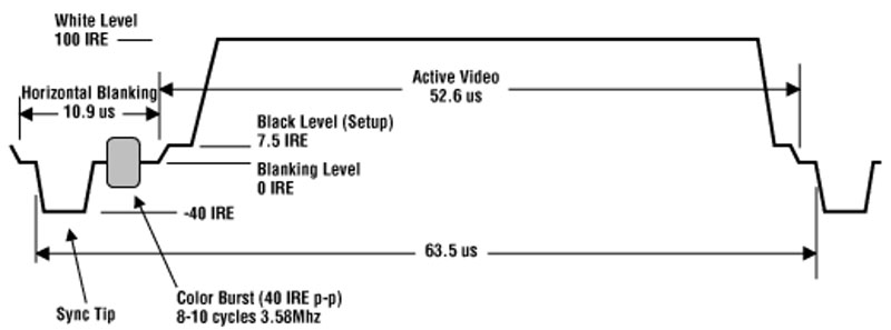
Figure 7 - Composite video signal format.
The signal levels are specified in terms of 140 IRE = 1 Vpp.
The line starts with a line sync pulse at zero level. It then rises to what is called the black level and the actual graphics then ride on top of that, alternating between the black and white levels. The B/W levels are not that critical as the monitors have brightness and contrast adjustments, but the sync pulse level and the overall timing is critical for the monitor to synchronize.
The color burst is optional and only necessary for a color image. If we could generate the burst, we could actually produce limited colors even from B/W signals by carefully selecting pixel patterns. This trick was used on the Apple II. Alas, we can’t create the color burst in software in the PIC18F4550. (Well, if we used a 17.73 MHz crystal and set the SPI clock to half of that, then perhaps ... I will leave this exercise to the reader.)
The video timing is generated by the SPI outputting data a byte at a time and generating an interrupt at 1.75 MHz / 8 = 219 kHz or every 4.57 µsec. The actual video data is the data shifted out from the SPI Master In Slave Out (MISO) output.
The SPI actually churns out data all the time — even during the black image margins — and sync pulses to maintain the sync and run the emulation. Unless fed with new data, however, the SPI outputs what it has read in from the Master Out Slave In (MOSI) input. This input is connected to ground, so in the absence of video data, zeros are clocked out.
The line sync is generated from an output port signal by holding it down for one interrupt period and keeping it high for the rest of the line. During vertical syncing, the polarity of the sync signal is inverted, i.e., it still runs, but most of the time the signal is at a low level and the line syncs appear as positive pulses one interrupt cycle long.
The video signal from the MISO and the sync signal from the outport are summed with three resistors to produce the sync, black, and white levels.
Figure 8 shows the actual signal generated by my prototype running the emulator captured with an oscilloscope.
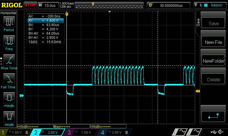
Figure 8 - Video signal from the prototype.
This is actually one of the lines from the graphics of the CHIP-8 game brix shown on screen back in Figure 2. The individual bricks can be seen on that oscilloscope picture (those are not individual pixels but groups of four pixels: one black, three white). Note that the voltage levels in my setup don’t match the standard as my modified TV is not compatible with standard video.
The CDP1861 video chip produced horizontal timing compatible with NTSC compatible video. PICOSMAC emulation produces PAL compatible video. The main difference between them is the number of lines in a frame. PAL uses 312 lines and NTSC uses 262 (ignoring interlace). This is because of the 50 Hz / 60 Hz difference between US and Europe.
You can configure the number of lines in the software to make it NTSC compatible. In COSMAC, there was actually only 128 lines of graphics data, so the number of lines in a frame makes little difference as long as the display syncs.
In PAL video, a line is 64 µsec long and in NTSC it’s 63.5 µsec. This is such a small difference that it makes no difference.
Implementing Video
To implement the video timing, I utilized a variation of a coding technique that was often used with the 1802 and which is now popularly known as a coroutine.
This allows you to write code as a linear (or looped) sequence of statements but suspend the execution for a different task and then continue the original flow of execution where it left off.
This allowed me to write, for example, the complete video generation (excluding vertical sync):
REPEAT VCOUNTER, VIDEO_LINES ; prepare to loop all the video lines
video_loop:
SET_SYNC 0 ; set sync out to 0 for one 4.7 usec interrupt period
YIELD ; wait for next interrupt
SET_SYNC 1 ; end sync pulse
REPEAT HCOUNTER, PRE_BYTES; prepare to loop for the ‘porch’ part of the line
loop_pre:
YIELD ; wait for next interrupt
LOOP HCOUNTER, loop_pre ; loop until porch over
START_VIDEO ; actually output of 8 bytes hidden in macro
REPEAT HCOUNTER, POST_BYTES ; prepare for ‘back porch’
loop_post:
YIELD ; wait for next interrupt
LOOP HCOUNTER, loop_post ; loop until back porch done
LOOP VCOUNTER, video_loop ; loop until video done
Even without knowing what the macros REPEAT, LOOP, and YIELD do, this code should look simple and understandable, yet incomprehensible when you consider that this runs inside an interrupt.
REPEAT and LOOP are just two simple macros that set up a counter, decrement, and test it, providing a simple FOR loop mechanism for the PIC assembly language:
REPEAT MACRO counter, count
MOVLW count
MOVWF counter, b
ENDM
LOOP MACRO counter, label
DECFSZ counter, f, b
BRA label
ENDM
The trick that makes the looping possible inside an interrupt is in the YIELD macro:
YIELD MACRO
LOCAL label
MOVLW HIGH(label)
MOVWF GO_NEXTH, b
MOVLW LOW(label)
MOVWF GO_NEXTL, b
RETFIE
label:
ENDM
What this code does is it first makes a note where the execution should continue the next time an interrupt occurs and then it just returns from the interrupt.
The interrupt handling has this code:
MOVFF GO_NEXTH, PCLATH
MOVF GO_NEXTL, w, b
MOVWF PCL
which fetches the stored continuation address and jumps to it by manipulating the program counter, much like the computed goto mentioned earlier.
START_VIDEO is a macro that sets up a counter for eight bytes and as long as that counter is not zero, the interrupt handler loads data from the video memory pointer to the SPI transmit register and decrements the counter — only after the counter reaches zero does the control flow ‘return’ from the START_VIDEO macro.
The listing shown here isn’t verbatim from the emulator code because there, this technique is used twice as it’s not only necessary to keep track where the video generation left off, but it also tracks where the CPU code emulation left off. It looks more complicated if you view the actual source code.
The point of all the above is not only that it allows the code to reflect the essentials of the control flow instead of getting bogged down in the machinery, but also that this is the most efficient way to implement a large state machine in a PIC processor.
A classical state machine implementation would use several more instructions, use more space, and the code layout would reflect the state machine mechanism and not what the code is accomplishing.
The Genius of 1802/1861 Duality
You may wonder why I’ve gone to such lengths at emulating the 1802 instruction execution even to sub instruction timing level.
This is because the original 1802 processor and 1861 video generator worked together in a very intimate way to produce the video with minimum transistor count and thus silicon wafer area.
The 1802 CPU provides the video data from the system RAM memory using a very simple DMA mechanism where the CPU gives the DMA address from its register R0 and the 1861 video chip captures the data from the data bus and shifts it out of the video output. The video chip is not involved in the DMA address generation and beyond incrementing the DMA address, neither is the CPU.
It’s the video service interrupt code that is carefully and cleverly crafted that takes care of manipulating the R0 register so that the correct addresses are generated in sync with the video generation.
This requires, for example, that from the interrupt signal that notifies that graphics that data is needed soon, there must be exactly 29 CPU cycles to setting up the first DMA address in R0. After each eight bytes (64 pixels) that make up a video line, there has to be exactly three (emulated) instructions to update R0.
By carefully manipulating the R0 register, different vertical resolution can be achieved.
The ‘standard’ video interrupt handler routine in the COSMAC monitor ROM produces more or less square pixels by repeating each video line four times. This conserves memory as the whole 64x32 pixel graphic only uses one page or 256 bytes of memory then.
The Snoopy picture program shown back in Figure 1 on the other hand contains an interrupt routine that only doubles each line which creates graphics in 64x64 mode with pixels in an aspect ratio of 2:1.
It’s also possible to use a 128x64 pixel mode.
If the emulation isn’t correct to that level of timing, then none of the old graphics code from 50 years ago will work without modification.
Bends in the Road
One of the problems I didn’t anticipate was how complicated it was to emulate accessing memory — especially reading ROM memory.
My first thought was to use the PIC RAM to emulate COSMAC ROM but this particular PIC (actually all of them in this series) has precociously little RAM (only 2 kB) and all of that is needed to run even the smallest emulated programs. My original Telmac had only 1 kB and COSMAC VIP had up to 4 kB of RAM plus 512 bytes of ROM, which contained (among other things) the all-important video interrupt and keypad read routines.
In a PIC, access to ROM memory, i.e., the Flash memory that hosts the PIC code (and thus the emulated ROM code), is cumbersome and slow because of the Harvard architecture. To access the Flash, you need to program the address into three eight-bit registers, perform a special TBLRD instruction, and read the fetched Flash data from the TABLAT register.
On the other hand, 1802 is not Harvard, so depending on the address range accessed, the emulator needs to either read from RAM or ROM (Flash). Moreover, that address range on the COSMAC depended on whether or not an external flip-flop that forced address line A15 had been cleared with an INP 1 instruction or not.
All that required many instructions in the emulator and ate up a large portion of my 32 instruction timing budget:
read_mem ; Register num that points to memory in W on entry
RLNCF FSR0L, f ; Double the reg num cause regs are two bytes wide
MOVF PREINC0, w ; move RN.1 to W
IORWF FORCE_A15, w ; OR address modifier
BN rom_read ; if RN >= 0x8000 then this is ROM address
ram_read
MOVWF FSR1H ; move it to the FSR1H
DECF FSR0L, f ; read RN.0 move it to the FSR1L
MOVFF INDF0, FSR1L ; leave PSR0 to point RN.0
MOVF INDF1, w
BRA read_done
rom_read
ADDLW HIGH(ROM_ADDRESS-0x8000); add the ROM start address
MOVWF TBLPTRH ; set the table pointer high address
DECF FSR0L, f ; read RN.0 move it to the FSR1L
MOVFF INDF0, TBLPTRL ;
TBLRD * ; read the data from ROM to TABLAT
MOVF TABLAT, w ; move the ROM data to W
read_done
Final Beep
The last feature I needed to add was a simple ‘beep’ sound generation.
Unfortunately, my PIC didn’t have any suitable hardware timer I could use to generate the sound. So, it would have to be done in the already crowded interrupt where everything from video generation to CPU emulation happens.
If video generation can’t tolerate any jitter, generating sounds is not much more forgiving.
Plus, my clock cycle budget — after all the optimization I had already done — only had room for two more instructions!
I was quite proud of myself when I found the solution.
Two instructions were enough to decrement an eight-bit counter in every interrupt and toggle an output when it overflows, like this:
DCFSNZ BEEPCNT, f, b ; decrement BEEPCNT, skip next if not zero
BTG BEEP_PORT, BEEP_BIT ; toggle output port connected to the speaker
The emulation interrupt runs at 1.75 MHz/8, and the above code divides that by 256, so toggling produces a frequency of 427 Hz which is very reminiscent of those old beeps.
I couldn’t fit the code to make the sound obey the Q-LED output which controlled an external oscillator in the original COSMAC.
However, in the code that emulates the 1802 opcodes that set/clear the Q-LED output in the emulator, I found room to change the processor pin direction between input and output and thus the sound can be continuously generated. However, it’s not audible when the pin is in input mode like this:
opcode_7A: ; 1802 opcode 7B is RESET Q
BSF REG_Q, 0 ; clear emulator internal Q-flag
BSF QLED_PORT, QLED_BIT ; set Q-LED to 0
BCF BEEP_TRIS, BEEP_BIT ; configure the sound pin as input
opcode_7B: ; 1802 opcode 7B is SET Q
BSF REG_Q, 0 ; set emulator internal Q-flag
BSF QLED_PORT, QLED_BIT ; set the Q-LED to 1
BCF BEEP_TRIS, BEEP_BIT ; configure the sound as output
Getting the Emulator Code
I have open sourced the code; it’s available for personal use at https://github.com/nyholku/picosmac. It’s also available in the article downloads.
At the time I wrote this, the code would only run on a PIC18F4550 which is kind of ancient and relatively expensive at around $5.
The Makefile in the downloads has a provision for compiling the code for a PIC45K50 which is more modern and half the price. That’s unlikely to run straight out of the box, unfortunately.
Porting the code to other processors in the PIC18F series shouldn’t be too difficult, assuming the SPI behaves as described.
I do the code development on a Mac, so the tooling I ‘support’ is for MacOS. It should be trivial to run the tools in Linux, and adapting them for Windows should also be totally feasible.
Basically, all that’s needed are GPUTILS and Make tools.
If you want to use the code to convert raw binary CHIP-8 games for ‘baking in,’ you’ll also need Java runtime.
If you want to (but there should be no need to) run the regression testing, you’ll also need gpsim. All of those are available for Linux and Windows too.
Further Development
At this point, I’ve scratched my itch and I’m not immediately going to expand this novelty project. If I do, I’ll add a serial port connection and mode in the emulator that allows uploading 1802 code into the emulator from a PC using a serial port and any standard terminal emulator.
If you need more RAM, then I would suggest looking at the PIC18F46K22 which has almost 4 kB, which would leave about 3.5 kB for the emulated code.
You may be tempted to consider, for example, the PIC18F27Q83 which has almost 13 kB of RAM memory. It should be possible to port the code there, too. However, the tools that I have used don’t support that processor, so the source code will probably need some work to compile them with Microchip’s new MP LAB X tools.
Also note that regression testing (should you like to use that) depends on gpsim which doesn’t support the newer PICs. I can’t name a replacement.
Worth noting is that many of the newer PICs run at 3.3 volts and this may necessitate a simple transistor amplifier for the video signal.
Despite the above concerns, having my PICOSMAC running with 12 kB RAM available for programming on a $2 28-pin chip is tempting.
I hope you found this article entertaining. In our world where everything gets ever more complex, it somehow feels good to go back to simpler times for a moment or two. NV
Resources
Downloads
What’s In The Zip?
Code
Makefile
Instructions For Baking In Process
Demo Programs