Explore the world of tube-type electronics by restoring a classic AM/FM receiver: the Zenith H845/C845.
Many electronics enthusiasts consider vacuum tubes and their bulky, hot, high-voltage circuitry artifacts from a bygone era. After all, you’d need a room packed with thousands of tube circuits to even approximate the computational power of a lowly Arduino microcontroller. However, discerning audiophiles, electric guitarists, and seasoned ham radio operators will tell you that tubes are still the best option for applications where tone and tolerance for abuse are paramount. There’s just something about a vintage Fender guitar amp or a McIntosh tube-type preamp that can’t be matched by modern solid-state electronics. Even the simplest vintage and modern audio equipment built with vacuum tubes and point-to-point wiring can sell for thousands of dollars.
Teardowns of vintage gear in which you carefully note component values, construction techniques, and create a schematic from scratch are a great introduction to vacuum tubes. The next level (and the focus of this article) is to restore tube-type devices, starting with a tabletop radio. Not only will you learn to work with the technology, but you’ll have something of value when you’re done.
Moreover, unlike a typical solid-state radio, a tube-type radio will likely survive the electromagnetic pulse (EMP) of an indirect nuclear event. To take full advantage of the technology, it helps to have an understanding of the basic construction and operation of tube-type receivers, as outlined below.
Tabletop AM/FM Tube Radios
With the proper safety precautions, refurbishing a vintage AM/FM radio is a great place to start your journey into tube electronics. Vintage units vary in stage of disrepair, affordability, and availability. On any given day, eBay lists vintage radio receivers from $15 for domestic AM radios to $1,000 or more for rare, fully refurbished European models with full coverage of the AM shortwave bands as well as domestic AM/FM.
Our focus is inexpensive units described as “working, as-is” which I read to mean “in desperate need of work.”
Zenith H845/C845
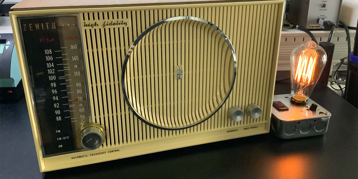
To illustrate the restoration process, I’m going to use a popular Zenith AM/FM superheterodyne receiver from the 1960s: the H845/C845. It’s shown fully refurbished in Figure 1.
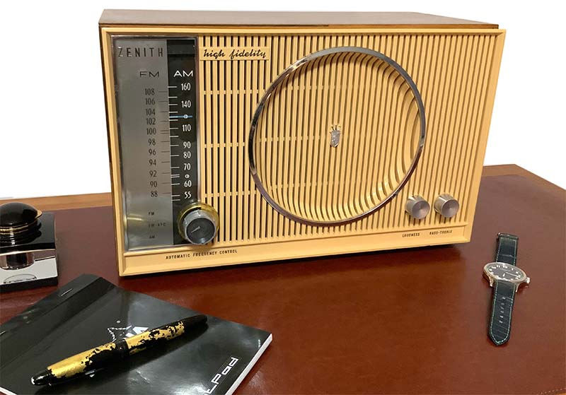
FIGURE 1. Zenith radio after restoration, with dim bulb current limiter, variac, and isolation transformer.
I paid $40 for the receiver (which I’ll refer to from now on as simply the receiver) on eBay, plus another $25 shipping. You don’t have to purchase a particular radio to follow along with this article. You can select from hundreds of vintage radios, preferably from the 1960s. The overall restoration process varies little from model to model in the same time period.
A radio produced in the ‘40s will have a significantly different build — from the type of insulation used on the wires to the value of the coupling capacitors — compared to a radio from the ‘60s.
In addition, if this is your first foray into tubes, then keep it simple and affordable. Avoid the temptation to refurbish your $4,000 McIntosh tube preamp. Better to learn on a disposable radio. I’ll cover the renovation of high-end systems in an upcoming article.
Regardless of the radio you choose, keep in mind that looks are paramount when it comes to restoration. You can hide lots of cold solder joints behind a pretty veneer, but no one wants a dumpy looking receiver on their desk, regardless of performance. Unless you’re into stripping and sanding and painting more than soldering and circuit analysis, then go for the most pristine looking radio you can find that fits your budget.
Functionally, the H845 has a lighted dial and the C845 has an RCA phonograph input in the back of the unit. Otherwise, the models are identical. They share a chassis design, a hardwood veneer case, a plastic front, a 7.5 inch midrange and 3.5 inch tweeter, and surprisingly good sound when fully restored.
It’s easy to find a schematic and parts for these American made radios. Moreover, once you master this radio, you’ll be familiar with the entire line of Zenith tube-type radios, including the C, H, R, W, M, W, and Y series. The eight-tube receiver follows the typical superheterodyne architecture. The selected AM signal is amplified by the RF amp and mixed with the signal from the local oscillator, producing a 455 kHz difference frequency. This intermediate frequency signal is selectively amplified, converted to audio in an AM detector, and subjected to two stages of amplification.
FM signals follow a similar signal path, but use a 10.7 MHz intermediate frequency, an amplitude limiter, and a discriminator to demodulate the signal. The radio has a radio frequency (RF) amplifier for AM and FM, separate intermediate frequency (IF) sections for AM and FM, a mono power amplifier, and a midrange/tweeter speaker pair. The eight tubes and their functions in the radio are:
- 6BJ6 FM/AM RF amplifier
- 12AT7 FM/AM mixer and FM/AM oscillator
- 6AB4 FM automatic frequency control (AFC)
- 12BA6 first AM/FM IF amplifier
- 12BA6 second AM/FM IF amplifier
- 12AU6 FM limiter
- 19T8 FM discriminator and AM detector, automatic volume control, and amplifier
- 35C5 1.5 watt output amplifier
The leading number on a vacuum tube is the filament voltage. For example, the 6BJ6 pentode (i.e., five electrode tube) has a six volt filament, while the 35C5 pentode has a 35 volt filament. The alpha-numeric characters following the leading number are useful in looking up the other tube characteristics, but they don’t in themselves provide any additional data.
A Sam’s schematic shows the pinout of each tube with the nominal voltages. Recall that pin numbering is clockwise, looking from the bottom of the tube. Tubes with multiple separate electrodes within the same glass envelope — such as the 12AT7 dual triode (i.e., three electrode) tubes — are depicted with a dashed line for part of the glass envelope.
Documentation
If you’re a beginner, then don’t even think about restoring a vintage receiver without documentation. A schematic, parts list, identification of parts on the chassis, and alignment instructions are critical for a successful restoration.
Documentation is available online from Sam’s Photofacts ($15) or (if you’re willing to spend a few minutes searching the Web) free from any number of sites. Antique Electronic Supply (tubesandmore.com) — one of my favorite sources for vintage-compatible parts — has an extensive online library of schematics. You can purchase a PDF for $8 or simply view the schematics online for free.
Tubes Can Bite
It’s important to remember that you aren’t dealing with 3.3 VDC logic circuits. Tube circuits in vintage radio sets rely on high voltage that can bite or worse. Use an isolation transformer and never solder or remove components from a live circuit.
INFRASTRUCTURE
A tube-friendly workbench includes a modest selection of capacitors and resistors, as well as a few key pieces of equipment for testing and alignment. Assuming you have a workbench configured for low voltage work — including a digital multimeter (DMM), soldering station, various hand tools, and perhaps an oscilloscope — your first purchases should include an isolation transformer, a variable autotransformer or Variac, a dim bulb current limiter, and a set of plastic alignment tools.
An isolation transformer will help minimize your chances of coming in direct contact with the 117V mains voltage, and the variable autotransformer and dim bulb current limiter will help minimize the odds of your radio going up in smoke.
A plastic alignment tool will enable you to adjust the inductors in the AM and FM signal paths. If you’re adept at eBay and don’t mind a few scuffs here and there, you can acquire this minimum set of equipment for under $100.
Next on the list are an analog vacuum tube voltmeter (VTVM) or equivalent, a capacitor tester, and a function generator. A VTVM or equivalent meter with 10M ohm or more input impedance is handy because the voltages listed on the schematic assume high impedance input.
When I measure grid voltages with my trusty Fluke 87 DMM, voltages are 10% to 15% lower than specified on schematics. Although I own a vintage VTVM, it’s much easier and safer for me to use a battery-powered analog meter with an amplified front end: the Sanwa CX506a multi-tester. I don’t have to worry about whether the CX506a’s shield is at ground level and presents a potential shock hazard.
Many modern DMMs — from $15 disposables to the $350 Fluke 87V — have a built-in capacitance meter. These meters can be helpful in identifying new capacitors and testing used capacitors. Dedicated capacitance testers, or combination LRC testers, are available from $35 to over $400, including a variety of modern and vintage models.
My favorites are the vintage Heathkit IT-11 and Sprague TO-6, which can measure leakage under high voltage. The obvious limitation these vintage models have is space and the need to have them plugged in and stabilized for hours before use. A battery-powered pocket-sized DMM with built-in capacitance meter, in contrast, can always be at the ready.
Standard Values Evolve with the Times
Radios built pre-WWII use different standards for capacitor values compared with radios built after WWII. Your library of components should reflect the year in which your radio was built. Examples of standard values from pre and post war time include the following:
| Pre WWII |
Post WWII |
| 0.0015 µF |
0.0047 µF |
| 0.003 µF |
0.0033 µF |
| 0.004 µF |
0.0047 µF |
| 0.06 µF |
0.068 µF |
THE RESTORATION PROCESS
Restoration is a logical process that begins and ends with careful, detailed inspection of the radio. I’ve used the process outlined below on a variety of tube-type receivers, all with good results.
Inspection — With Your Digital Camera In Hand
Once you’ve unpacked your radio, the next step is a thorough inspection outside of the case. Beginning with the extraction of the chassis from the case, take lots of photos to document where components are located. Note the condition of the power cord. Many early radios (including the Zenith) use non-polarized plugs without a power transformer to isolate the power main from the chassis.
Note the location of the wax-paper capacitors and electrolytic capacitors because they’ll have to be replaced. Similarly, the selenium rectifier will have to be replaced with a silicon version. Check the condition of the speakers. Is the paper cone of the large mid-range speaker torn or mangled? Are there any foreign objects in the speaker? My radio featured a loose bolt and washer positioned to cut into the soft felt center of the speaker.
Check the resistance of the speakers and compare that with the values listed in the documentation. Old piezo tweeters commonly fail and need to be replaced.
Are there signs of abuse by a former technician? Cold solder joints and burned insulation suggest the unit has been worked on in the past. Prior work is more destructive than the passage of time — especially when it involves modification of components.
Locate the vacuum tube map on the underside of the radio and verify that the proper tube is used in each socket. Substituting tubes is common in vintage gear and a common cause of problems. If you have access to a tube checker, then check the tubes for conductivity and shorts. Of course, if you have access to a transconductance meter such as the Hickok 600a, then use it. In a future article, I’ll compare a range of tube testers.
The bulbs on vintage radios are notorious for burning out after only a few months. The two miniature incandescent bulbs in my radio were no exception. Note that replacing only one bulb in a pair will cause the remaining bulb to burn out faster than normal.
Finally, give the unit a gentle shake. Is there anything rattling around that might cause a problem when the unit is plugged in? Loose metal objects will have to be located and removed before power-up. With the bolt and washer attached to the soft felt center in the main speaker noted earlier, playing the unit for only a few seconds would have rendered the speaker useless.
Decision: Parts Bin or Restoration
At this point, you should have a good idea of the cost and extent of the repairs needed to restore your radio. Tally up the cost of capacitors, resistors, diodes, tubes, bulbs, wires, and anything else that needs to be replaced. In my case, there were no signs of major damage, from nature or man. The woodwork of the radio was damaged in places and the tube side covered in dust and fur balls (see Figures 2 and 3), but otherwise the radio was in repairable condition.
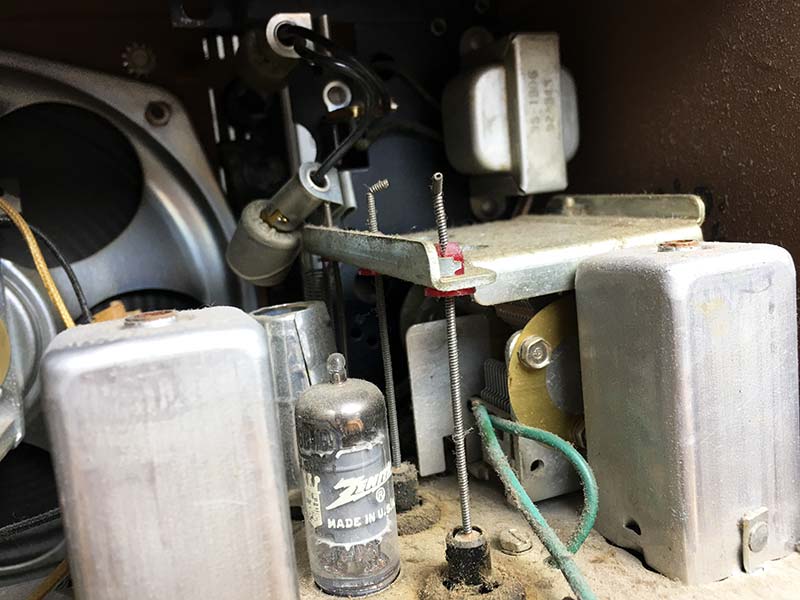
FIGURE 2. First peek after removing the back. Note the dust and grime.
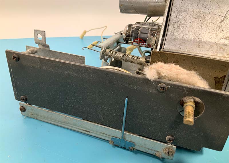
FIGURE 3. Fur ball in the tuning mechanism of the radio.
The component side of the radio had signs of reworking, including a new audio pot and numerous areas of scorched PVC wire.
Cleanup
The next step is cleanup. The component side of my radio was covered with electrical spray residue, which I removed with a quick dousing in CRC QD Electronic Cleaner spray, followed by cotton swabs soaked in isopropyl alcohol. The CRC QD cleaner evaporates completely and — unlike many electrical cleaners — is safe to use on plastics.
The tube side of the radio looked as though it had been the home of a small animal, and a yellow residue on the inductor cans suggested that it was also in the home of a smoker. I used Super Clean to remove the residue, quickly followed by blasts of compressed air to move debris and prevent oxidation of the metal chassis.
I kept the plates of the main tuning capacitor fully meshed during cleaning to minimize the risk of damage to the capacitor. Figures 4 and 5 show the tube and component sides of the radio after cleaning, respectively.
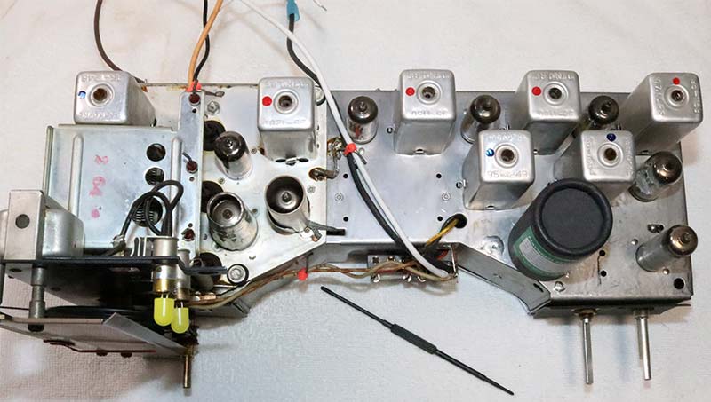
FIGURE 4. Tube side after cleaning. Note plastic tuning tool in front of unit.
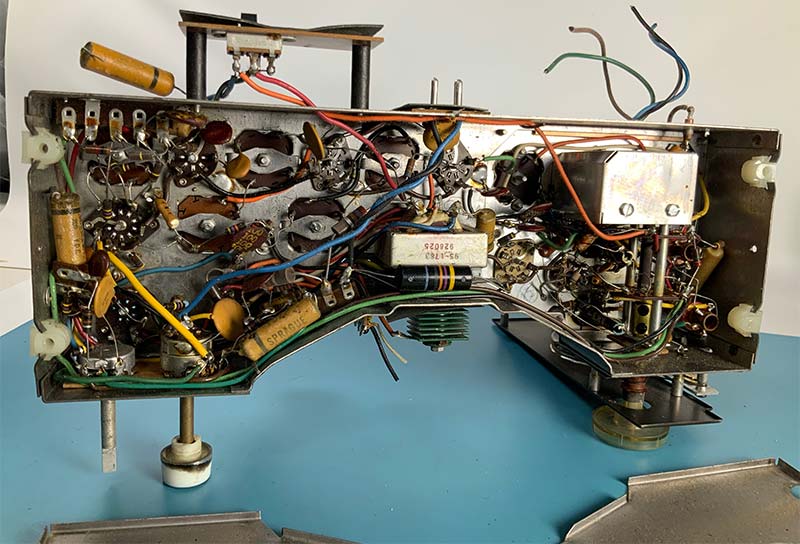
FIGURE 5. Component side after initial cleaning.
Power
Locate the green selenium rectifier attached to the front of the chassis (see Figure 6) and replace it with a silicon power diode in series with a 12V Zener diode.
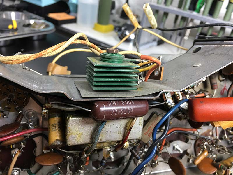
FIGURE 6. Selenium rectifier (green) prior to removal.
The Zener diode replicates the voltage drop in the selenium diode, thereby maintaining the original rectifier output voltage.
The power cord was stiff and the insulation was cracked where it entered the radio. I replaced the original non-polarized two-prong plug with a polarized two-prong plug (Figure 7).
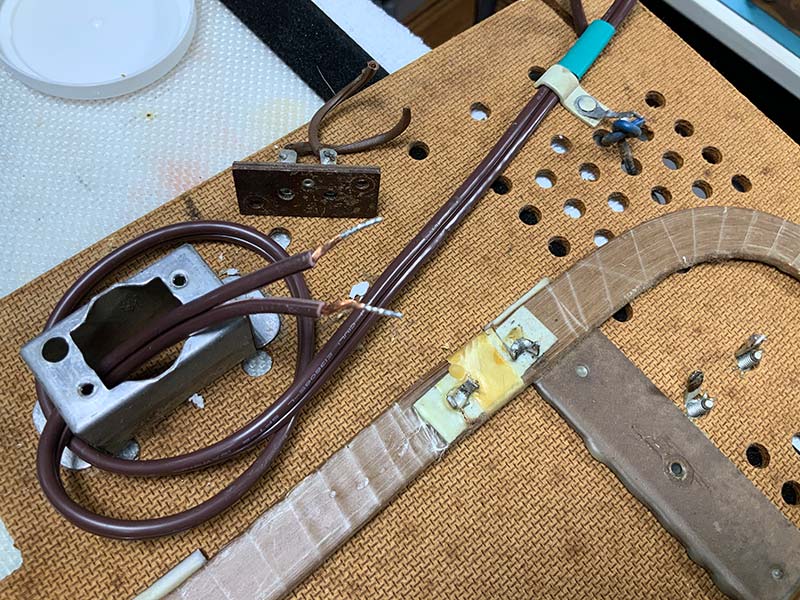
FIGURE 7. Connecting a new power cord to the two-prong connector in the radio.
Recapping
The next step is to replace wax paper and electrolytic capacitors with fresh, modern film and electrolytic capacitors of the same value and at least the original voltage rating. All wax paper and electrolytic capacitors will eventually fail. I’ve yet to find a wax paper capacitor from a ‘60s radio without significantly diminished capacitance and markedly increased leakage. As a result, a coupling capacitor between the plate of the tube driving a second tube will result in heavy plate current flow and early failure of the second tube — sometimes spectacularly. As such, I change every wax paper and electrolytic capacitor that I can get my hands on while I’m in the bowels of the radio. Figure 8 shows six capacitors that must be replaced.
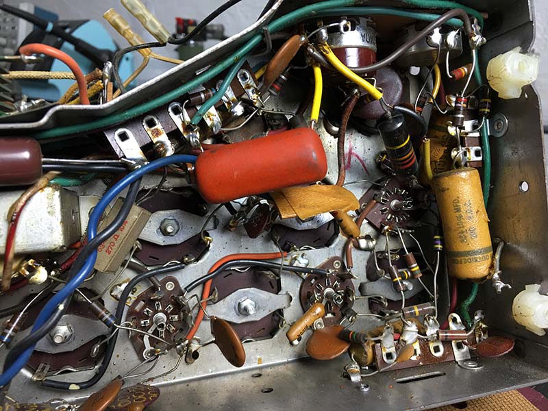
FIGURE 8. Original capacitors on the component side of the radio.
Modern film capacitors are compact, relatively affordable, and direct replacements for wax paper capacitors. I’ve had great success with the yellow metalized polypropylene film capacitors and the bright orange “Orange Dip” capacitors. Expect to pay between $0.30 and $1.30 for a film capacitor; less when purchased in a kit of standard value capacitors.
Electrolytic can capacitors dry out over time, as shown by the cross-section of the can electrolytic from my radio in Figure 9.
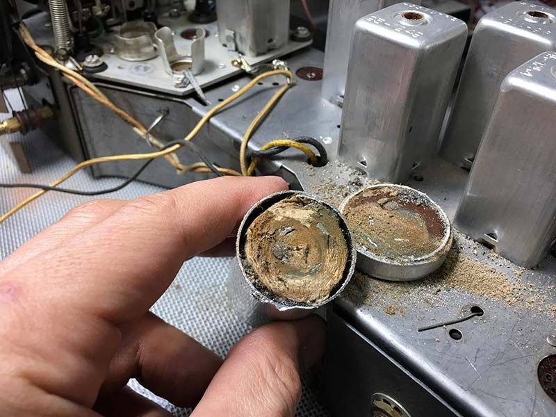
FIGURE 9. Cross section of a dry electrolytic capacitor.
Cans should be replaced with capacitors of equal capacitance and at least equivalent maximum DC voltage. My go-to for custom replacement electrolytic capacitors for any application is Hayseed Hamfest LLC (hayseedhamfest.com).
The electrolytic can capacitor for the Zenith (shown disassembled in Figure 10) is about $35.
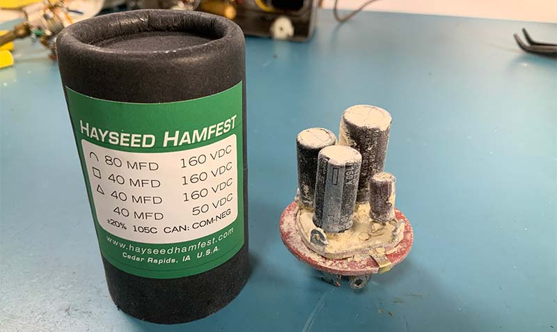
FIGURE 10. Inside a custom electrolytic can capacitor.
Cheaper but more time-consuming options include re-stuffing the original can yourself or bypassing the can altogether and installing discrete electrolytic capacitors on the underside of the chassis.
When replacing capacitors, try to maintain the position and orientation of the original capacitors, including the outer shell of film capacitors. This will minimize the introduction of noise and undesirable coupling between components. For example, the outer shell of a film capacitor is normally connected to ground or the low impedance side of a circuit to minimize hum and other noise.
Contact and Potentiometer Cleaning
Because of all the gunk, solder, and clippings of component leads flying around during recapping, save the cleaning of the rotary switches and potentiometers for last. I’ve had the best results by generously spraying contacts and pots with CRC QD cleaner and waiting 24 hours before repeating the treatment.
After the second application of cleaner, use a pointed cotton swab and fiberglass pen (Bergeon 6240) on the visible rotary switch contacts. Finish off the pots and switch contacts with a carefully controlled application of DeOxidizer spray. Try not to overspray the DeOxidizer because it leaves a tacky residue that attracts dust.
Learn to Read Capacitor Markings
Vintage capacitors — such as the bumblebee — have color codes to mark value and voltage ratings. Modern capacitors have standard markings that can be read directly, such as:
| Marking |
Value |
| 102K630V |
0.001 µF @ 630 VDC |
| 202K600V |
0.002 µF @ 600 VDC |
| 473K200V |
0.047 µF @ 200 VDC |
| 474K630V |
0.47 µF @ 630 VDC |
Resistance Check
Use an ohmmeter to verify that you haven’t made any changes in the circuitry that could cause a problem when power is applied. It takes only one clump of solder or loose screw to short circuit the high voltage to ground.
If you find anything unusual such as a low resistance from the plate of a tube to ground, then address it before moving on. It’s easier to make resistance checks with the tubes out of their sockets.
Using a tone generator, I found the tweeter was defective. I mounted the replacement (an inexpensive horn piezo tweeter from Amazon) using a large felt spacer next to the main speaker as shown in Figure 11.
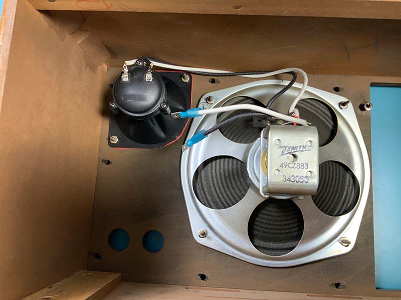
FIGURE 11. New horn tweeter connected in parallel with the main speaker.
Power-On
The next step is to slowly and carefully apply power, preferably using a variac, an isolation transformer, and dim bulb current limiter (you can see the setup back in Figure 1). The variac enables you to slowly increase the AC voltage to the radio, while the dim bulb limits the current to a few hundred milliamps or less.
The isolation transformer is mainly for your benefit because it removes ground reference should you accidentally touch the chassis when it’s hot. The first sign of life is typically the small lamps; in my case, two LEDs mounted in mini-bulb holders (see Figure 12).
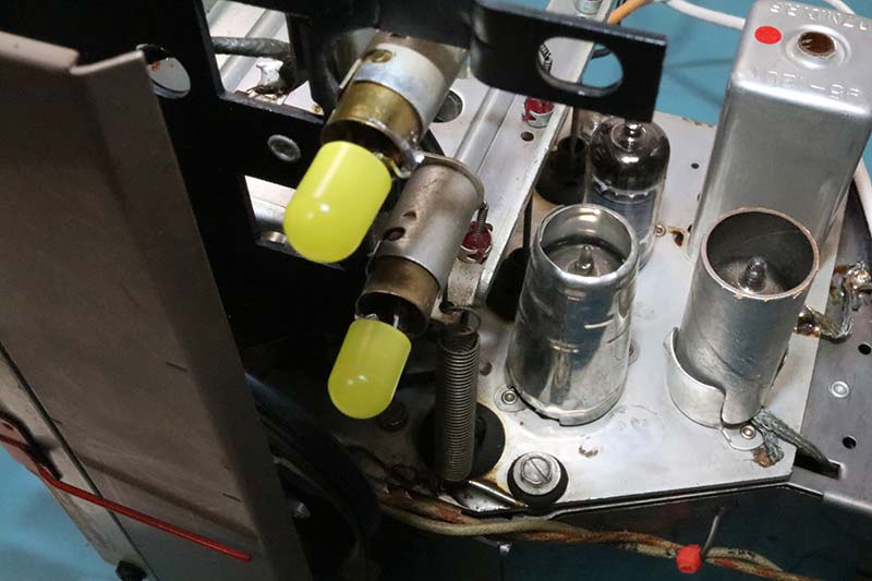
FIGURE 12. Homemade LEDs mounted in miniature bulb sockets.
After a 20 minute warm-up period, check the AM and FM functions separately. Are the signals strong and clean? Is there any hint of hum? How do the speakers sound? Problems in the sound circuit of the audio output could be related to a damaged speaker cone or other components. For example, a rushing sound could be due to silver migration in an old mica film capacitor.
ALIGNMENT
The next step is alignment of the AM and FM coils (Figure 13).
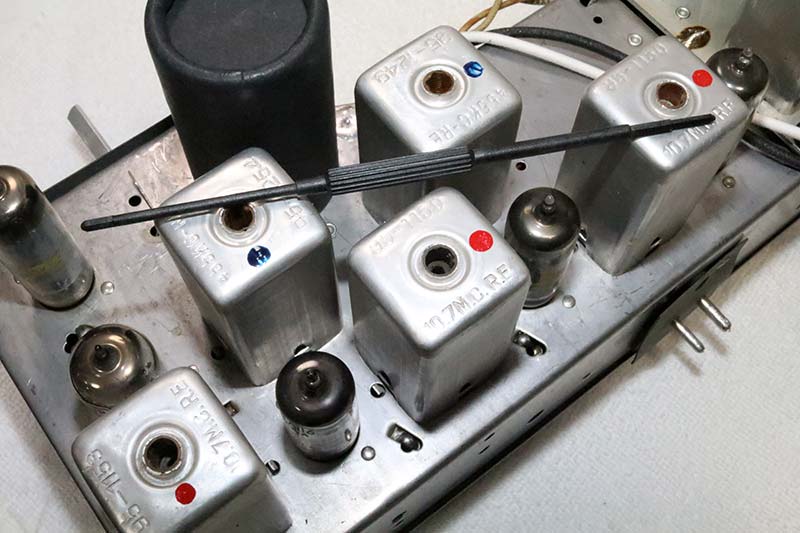
FIGURE 13. Alignment tool across AM (red) and FM (blue) transformers.
Following the instructions in the Sam’s documentation, tune the AM and FM segments for maximum audio output with a signal generator. For the AM section, this includes maximizing response of the IF circuit to a 455 kHz signal modulated at 400 Hz.
Alignment of the FM section includes maximizing response to a 10.7 MHz signal modulated at 400 Hz. Fortunately, the previous owner hadn’t fiddled with the transformers, and alignment took all of five minutes.
COSMETICS
I refinished the silver-toned knobs with Krylon ColorMaster spray in metallic silver. I used a Sharpie silver paint marker to repaint worn areas on the chrome trim around the main speaker.
A Q-tip with a little black enamel paint brought the raised text labels for the controls back to life.
The wood veneer cabinet needed a little work. Because the cabinet is a simple box without trim or ornamentation, it was an easy task to remove the original finish with an orbital sander and 300 grit sandpaper.
Two coats of Minwax sanding sealer followed by four coats of Minwax clear gloss lacquer, and the cabinets were as good as new.
END RESULT
The cost of restoration was 10 hours of labor and about $85, which included the cost of two tubes, a custom can capacitor, a little over a dozen film capacitors, a few power diodes, and a pair of LED bulb replacements. The details of the complete restoration of this radio could easily fill the pages of a book. My hope is that this article will give you an idea of the overall process and some vocabulary to work with as you scan the Web to prepare for your own renovation project.
At a minimum, you should learn more about dim bulb current limiters, autotransformers, and isolation transformers before plunging into your first vintage tube radio project.
Figure 14 shows the refurbished radio with the bulb current limiter to the side and variac autotransformer and isolation transformer to the rear of the unit.
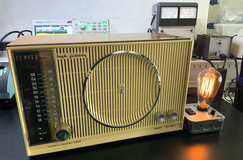
FIGURE 14. Refurbished radio on my workbench.
I’ll cover these and other technologies in more depth in future articles on vintage tube radios and equipment restorations. NV
Resources
Antique Electronic Supply (tubesandmore.com) - Handles just about everything, from metal can capacitors to schematics of vintage radios.
Hayseed Hamfest LLC (hayseedhamfest.com) - Custom replacement electrolytic can caps and kits for audio and ham electronics. The capacitor for the Zenith is about $35.
HiFiEngine.com - Manuals and schematics for vintage radios.
PartsConnexion.com - High-end film and electrolytic capacitors and resistors.
TubeDepot.com - My go-to source for vacuum tubes. The site has excellent comparisons on tubes from various manufacturers.