Recap
In our last episode, we looked at the LCD part of the LCD Navigator project. This time, we will look at the Navigator part: the five momentary pushbuttons arrayed as a cross in Figure 1.
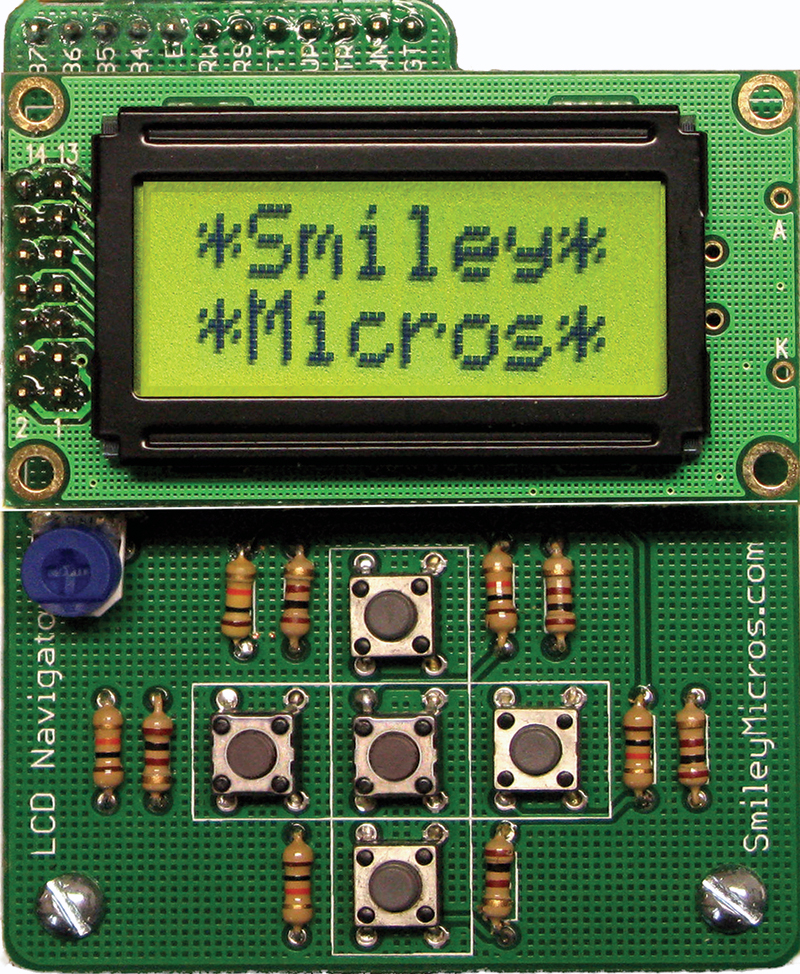
FIGURE 1. LCD Navigator.
These buttons can be used to navigate a menu much like you would typically do with a TV remote control five-button navigator as shown in Figure 2.
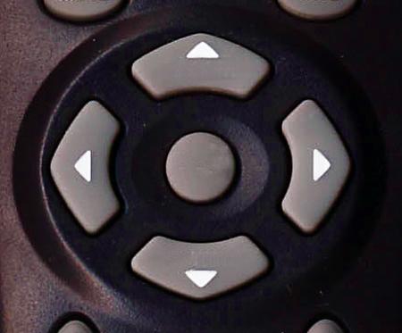
FIGURE 2. Typical remote control menu navigation buttons.
These buttons typically don’t have labels since most folks intuitively know that they are up, down, left, right, and select after just a few moments of messing with them and watching what happens on a TV menu.
We will first look at the hardware considerations for using mechanical switches like these pushbuttons. Then, we will learn to use the nav_button library that you can find in avrtoolbox, buried fairly deeply in the folder tree at avrtoolbox\libavr\source\driver\external_hardware\nav_button. You can get this from the avrtoolbox repository at https://github.com/nutsvolts/avrtoolbox. You will probably want to start with the tester library at avrtoolbox\libavr\testers\nav_buttons.
The LCD Navigator
The LCD Navigator board schematic from our last Workshop is shown in Figure 3; and a picture of it connected to an Arduino via a breadboard is shown in Figure 4. The breadboard wiring is shown in Figure 5. You may already have this wired up to test last episode’s LCD code.
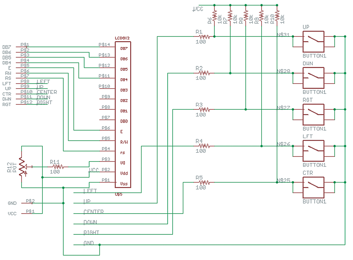
FIGURE 3. LCDNAV schematic.
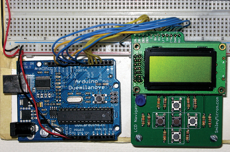
FIGURE 4. LCD Navigator with Arduino.
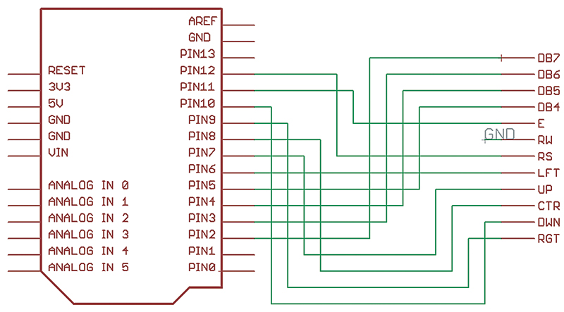
FIGURE 5. LCDNAV wired to Arduino.
LCDNAV wiring to the Arduino is as follows:
- DB7 Pin 2
- DB6 Pin 3
- DB5 Pin 4
- DB4 Pin 5
- E Pin 11
- RW GND
- RS Pin 12
- LFT Pin 6
- UP Pin 7
- CTR Pin 8
- DWN Pin 10
- RGT Pin 9
Navigator Buttons: Hardware
You can use this with the Arduino as shown in Figures 3, 4, and 5 or you can use the BreadboArduino that we used in Workshop 41 (December ‘11). [You can still get the BreadboArdino chaser lights project kit from the Nuts & Volts webstore.] Please keep in mind that even though we demonstrate the LCDNAV board using Arduino compatible hardware, we will use code that is regular C using the regular free AVR C tools: AVRStudio, WinAVR, and avrdude. (Please note that this was tested with AVRStudio 4.) To help wire this thing up, I’ve generated a label for the ATmega328p shown in both Figures 6 and 7 that you can print out and put on the chip using double-sided sticky tape. You can get this in avrtoolbox at /avrtoolbox/blob/master/libavr/testers/nav_buttons/ATmega328_label.doc.
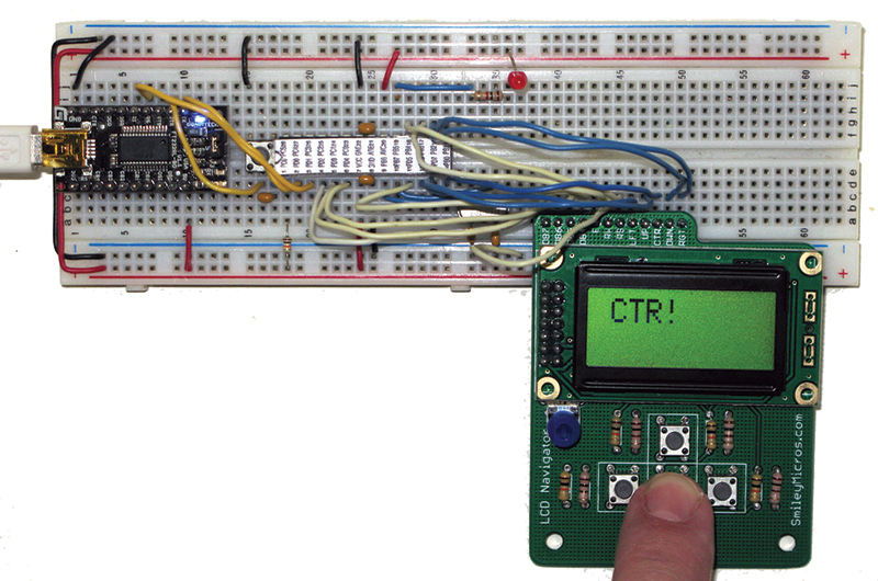
FIGURE 6. LCDNAV with the BreadboArduino.
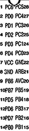
FIGURE 7. ATmega328 port pin label.
Wiring LCDNAV to the BreadboArduino
Now, get out the BreadboArduino chaser lights project that you did a few weeks back and pull off all those parts that were specific to the chaser lights. (Ouch! I know, but see the end of this Workshop for a PCB solution to your loss.) Figure 8 shows the BreadboArduino schematic and Figure 9 shows how you’ll wire up the LCDNAV connections to the ATmega328p on the breadboard. You saw how this should look in Figure 6. Good luck!

FIGURE 8. BreadboArduino basic wiring.
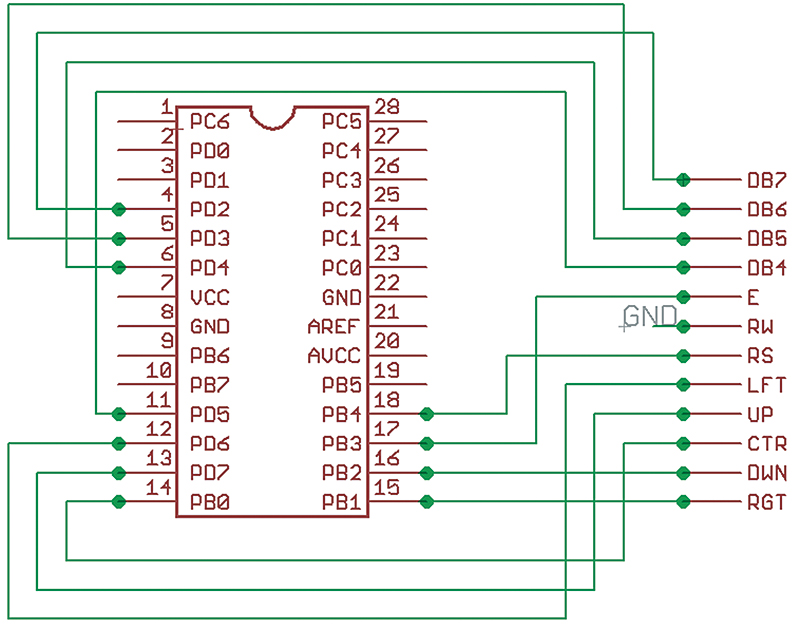
FIGURE 9. LCDNAV wired to BreadboArduino.
LCDNAV wiring to the ATmega328 on the BreadboArduino is as follows:
- DB7 Pin 4 (PD2)
- DB6 Pin 5 (PD3)
- DB5 Pin 6 (PD4)
- DB4 Pin 11 (PD5)
- E Pin 17 (PB3)
- RW GND
- RS Pin 18 (PB4)
- LFT Pin 12 (PD6)
- UP Pin 13 (PD7)
- CTR Pin 14 (PB0)
- DWN Pin 16 (PB2)
- RGT Pin 15 (PB1)
Navigator Buttons: Software
Whether you choose to build this project for an Arduino board or the BreadboArduino or any other AVR development board, you’ll want to first test it with the nav_buttons tester software. When you run this code, the first message output is “NavButt.” (I wasn’t trying to be funny; it’s just that with only eight characters and two lines we have to be parsimonious with our text.) This is followed shortly by the revision number, then the screen blanks and waits for you to press a button. Figure 6 shows the message that is printed if you press the center button: CTR!
The program spins in a forever loop - for(;;) checking the nav_available() function to see if — well, can you guess? Right. It returns 0 if no button has been pressed and not 0 if a button has been pressed. The ‘not 0’ is a number that has a bit for each button press identified. We assume that there will generally only be one bit set but you might get several pressed at the same time, so the code processes the bits sequentially setting each bit back to 0 when it has been handled until all the bits are set back to 0. As you will see shortly, this sequential processing gives you the opportunity to prioritize the key presses so that, for instance, the CTR key will always be processed before any other key.
The Navigator Library
The Navigator library consists of nav.c and nav.h which exposes a few simple functions:
void nav_init(); // initialize the navigator buttons<br />
uint8_t nav_available(); // true if a new button press is available<br />
uint8_t nav_get_button(); // return the next available button
LISTING 1
#include “c:\avrtoolbox\libavr\source\general\util\util.h”<br />
#include “c:\avrtoolbox\libavr\source\driver\external_hardware\<br />
lcd_hd44780\lcd.h”<br />
#include “c:\avrtoolbox\libavr\source\driver\external_hardware\<br />
nav_button\nav.h”
int main( void )<br />
{<br />
    uint8_t key = 0;
    lcd_init();<br />
    nav_init();
    lcd_puts(“NavButt”);<br />
    delay(500);<br />
    lcd_clear();<br />
    lcd_puts(“REV028”);<br />
    delay(1000);<br />
    lcd_clear();
  for(;;)<br />
  {<br />
    if(nav_available())<br />
    {<br />
        key = nav_get_key();
        if(key == CTR)<br />
        {<br />
            lcd_home();<br />
            lcd_blank(16);<br />
            lcd_puts(“CTR!”);<br />
        }<br />
        if(key == LFT)<br />
        {<br />
            lcd_home();<br />
            lcd_blank(16);<br />
            lcd_puts(“LFT!”);<br />
        }<br />
        if(key == RGT)<br />
        {<br />
            lcd_home();<br />
            lcd_blank(16);<br />
            lcd_puts(“RGT!”);<br />
        }<br />
        if(key == UP)<br />
        {<br />
            lcd_home();<br />
            lcd_blank(16);<br />
            lcd_puts(“UP!”);<br />
        }<br />
        if(key == DWN)<br />
        {<br />
            lcd_home();<br />
            lcd_blank(16);<br />
            lcd_puts(“DWN!”);<br />
        }<br />
        delay(100);<br />
        lcd_home();<br />
        lcd_blank(16);    <br />
    }<br />
  }<br />
}
Listing 1 makes for a very simple tester program. When we press the down button, the LCD shows DWN! as shown in Figure 10.
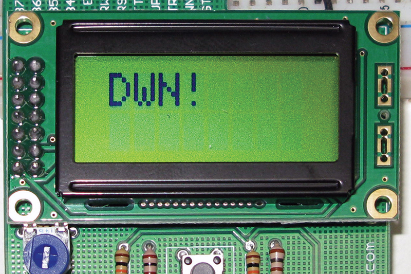
FIGURE 10. DWN!
As usual, this simplicity is hiding some complexity under the hood that we will look at in more detail. When you first look at this — especially if you are a novice — you might correctly ask ‘Where is all the code that notes when a button is pressed?’ Well, that is all set up by the nav_init() routine that sets up an ISR (Interrupt Service Routine) that runs in the background, out of sight of our main loop. A timer peripheral is set to interrupt the main code every 5 mS (milli-seconds or 0.005 seconds) and check the state of the buttons. If a button is low for five consecutive 5 mS intervals (25 mS), then we are reasonably sure that the button has been pressed. We will get into a lot of detail about timers and ISRs in another Workshop, but for now I recommend that you look at the nav_init() function to get a feel for what is going on.
There are several other neat tricks hidden under the hood of this code, including the way the port pins are mapped to each of the five buttons. For example:
#define NAV_LFT_PORTX PORTD<br />
#define NAV_LFT_DDR DDRD<br />
#define NAV_LFT_PINX PIND<br />
#define NAV_LFT_PIN PD6
Here we see that we require four separate definitions just for setting up the LFT button in the initiation. If you want to wire the buttons to different ports and pins, you will need to change them in these definitions in nav.h.
If you look a little deeper at the code in nav.c, you’ll see a rather bizarre-seeming algorithm for accepting a button push as valid. Before looking at that code, we’ll need to take a moment to examine the topic of switch bounce and the debouncing thereof.
Switch Bounce
Each of the Navigator buttons is connected to a 10K Ω pull-up resistor to VCC and a 100 Ω current-limiting resistor to the breadboard pin as shown in Figure 3. When the button is not pressed, the breadboard pin is pulled up to VCC and reads as a 1 if the associated AVR pin is set to digital input. When the button is pressed, the breadboard pin is connected to ground (through the current limiting 100 ohm resistor) and the AVR digital input reads 0. Well, this is going to be easy. We only have to look for a 0 or a 1, right? Wrong! In the button, the actual mechanical connection is not instantaneous and, in fact, the voltages bounce around and take a bit of time from a computer perspective to settle on either VCC or GND, which leads to the button being in output bouncing between 1 and 0 like crazy. Figure 11 illustrates what happens to the voltage across a switch as it is pressed and released.
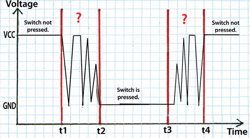
FIGURE 11. Switch bounce.
Jack Ganssle provides an excellent discussion of switch bounce at www.ganssle.com/debouncing.htm.
The algorithm I use in nav.c to deal with switch bounce is fairly clear and teachable, but not any where near the most efficient that can be used. As usual, I came up with what I thought was a good algorithm for dealing with this, only to find out on AVRFreaks.net (http://tinyurl.com/6hjz5yt) that others have been down this path before me and done a better job. I will admit that the ‘best’ way of doing this is very dense and not easy to understand, so for now let’s just use our less efficient technique and save the more efficient (and harder to understand) version for a later Workshop.
Some of the more perceptive readers will want to know why we have to use the 10K ohm resistor to pull up the switch when we can configure the pull-up resistors for the input pins. They may also want to know why we need the 100 ohm resistor at all. The answer is that this design is for novices using a breadboard and neither resistor would be needed if we could be sure that all users would use this thing properly. The 100 ohm resistor is there for the person who accidentally configures the button pin to output and then sets it high, thus providing a direct path from VCC to GND if the 100 ohm resistor wasn’t there to prevent it. The 10K ohm resistor is for the person who configures the pin to input and then sets it to 0, which would provide a direct path from VCC to GND.
Simple Menu Navigation Software
Unlike many of the software projects we encounter, menu software doesn’t lend itself to a generic library. Instead, it involves learning about and creating state machines that can vary in complexity from very complex to extremely complex. We’ll try to keep it as simple as we can and only use the C switch statement that we’ve seen before as our state machine in a simple demonstration application nav_menu.c that you can find under the avr_applications section of avrtoolbox. You can use it as a template if you want to write a menu system of your own. In this application, we will also show how to enter text and numbers using the Navigator keys.
The nav_menu.c application builds on the tester code shown above using a series of switch statements in functions to keep track of the system state. The program opens with the LCD showing the program name and revision as shown in Figure 12.
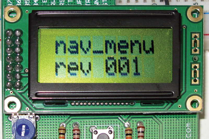
FIGURE 12. The nav_menu.
First, we define the number of states: #define MAX_TOP 5 — and don’t forget that since we are counting from 0, that the maximum of five means that we actually will have six functions named according to what they do as follows:
Enter text<br />
Enter number<br />
View text<br />
View number<br />
Erase text<br />
Erase number
When we run the code, the forever loop will either increment or decrement a variable ‘top,’ depending on our presses of the UP or DWN key:
if(key == UP)<br />
{<br />
    if (top <= MAX_TOP) top++;<br />
}
if(key == DWN)<br />
{<br />
    if (top > 0) top—;<br />
}
At the end of the loop, we wait half a second to make sure the user has pressed and released a key, then we show the ‘top’ number on the second line of the LCD:
delay(500);<br />
lcd_set_cursor( 0, 1 );<br />
lcd_puts(itoa(top,num,10) );
When the user pressed the center (CTR) button:
if(key == CTR)<br />
{<br />
    get_top(top);<br />
}
The get_top(top) function is called:
void get_top(uint8_t get)<br />
{<br />
    switch (get)<br />
    {<br />
        case 0:<br />
            entr_txt();<br />
            break;<br />
        case 1:<br />
            entr_num();<br />
            break;<br />
        case 2:<br />
            view_txt();<br />
            break;<br />
        case 3:<br />
            view_num();<br />
            break;<br />
        case 4:<br />
            erse_txt();<br />
            break;<br />
        case 5:<br />
            erse_num();<br />
            break;<br />
        default:<br />
            break;<br />
    }<br />
}
Suppose you press the up button four times to show the number 3, and then press CTR. This will switch to case 3 which calls the view_num() function:
//View number<br />
void view_num()<br />
{<br />
    lcd_clear();<br />
    lcd_puts_p(view_num_txt);<br />
}
The view_num_txt was defined as some text in PROGMEM space as follows:
const char view_num_txt[] PROGMEM = “view_num”;
The LCD displays the called function name on line one along with the number for that state on line two, as shown in Figure 13.
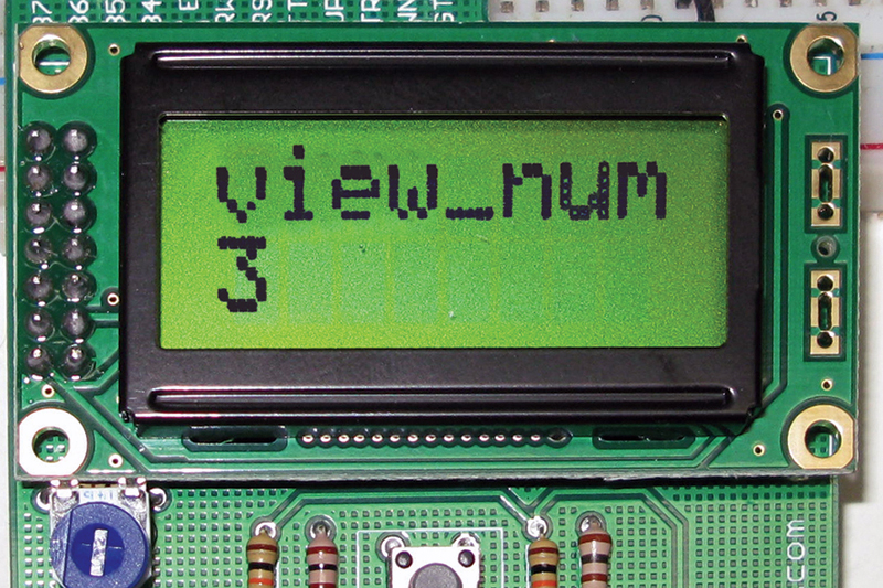
FIGURE 13. The view_num.
The functions that let you enter text and numbers are interesting, but a bit much for this Workshop so we’ll just let you look at the source code if you are interested.
Preview: Simple Chaser Lights Board
If you purchased the BreadboArduino kit and constructed the simple chaser lights project from our previous Workshop, you are probably going to think that it is such a shame to tear up that project just to get at the BreadboArduino so that we can test our LCDNAV. If only there was something we could do to have all those blinking lights AND test the LCDNAV board ... Well, Figure 14 shows that we now have an alternative to building the chaser lights on a breadboard; we can get a printed circuit board and parts kit from Nuts & Volts that lets you build a permanent platform for your chaser lights experiments.
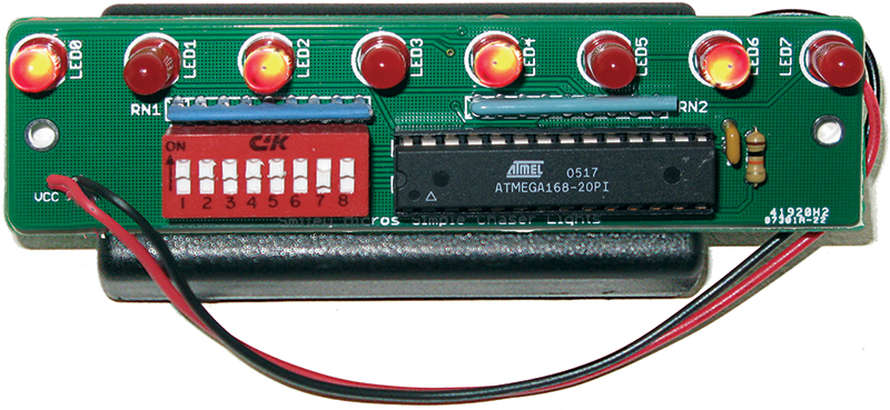
FIGURE 14. Chaser lights board.
The main difference between this board and the circuit discussed in Workshop 41 is that this one does not have a communication channel for reprogramming. It comes preprogrammed with most of the light patterns discussed before and, as a bonus, it has some POV (Point Of View) messages that allow you to write text in the air by waving the board like a wand as we’ll learn all about in our next Workshop. You will find the simple_chaser_lights and the pov_wand software in avrtoolbox under the avr_applications directory, so you can get a head start on this visually-arresting project before we look at the details next time. NV
Theory is all well and good, but to really learn this stuff you have to get your hands on some tangible items that blink, whirr, and sometimes detonate. As a service for the readers of the Smiley’s Workshop articles, we have simple and inexpensive projects kits available that can help you make it real. You can find these kits (and some darn good books) at the Nuts & Volts Webstore.