Microphones don’t generate a large output signal, millivolts at best. They almost always require a preamplifier of some sort to boost the signal to a useable level. Recently, I wanted to use an inexpensive electret microphone for a small short-range public address speaker and I needed to make an amplifier for it. Here’s what I did.
A Tested Approach to Design
I always follow a logical step-by-step process when I design something. Here’s the procedure as outlined in my own new book, Practical Electronic Design for Experimenters:
- State the design goal. Define the end-product. I always try to write it up in a design notebook I keep. Just jot down a couple sentences to describe what you want. You should have a notebook to record all your schematics, tests, doodles, notes, etc., on the project.
- List the key features and basic specifications. What are the inputs and outputs? My approach is to view the finished product as a black box with certain inputs and outputs. DC power and ground are usually a given. What else? Define them the best you can. Figure 1 shows what my black box looked like.
- Learn how the product or circuit works. Do an Internet search for operational details and some potential circuits. Also look in textbooks for the basic circuits to learn from. Be sure you know how the circuit works. Look for design procedures or ferret them out of the info you have. Draw a block diagram if you can.
- Select a circuit. Look at all your references and choose a circuit. You usually don’t design totally from scratch. If you find something similar to start with, then you modify and adapt it to your goal. Of course, you could just copy an existing circuit and build it. Invariably, most experimenters modify and enhance things they find and like.
- Do the design. Choose the components. Draw out a schematic to work from; one you can add to and modify.
- Simulate the circuit. If you have some simulation software like Multisim or an equivalent, create the circuit and simulate it. Tinker with the design until you get it to where you want it.
- Build a prototype. If you have no simulation software, go directly to a real circuit built on a solderless breadboard.
- Test the circuit to see that it does what you want. Modify and tweak until it’s working as you wish.
- Package. You may want to clean it up, make it smaller, and put it in a format for mounting in an enclosure. Perfboard is a good choice, so you don’t have to resort to the complexities of a printed circuit board.
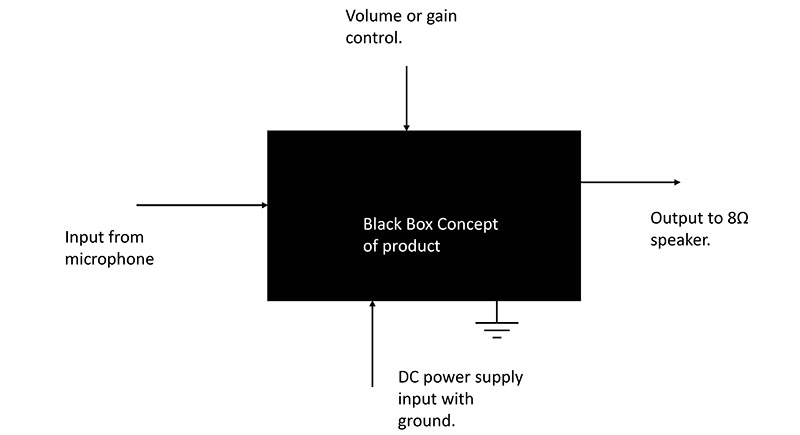
Figure 1: A 386 IC power amplifier that operates a three inch speaker.
Continuing the Design
Okay, here’s some notes to illustrate the process I went through.
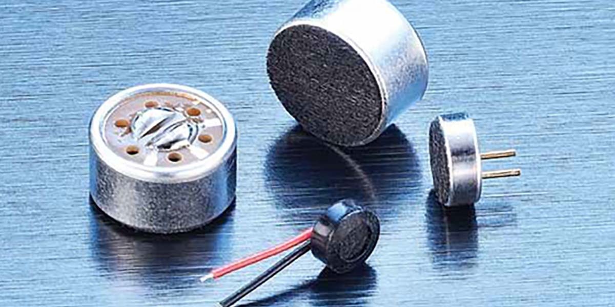
The first thing I did was to look at the specs for the microphone (mike). I got a datasheet to see what I needed to do. The electret I had was an inexpensive model that contains an internal JFET for some initial amplification and isolation. It can operate from a DC supply from five to 15 volts. Its frequency response is 12 Hz to 12 kHz. No output voltage was specified.
Next, I wrote down some amplifier specs as I saw and understood them:
- Gain needed, not known so test different levels (10, 100). Gain should be easy to change. The circuit probably should have a gain control. A simple pot voltage divider will do.
- Input source is an electret microphone.
- Input impedance, high, 1 MΩ would be nice.
- Output impedance, low is usually best. The desired load is an 8Ω speaker.
- Frequency response: 20 Hz to 12 kHz. This comes from the mike spec but I doubt that high fidelity is needed here.
- Power supply: 9V (chosen to fit a nine volt battery). Anything up to 12 volts should work fine also.
Next, an Internet search will turn up all kinds of circuits. Print out the details of those that interest you. Mark up any book references you find.
Select a circuit. My search turned up lots of electret microphone amps. They fell into these main categories:
- Bipolar junction transistor (BJT), discrete circuit
- JFET, discrete circuit
- Op-amp
Normally, I look for the circuit that is the simplest and requires the least parts. I prefer ICs over discrete component circuits. I tend to go right for the op-amp. However, the BJT and JFET circuits are really simple and cheap. Any of these will probably work okay. The BJT and FET design processes are very detailed and fussy. You need to choose a transistor, get the datasheet, then work your way through the biasing design, then the signal flow details.
The op-amp design is simpler and right out of the textbook. You should keep a good op-amp reference book on hand as so many projects can be implemented with op-amps. They’re simple and almost always work. It may be the single most useful IC available. Learn it and use it.
The key requirement here is that I need an amplifier that will drive a small speaker. That is a power amplifier. A general-purpose op-amp will not do it. So, I need a power op-amp. And such a thing does exist. One popular IC is the LM386. If you did a search on “power op-amp” this one probably came up. It will operate a small speaker and it’s configured as an op-amp.
I got the design info I needed from a few Internet searches, a datasheet, a textbook I had on hand, and my own new book. If you plan to do more design, you may want a copy of this as it contains most common circuits and design procedures. See the References at the end of the article for what I used.
Figure 2 show what I came up with. This LM386 IC power amp circuit is old, cheap, available, and still good. It can put out up to one watt under the right conditions and can drive a three inch speaker.
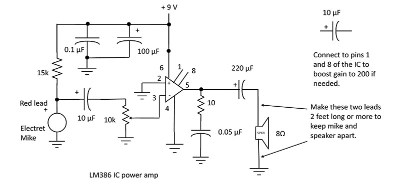
Figure 2.
This amp has a gain of 20 which should be enough to operate the speaker. Power supply voltage should be in the four to 12 volt range. The datasheet probably had this circuit in it. Not much heavy design work, but some design projects are just like that as the IC does all the work.
The question always comes up about where you get the specific component values. Many of them are guesses based upon prior experience. Some of them come from a recommended circuit in the datasheet. The 10K pot, the coupling capacitor to the speaker (220 µF), the 10Ω resistor, and 0.05 µF capacitor are right from the datasheet.
The 0.1 µF and 100 µF capacitors on the 9V line are decoupling/bypass capacitors that help keep the noise on the 9V DC line clean. I used a 9V power supply rather than a battery. It was noisy but the capacitors cleaned it up.
About the Microphone
I’ve worked with electret microphones before and, in general, had poor luck with them. They’re cheap and touchy. If you get a good one and set it up correctly, it will work. At 79 cents each, you get what you pay for. Of the three I purchased, only one worked. My suggestion is to test the mike before you hook it up to the amplifier.
Incidentally, the electret microphone is a polarized device. That means it should be connected with the correct polarity. If you have one of the microphones with leads attached, the black lead is negative and should be connected to ground. The red lead is positive and should be connected to the 15K pullup resistor to 9V. This is also your mike output. The unit I got had only two short unmarked bare leads that did plug neatly into the breadboarding socket.
One way to identify the leads is to use your ohmmeter as a continuity tester. Check to see which of the two pins is connected directly (OΩ) to the metal housing of the mike. That’s the negative lead that should go to ground.
You’ll need an oscilloscope to test the mike. That brings up one big issue with design. You aren’t going to be a good designer without a few good test instruments. Your digital multimeter (DMM) is one of them that you probably already have. You’re going to have to bite the bullet and get a scope. There are tons of choices including a used one, a cheap one, or one that is part of a virtual instrument that uses a PC or laptop as the processor and screen.
Just wire up the mike circuit as shown on the left in Figure 2. Connect +9V and ground. Connect the scope input to the output capacitor and ground. Then, while observing the scope, talk into the mike. Better still, shout.
Be sure the scope vertical amplifier is set to one of the most sensitive ranges like 20 or 50 mV per division. You should see some random voice signals displayed. I played around with the pull-up resistor and was able to maximize the output with the 15K value.
Yes, this is a crude test, but I discovered that I had two bad mikes after I built the whole circuit. It took some troubleshooting to figure this out. Test your mike first and eliminate that problem.
Incidentally, a good way to design is to build and test a circuit in stages, testing each individually before you hook them all together, Once you’re sure that the mike is putting out some voltage, build the amplifier and connect it to the mike.
Power the circuit and test to see if you can speak into the mike and hear it in the speaker. A word of warning: There will probably be lots of feedback between the speaker and mike causing oscillation and screeching or a steady tone. Keep the speaker and mike as separate as possible. The recommendation note in Figure 2 says use long wires on the speaker to keep it away from mike. This circuit did amplify my voice, but it was not loud.
If you really need more gain, you should connect a 10 µF capacitor between pins 1 and 8 on the 386 IC; again, refer to Figure 2. This bumps the gain up to 200 — a huge gain. If it’s too loud, remember, you do have a 10K gain control to set the output to an acceptable level.
The ultimate test is to turn all the circuits on and speak into the mike. The speaker output should be loud and clear. Be careful of feedback from speaker to mike. Otherwise, all you will get is loud tone as the whole thing goes into oscillation. NV
References
If you're going to do more design, you need a basic reference library. The books below are a good place to start. Check on the publisher website, Amazon, or your other favorite sources.
- Carter, B. & Mancini, R., Op-Amps for Everyone, 3rd edition, Newnes/Elsevier, 2009.
- Frenzel, L., Practical Electronic Design for Experimenters, McGraw Hill, 2020.
- Horowitz, P., and Hill, W., The Art of Electronics, 3rd edition, Cambridge University Press, 2015.