In our last episode, we finished up our extended series on Arduino/Fritzing prototyping to production. You should now be able to create excellent documentation for your designs that includes images for your breadboards, schematics, and layouts for printed circuit boards (PCBs). These skills will come in very handy as you proceed into the world of Arduino-based systems development and beyond. This time, we are going to start a two-part series on an Arduino-based handheld prototyper shown in Figure 1.
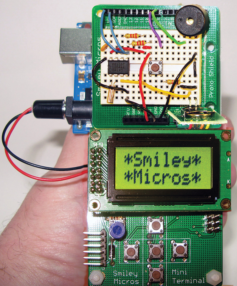
FIGURE 1. Arduino handheld prototyper.
We will have Fritzing components for this system (Figure 2), so we can continue using our excellent Fritzing breadboard and schematic images to document our work as before.
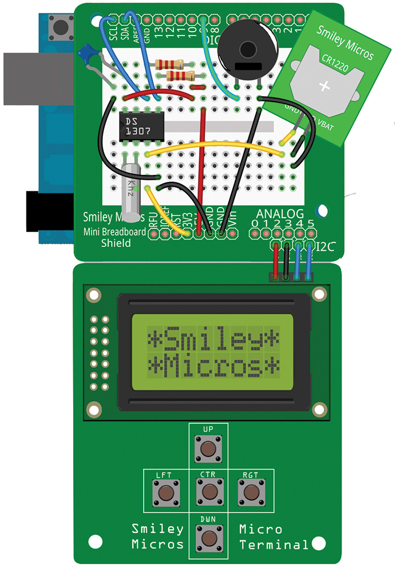
FIGURE 2. Arduino handheld protoyper in Fritzing.
The Arduino handheld prototyper — as the name implies — let's you develop prototypes that are portable in your very own hand, plus provides a bonus that is lacking in the stand-alone Arduino: It can accept user keypad input via pushbuttons and provides the user with visual output via an LCD.
Excelsior!
In case you’re wondering, the title to this section means either 'still higher' or 'fine curled wood shavings used to pack fragile items.' My use is in the 'still higher' sense of things, meaning we've just finished a steep climb developing our prototyping skills with Fritzing and the Arduino proto shield. Now, we are going still higher.
Think of this as mountain climbing. You've just arrived at the top of the foothills next to the base of the mountain. You've got a long way to go, but you've put in quite an effort to get this far. Time to stop and look around, to gaze off in the distance, and rest a bit before the next climb. I've been climbing a long time, and one thing I've noticed is that each time I reach a peak, I look up and see a higher peak. The learning never ends, but that is a big part of its attraction. Excelsior indeed!
For our next climb, we are going to learn to use the handheld prototyping system we’ll be discussing here so that we can continue our Arduino development without having to be tethered to a PC all the time. We’ll take all the stuff we've recently learned and combine it with what we covered about the LCD Navigator way back in Workshops 42 and 43.
The Arduino Handheld Prototyper
Our exercises so far have almost all been tethered to a PC via a USB cable. That is really great for learning because you have a robust power supply built in, and you have immediate access to all the great development and debugging tools available on a PC. Microcontroller designs are often used away from a PC, and are embedded deeply into other systems (for example, controlling the sensors and actuators in an automobile engine) or are carried around by the user as handheld instruments like a multimeter. In fact, being away from big computers is one of the main reasons that folks use microcontrollers. Generally, at some point, for an embedded system to be really embedded, it must get away from a PC. So, we need a way to develop for non-PC-tethered applications.
The Arduino handheld prototyper is made from three separate subsystems. You may recognize the upper part from Figures 1 and 2 as the Arduino proto shield we've been using for the past few articles. The lower PCB looks a lot like that LCD Navigator mentioned above — but it isn't. This one has brains.
The LCD Navigator had a parallel interface and required a microcontroller to run it. However, the I2C mini terminal has a built-in microcontroller (ATmega328P) that operates the LCD, reads the pushbuttons, and communicates via the I2C bus.
Introducing The Serial Mini Terminal
The LCD Navigator is great for prototyping LCDs and buttons on a breadboard, but it uses up too many of the Arduino pins to be practical for a handheld device. The I2C mini terminal only uses the two I2C lines from the Arduino, leaving all the rest of the I/O pins available for prototyping on the proto shield.
I took the LCD Navigator design and ported it to our Fritzingduino concept (meaning that I added a minimal Arduino clone to it). Figure 3 shows the I2C mini terminal with the LCD removed.
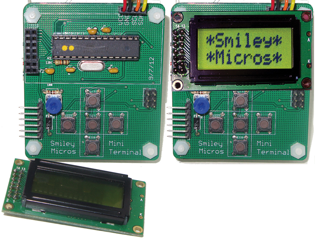
FIGURE 3. I2C mini terminal with the LCD removed.
You can see that under the LCD is a circuit that looks an awful lot like the Fritzingduino. It has an ATmega328P with an Arduino-compatible bootloader, along with associated crystal, reset, and communication circuitry. You can communicate with the ATmega328P using the FTDI connector as discussed for the Fritzingduino, and/or you can program it with the ISP header.
It is a fully functional (minimal) Arduino clone; it has a bootloader and can communicate with a PC, and it is pre-loaded with the I2C mini terminal application so that it can function as a terminal server for the Arduino under the proto shield. In its intended use, you'll never have to utilize the bootloader and change the application. However, if you get a clever idea that you want to test with this board using it as an Arduino clone but with user input and output, there is nothing to stop you! Hack away and be sure and tell me if you make it better. [Note that the IC in Figure 3 has two yellow dots on it. These aren't eyes; they are a marking that indicates this ATmega328P has an Arduino-compatible bootloader, the mini terminal software, and that it has been tested.]
This design concept means that you are actually using two Arduino-compliant ATmega328P microcontrollers in one handheld: the ATmega328P on the mini terminal and the ATmega328P on the 'real' Arduino under the proto shield. The mini terminal ATtmega328P behaves as an I2C slave to the proto shield I2C master, puts characters on the LCD when told to do so, and returns the status of the buttons when instructed. We'll look in detail at the slave software in our next Workshop.
The really great thing about using I2C on the Arduino is that it has a novice-friendly library built into the Arduino IDE, so you can develop handheld systems that use the LCD and the buttons without having to understand anything about I2C. You use it as a simple black box and leave the details to the experts.
The Base
To make this development tool 'handheld,' I've designed a plastic base shown in Figures 4 and 5 that you can bolt the Arduino proto shield and mini terminal to. It even has a cutout so that you can stick a nine volt battery to the back of the mini terminal with Velcro™ and be able to change the battery easily. The base is laser-cut from clear plastic and is sort of invisible in a photograph, so for Figures 4 and 5, I Photoshopped a blue tone so that you can see it better. The whole thing is held together with nylon nuts and bolts, making it easy to assemble and disassemble.
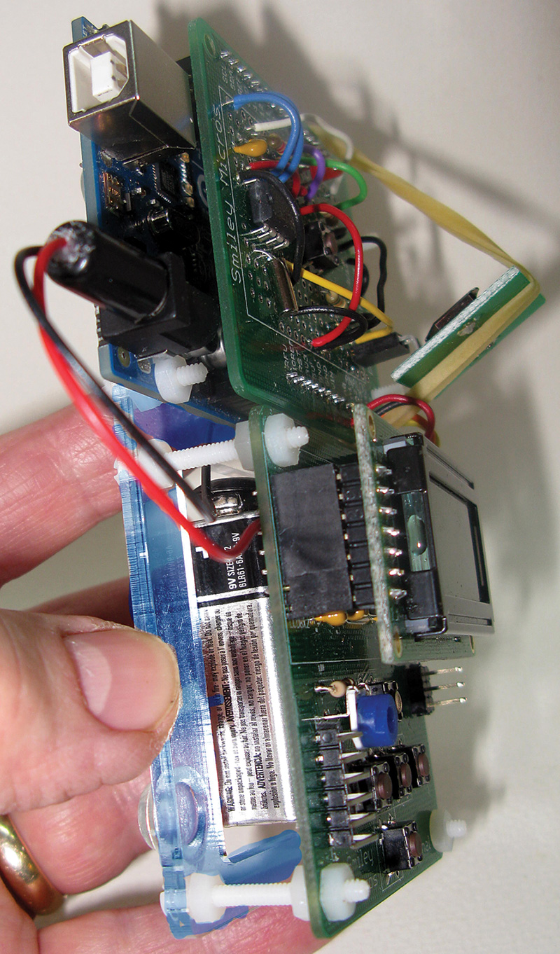
FIGURE 4. Side view showing the base with a slight blue tone.
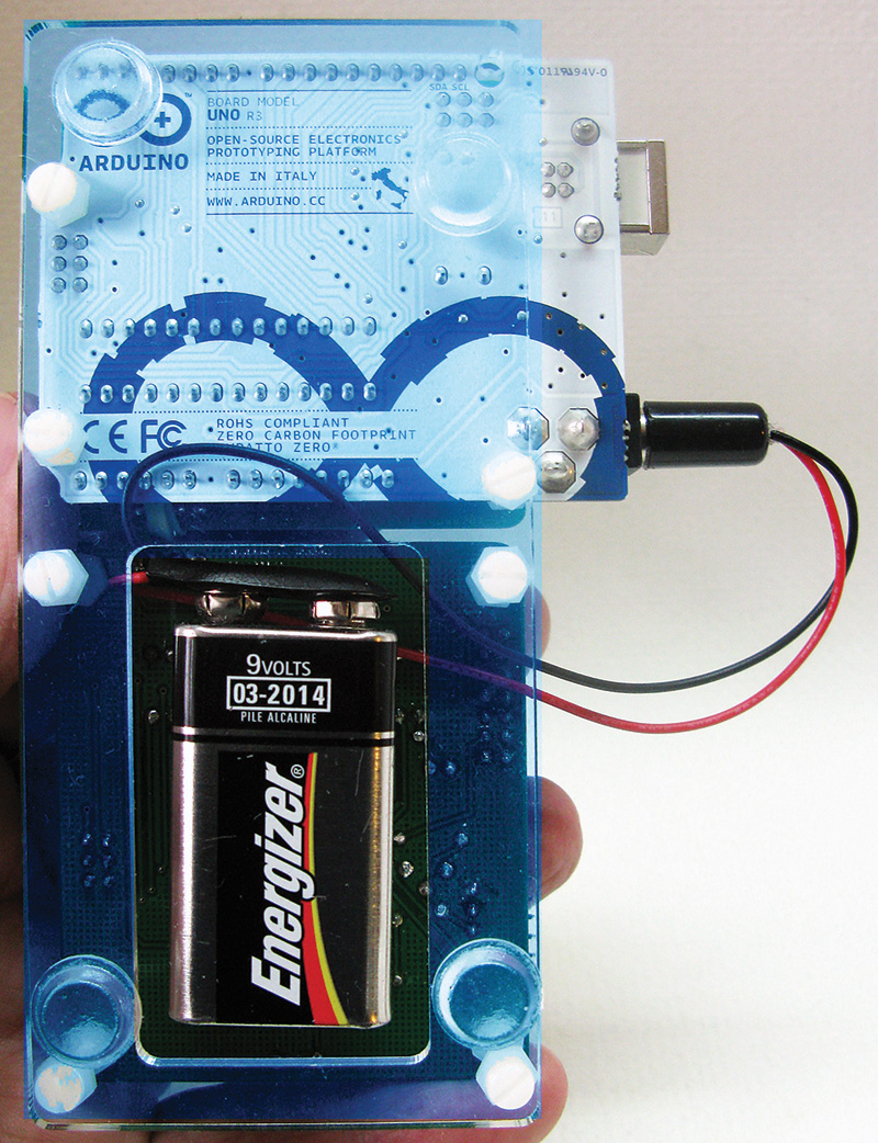
FIGURE 5. Back view.
I would expect a user of this system to develop a somewhat Frankenstein looking handheld tool that works great even though it looks like crap [note the rubberband I neglected to hide in Figure 4]. Then, once it is perfected, you can put on some makeup and lipstick. Actually, the point is that after you get it all working, then you can decide how you need to package your creation so that Elsa Lanchester won't run off screaming when you put you project on Kickstarter. [That metaphor should win an award].
Building The Serial Mini Terminal
Rather than spend a lot of time and space here showing step-by-step how to build the I2C mini terminal, I'll just say that if you DIY, you'll need that ATmega328P to have an Arduino-compatible bootloader on it. [In case you’re interested, there is an I2C mini terminal kit available from the Nuts & Volts webstore.]
In our last Workshop, I discussed how to put a bootloader on an ATmega328P using an Arduino as an ISP programmer. What I didn't mention is that everybody seems to call the ATmega328P the ATmega328, as I did. Well, they are wrong just like I was.
There is an ATmega328 and an ATmega328P, and they are different beasts. It is not just that the 'P' model uses less power, it also has a different signature. So, when you try to use the ArduinoISP program which calls avrdude, the signature gets checked and it won't like it if the signature doesn't match. Even the Arduino documentation for the ArduinoISP software just calls the chip an ATmega328 — IT IS WRONG!
I know this because I have both chips and I could only get the ArduinoISP to work with an ATmega328P. You can get it to use the ATmega328, but you've got to jump through so many hoops that is just isn't worth it IMHO. Stick with the ATmega328P and save some time and trouble.
How To Use The Arduino Handheld Prototyper
Let's look at a little program that has the Arduino in the proto shield read a button on the mini terminal and then tell the LCD display on the terminal to show the name of the button. This not only demonstrates the basic functions of the mini terminal, it shows how easy it is to use it. Easy is good. First, however, a word or two that might help prevent confusion.
We are going to use two sets of code. One set is resident on the I2C mini terminal and operates the LCD and the pushbuttons — this is the slave code. The other set of code runs on the Arduino and is the master code. A lot of the master code puts stuff on the LCD, but it does this by telling the slave code to do it. It does the same for reading the pushbuttons.
You will need to install the mini terminal library in your Arduino IDE. You can get this library and testing software in a single file called MiniTerminal.zip in the article downloads. Unzip this file and then copy the MiniTerminal folder to the libraries section of your Arduino installation. In my case, this was C:\Arduino-1.0.4\libraries\Mini Terminal.
To use this library, you open your Arduino IDE and (as shown in Figure 6), open the Sketch menu and select Import Library…\MiniTerminal.
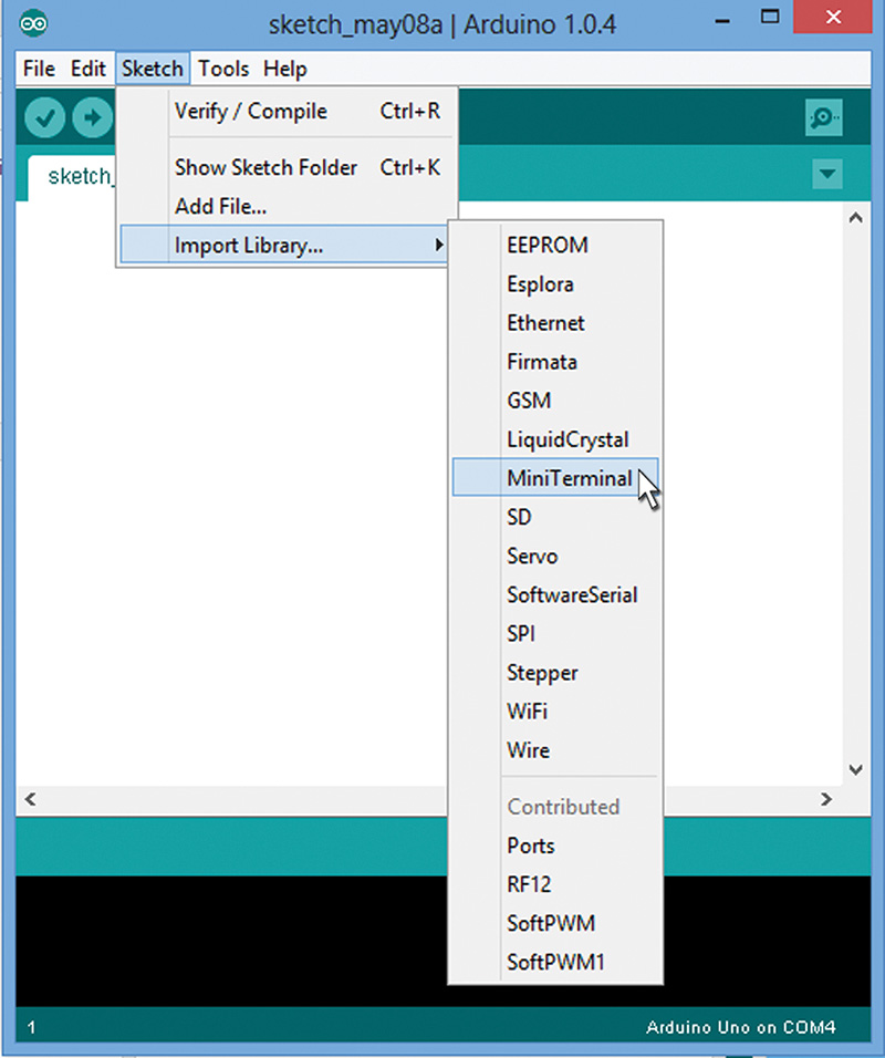
FIGURE 6. Import library.
This will write to the top of the program the #include <MiniTerminal.h> required to use the library as shown in Figure 7.
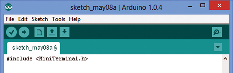
FIGURE 7. Library imported.
The following mini_terminal_master software runs on the Arduino:
// mini_terminal_master Joe Pardue 5/9/13
#include <MiniTerminal.h><br />
#include <Wire.h>
// Store strings in program memory<br />
p_string(Hello) = "Hello";<br />
p_string(world) = "world!";<br />
p_string(up) = "up";<br />
p_string(down) = "down";<br />
p_string(center) = "center";<br />
p_string(left) = "left";<br />
p_string(right) = "right";<br />
p_string(error) = "error";
int oldMillis = 0; // used in checking for<br />
button presses<br />
byte last_button = 0;
void setup() // one time functions to get<br />
started<br />
{<br />
  Wire.begin(); // join i2c bus (address<br />
  optional for master)<br />
   <br />
  mt_home(); // Tell the LCD to put the cursor<br />
  an the upper left<br />
  mt_clear(); // Clear the LCD<br />
  mt_print(Hello,0,0); // Print Hello on line 1<br />
  mt_print(world,0,1); // Print world! on line 2<br />
}
void loop() // repeat functions forever<br />
{<br />
  // use millis() to check for available buttons<br />
  // about 10 times a second<br />
  if( (millis() - oldMillis) > 100)<br />
  {<br />
    last_button = mt_get_button();<br />
    oldMillis = millis();<br />
  }<br />
 <br />
  // see if a new button has been pressed<br />
  if(last_button){<br />
    show_button();<br />
    last_button = 0;<br />
  }<br />
}<br />
// Send the last button requested back to<br />
// the LCD to display<br />
void show_button()<br />
{<br />
  mt_clear();<br />
 <br />
  if(last_button == LFT)<br />
  {<br />
    mt_print(left,0,0);  <br />
  }<br />
  if(last_button == UP)<br />
  {<br />
    mt_print(up,0,0);<br />
  }  <br />
  if(last_button == CTR)<br />
  {<br />
    mt_print(center,0,0);    <br />
  }<br />
  if(last_button == RGT)<br />
  {<br />
    mt_print(right,0,0);<br />
  }<br />
  if(last_button == DWN)<br />
  {<br />
    mt_print(down,0,0);   <br />
  }<br />
  if(last_button == 0)<br />
  {<br />
    mt_print(error,0,0);   <br />
  }   <br />
}
Save Some SRAM
The first thing you may notice is the section beginning:
// Store strings in program memory<br />
p_string(Hello) = "Hello";<br />
…
This uses a macro p_string located in the MiniTerminal.h header file that lets us store strings of data in program memory. In microcontrollers, SRAM that is used to run the program tends to be precious and small, while the program memory tends to be stored in a cheaper and larger type of memory such as data Flash in the AVR. However, the C (and C++) compilers gcc and g++ (used by the Arduino) will put character strings in SRAM.
The version of these compilers used by the Arduino has some special features that allow you to store and retrieve strings in the cheaper program memory, but these features are somewhat arcane and frankly, a bit much to throw at typical Arduino users. I won't burden you at this time by showing you the macro or the functions that use the strings; you can look at it in the header file if you are curious.
It might seem like a bit of overkill to go to all that trouble since (in this example) we are only using a few short words, but in a real world application you might want to present a lot of information to the user. So, it is good to have an option that won't run you out of memory.
Press Some Buttons
To run the mini terminal from an Arduino, you need to connect the +5, GND, and the two I2C lines SCL and SDA on to the Arduino proto shield as shown in Figure 8. (You can also hook these wires directly to the Arduino if you don't have the shield. Just make sure you get the SCL and SDA wires to the correct socket position.)
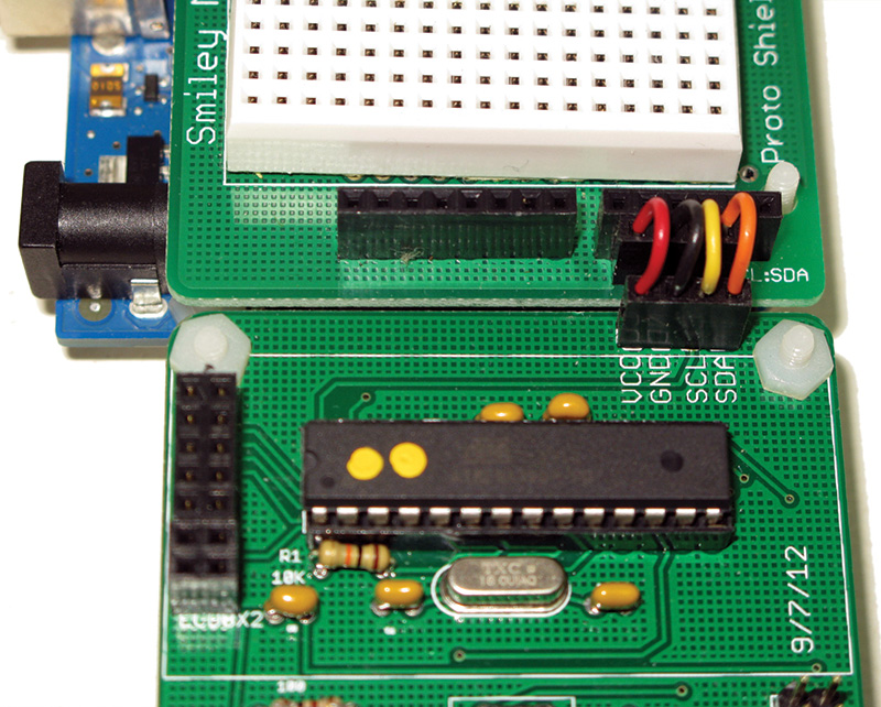
FIGURE 8. Wire the I2C and power.
Next, you load the mini_terminal_master program shown above into the Arduino. You should see the 'Hello world!' message shown in Figure 9.
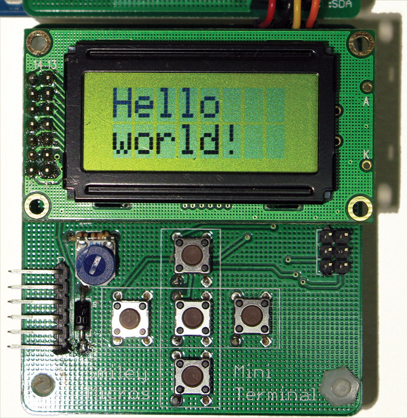
FIGURE 9. Say Hello World!
Now, start pressing the buttons. The button presses are read by the Arduino and then the name of the button pressed is sent back to the LCD as shown in Figure 10.
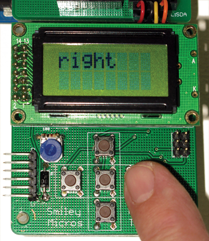
FIGURE 10. Press right.
When you use this later for a real world application, the up, down, left, and right buttons will be used to scroll around in menus. We will use the center button shown in Figure 11 to select a menu item.
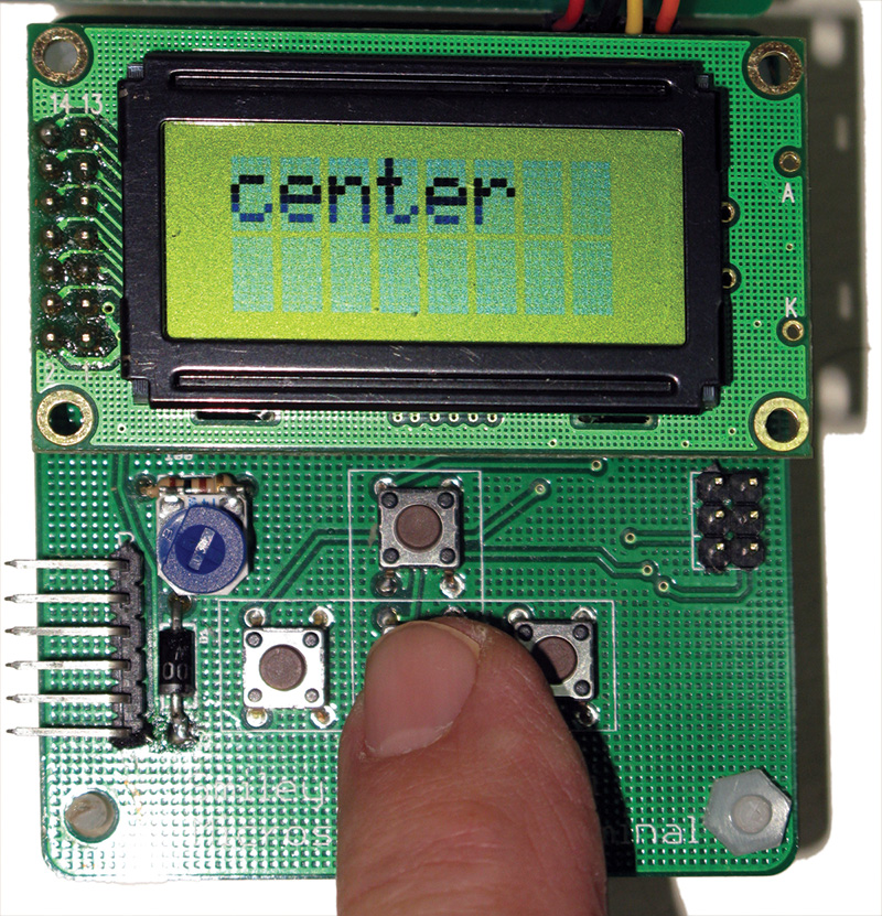
FIGURE 11. Press center.
You are probably already familiar with the paradigm since it is pretty much what all TV remote controls do with their similarly arranged five pushbutton keypad. Of course, they generally have a lot more keys for things like selecting the number of a channel, but as you'll see in our next installment, you can do a lot with these simple keys including inputting numbers without having special number keys.
Well, that should get you started. Next time, we'll look a little deeper at the master software and then look at the slave code. We will then apply the Arduino handheld prototyper to a practical project that helps heat and cool a castle by controlling the fresh airflow based on reading indoor and outdoor temperature and humidity.
Did I say castle? Well, if you consider a large stone construction with a timbered Great Room, suits of armor, and broadswords a castle, then yes we are going to learn how one person uses our prototyper to help heat and cool his castle. (This is a perfect application for our new tool!) See you next time! NV
Downloads
What’s in the zip?
mini_terminal_master.ino
Other source code files