Radar and Electronic Warfare (EW) are usually thought of as being very complicated and very secret. And while this is true for specific designs and detailed theory, many of the basic principles are straightforward and easy to understand. This article will present some of the fundamental concepts of radar and show how EW develops from that.

As most folks know, radar (RAdio Detection And Ranging) came of age in World War II. And everybody knows that radar sends out a radio signal that bounces back from an object. The range (distance away) of that object is determined by timing how long it takes for the echo (return signal) to come back. Most everyone has seen huge parabolic antennas rotating in circles, scanning the sky for incoming airplanes or missiles. At the least on TV and the old sci-fi movies. Many radar systems use such antennas. But some don’t.
It’s also important to remember that the antenna performs two functions. It acts as a transmitting antenna for the out-going pulse and as a receiving antenna for the return signal. This means that the transmitter must be disconnected (or turned off) during the time you want to listen for a return signal. Otherwise, any return signal will be overwhelmed by the transmitting pulse. Additionally, precautions must be made so that the receiver front end isn’t damaged or destroyed by the powerful transmitting pulse.
Let’s examine the basic radar geometry and design factors. Signal strength is a critical factor in the performance of any radar system. Obviously, if you can’t detect the return signal, you can’t detect the object. The more powerful your transmitter is, the greater the potential range of the radar. The larger the transmit/receive antenna, the greater the range. The larger the target (called Radar Cross Section or RCS) the stronger the return signal and the greater the range. While not obvious, the longer the wavelength, the less signal loss there is. So lower frequencies are better. (However, lower frequencies mean larger and heavier antennas.)
Of all these factors, the range (distance to target) is the most critical factor. This is pretty obvious when you think about it. A transmitter’s signal decreases by the square of the distance. Twice the distance means one-quarter signal strength. But the return signal decreases by the square of the return distance, as well. So, the return signal decreases in strength to the fourth power of the distance. So, doubling the distance to the target results in 1/16 of the signal being returned (all else being equal).
It’s for this reason that radar transmitters are immensely powerful. They can transmit very short pulses (about 50 µS) that are tens of megawatts and more. For example, the AWACS (Airborne Warning And Control System) klystron-type transmitting tubes are rated at 50 megawatts peak pulse power. Since the pulses are short and the repetition rate (or pulse rate) is about 1,000 pulses per second, the average power is much less — about 250 to 500 kilowatts. But that’s still plenty powerful. Of course, not all radars are this powerful. Some portable or weapons radars are only a few watts.
In order to locate an object, both its range and direction need to be determined. The range is obviously determined by the delay of the return signal. The direction is determined by where the antenna is pointing. If this seems rather crude, you’re right. Directional sensors measure the elevation angle and the azimuth angle (compass heading).
Naturally, the radar antenna must be properly aligned and calibrated so that its elevation and azimuth angles agree with the real world (or with the ship’s bow or missile’s flight direction). The angle sensors are often “synchros” or “resolvers” which are a special type of transformer and will not be discussed further.
Acquisition and Targeting Radar
There are two general classes of radars: acquisition and targeting. The acquisition radars are the big, stationary, long-range kind while the targeting radars are usually smaller, portable, and shorter range (sometimes being the guidance system of a weapon). They have two different functions.
Acquisition radar is used to detect objects from a long distance away. Since the object is a long way off (sometimes thousands of miles), its position, relative to the radar, can’t change all that much in a few seconds. For that reason, acquisition radar only illuminates (or “paints” or “lights up”) an object once every revolution of the antenna (which is typically every few seconds or so).
For reference, a airplane moving at 700 mph, or the speed of sound at sea level, only travels about 1,000 feet per second. A 2,000 or 4,000 foot difference at 100 miles is not too significant. Acquisition radars are the typical types shown in the movies and were the types used in WWII.
Targeting radars are used to guide weapons to a target. Sometimes these are ground-based radars and sometimes these are incorporated into the weapon itself. A “guided” missile is one that is directed by ground-based radar to a target. A “homing” missile directs itself from the radar reflection.
Note that a homing missile can use a ground-based radar to illuminate the target. And in the early days of radar this was very useful because it meant the missile didn’t need a radar transmitter. However, if the illumination signal was lost for whatever reason, the missile would “lose track” (or “lose lock”) and fail to hit the target.
Additionally, it meant that a ground radar was dedicated to that target for the duration of the missile’s flight. That’s not a problem if there are only a few slow airplanes coming at you. But with today’s vast numbers of fast fighters/bombers, this approach is not used too much.
The fundamental difference between acquisition radar and targeting radar is the idea of “radar lock.” Acquisition radar loses lock and re-acquires (re-detects) the object during every revolution of the antenna. Targeting radar must never lose radar lock because it has no real means of finding the target to begin with.
A targeting radar is always initially directed to a target by some outside means. This could be by linking it with an acquisition radar system, which is typical for ground-based missiles. Or, it could be by actually pointing the missile at the target and allowing the missile-radar to lock on, which is typical for air-launched missiles. Since it is imperative for a targeting radar to maintain lock, it must send out radar pulses at a much higher repetition rate, often at 100’s or 1,000’s of pulses per second. It can’t allow the target to move too far between pulses or radar lock could be lost. And at close range, there can be considerable relative-position changes at high-speeds. Therefore, high pulse rates are the key indication that a targeting radar is in use.
Radar System Signatures
Since radar systems are expensive to design and develop, there are a limited number of systems in use around the world today (perhaps a few hundred). Clearly, it is important to know what particular radar system you want to defeat before you can design a particular defense or countermeasure.
There are a handful of characteristics that identify a given radar system. The first is the frequency of operation. The second is the pulse length. The third is the pulse repetition rate. The fourth is the scanning rate or the time it takes for the antenna to rotate 360 degrees. The fifth is the antenna radiation pattern which is broken down into the “main lobe” and “side lobes.” These side lobes turn out to be a very significant weak point in any radar system and can be used to create confusion and misrepresent the target.
 |
|
FIGURE 1. A typical polar plot of a radar antenna sensitivity pattern. Note that the side lobes are only 10 dB to 15 dB below the main lobe.
|
A radar “beam” is not just one beam. It’s really a number of beams. Figure 1 shows a typical radar antenna pattern. There is one main beam (or main lobe or focal point). This is where the antenna is actually pointing and has the most power during transmitting and the most sensitivity while receiving. But no antenna is perfect. There are actually a number of secondary beams called side lobes. These are identified in Figure 1. Typically, the two major side lobes have a reduced sensitivity of only 10 dB to 15 dB relative to the main lobe. We’ll see how this can be employed for EW in more detail, later.
Basic Radar Countermeasures
There are two radar countermeasures than have been used for some time: chaff and jamming. Chaff started in WWII and consisted of airplanes dropping aluminum-foil strips — called chaff — to create multiple reflective targets and to block radar beams from penetrating (like a smoke screen). Chaff is effective for both of these functions if the length of the aluminum-foil strips is appropriate for the radar frequency that is being used. If the length of the foil is too different from the radar wavelength, it loses its effectiveness. (This is why it is important to know the radar signature before attempting countermeasures.)
Jamming is another method of defeating radar. It consists of transmitting continuous signals directly at the radar antenna that are the same frequency of the radar. Since a transmitter can be much more powerful than a radar reflection, it will present the receiver with a large signal and the weaker return signal will be masked. This significantly reduces the effective range of the radar. Eventually, the target will get close enough to the radar system so that the radar return signal will be larger than the jamming signal. When this occurs (called burn through), normal radar operation can be resumed.
Note that powerful jamming transmitters can be located so far away to be virtually untouchable. Also, due to the side lobes of the antenna, the jammer can affect multiple sectors (angles) of the radar. The radar display shows “spokes” of interference that are related to the side lobe pattern. Therefore, there are several directions that can hide incoming targets. Multiple jamming transmitters, it different locations, can create additional interference/spokes and reduce the effectiveness of radar to a significant degree.
ARMs and False Targets
An Anti-Radiation Missile (ARM) is arguably an EW component. It’s actually a missile that is designed to lock on to a radar signal (or “radiation”), home on it, and destroy the antenna and anything close by. It’s a fairly simple idea that is somewhat harder to put into practice. This is because there are many different radar signatures that the missile must be programmed for. You obviously wouldn’t want one to target your own radar signal.
ARM missiles put the radar operator in a dilemma. If they use the radar to search for targets, they expose themselves. (Literally, it’s like a search-light at night.) If they turn off the radar, they are no longer exposed but they are also ineffective. Neither choice is appealing.
False targets can be created several ways. The simplest is a form of jamming. Instead of transmitting a continuous signal, pulses that match the radar signature are transmitted. So instead of spokes on the display, there are many dots that look like targets. Trying to find a real target among hundreds of false ones is not a trivial matter.
A more sophisticated method of false target generation uses the Achilles heel of radar or the side lobes. As noted before, the side lobes are often only 10 dB to 15 dB below the main lobe in sensitivity. So, if you transmit a “return pulse” that matches the radar’s signature while the side lobe is pointing at you, the radar will think it is a main-lobe reflection. The result is that the antenna is pointing in the wrong direction and any weapon than is controlled by that radar will be
aiming at a false target.
 |
|
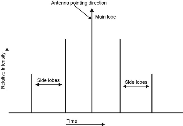
FIGURE 2. A stationary receiver detects a series of signals as the radar antenna rotates. The amplitude of the signals is related to the main lobe and side-lobe pattern, as shown in Figure 1.
|
Let’s examine this in more detail. As you approach a radar, you will be able to obtain its signature before it detects you. (This is because the return signal must travel all the way back to the radar.) Your radar receiver will detect pulses of different strength as the acquisition radar antenna rotates. Figure 2 shows a typical pattern with typical side lobes. Since you know the RCS of your craft, you can estimate when the radar will detect your return signal. Before that time, you (your computer actually) create a return signal of your own. Figure 3 shows such a constructed return signal.
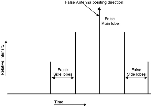 |
| FIGURE 3. Knowing what the radar signature is from Figure 2, a false return signal can be created. |
Then you transmit this false return signal at just the proper time in the radar signature so that the largest return signal appears on a radar side lobe. The radar system assumes that the largest return signal occurs in the main lobe. But in this case, it isn’t. The radar antenna is actually pointing in a significantly different direction from you. The error can be as much as 30 degrees. So, if this acquisition radar directs a weapon at you, it’s really pointing in the wrong direction. (Figure 4 shows how this happens.)
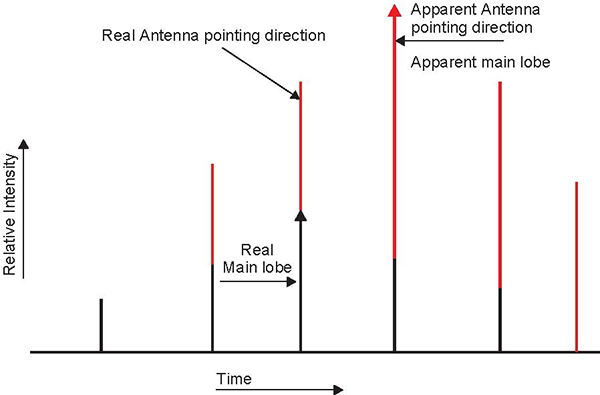 |
| FIGURE 4. Combining the false signal with the real signal creates a false signal that appears real to the radar. The radar antenna is pointing in the wrong direction when the largest return signal is received. |
If that weapon has a targeting radar, it is very likely that it will never achieve lock-on because you will be out of its field-of-view. With proper timing, these false return signals can be made to “move” at any speed or direction (within limits). Multiple false targets with multiple headings can be generated with a single side lobe transmitter. Such an approach can be used, to a degree, with targeting radars, as well. But it is harder because of the higher pulse rates and because targeting radars don’t re-acquire the target and expose their side lobes as much.
Other Topics
This article barely scratches the surface of this topic. There is much, much more. Phased-array and doppler radars have their own strengths and weaknesses. Stealth design and some tactical maneuvers can cause problems for radars.
The field of EW is usually broken down into ECM (Electronic Counter Measures) and ECCM (Electronic Counter-Counter Measures). The basic approaches described here fall into the ECM category. There are methods for reducing the effectiveness of jamming, chaff, and false targets. These methods are ECCM.
EW is like a chess game. Every move by one side is answered by the other side. The competition will continue until the day that humans have thought up every possible method of ECM and ECCM. That day appears to be in the far future. NV