Ever wish you could build an “audio telescope” that would let you hear things that were faint or far away? Well, this article shows you how to build such a thing. We call it the Big Ear.
The Big Ear is shown in Figure 1. Its most obvious feature is its parabolic dish reflector.
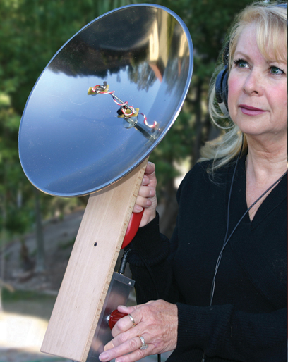
FIGURE 1.
The reflector concentrates sound energy onto a microphone that connects to a very high gain amplifier (see sidebar on parabolic reflectors). And believe it or not, it’s all assembled on a wood base you can find in a place that sells concrete supplies and tools! More about the wood base later; first we’ll discuss the amplifier.
The amplifier is built on a printed circuit board (PCB) and mounted on stand-offs inside a small aluminum box along with a nine-volt battery. Jacks for the microphone and headphones — along with an on-off switch and a volume control — are mounted on the box. Input jack J1 accepts a 2.5 mm mono plug that is wired to an electret microphone. Output jack J2 is for a 3.5 mm stereo plug that is standard on many headphones.
Circuit Description
Figure 2 is the amplifier schematic. Voltage to power the microphone comes from the five-volt zener diode D3. Resistor R11 limits the current in D3. The five volts are applied through resistor R1 which sets the bias current for the mic and the gain of the FET amplifier built into the mic. Also, R1 and C2 form a low-pass filter to remove any high frequency electromagnetic interference (EMI) that might come in via the microphone wires.

FIGURE 2.
The microphone is capacitively coupled via C1 to inverting amplifier IC1. Because of C1, DC gain of IC1 is 1 while the AC gain is set by the ratio R5/(R2 + R1). C4 across R5 limits the bandwidth of IC1. With a wide-band amplifier like the TL071, you should limit the bandwidth to limit the noise (see sidebar on op-amp noise). For op-amp IC1, the inputs need to be referenced to a level that is between the positive and negative voltage “rails.” Since the circuit is powered by a single 9V battery, R3 and R4 create a signal ground for the plus-input of IC1. C3 is a bypass cap to connect AC signal ground to DC ground.
Since the mic will pick up loud sounds as well as faint ones, we need to limit the output of IC1. That job is done by R6 together with diodes D1 and D2. D1 and D2 are wired in parallel with opposite polarity to allow current to flow both ways. Normally, the output of IC1 is a lot less than the 600 mV or so needed to put a diode into conduction. So, the diode pair acts like an open circuit and R6 is isolated. A loud sound drives the output of IC1 high enough to turn on the diodes placing R6 in parallel with R5. That lowers the gain of IC1 from 5 down to about 0.1. D1, D2, and R6 form a limiter. Originally, I was going to use an automatic gain control (AGC) circuit, but it got too complicated. To keep things simple, I opted for a limiter. You can use an oscilloscope to see the output of IC1 at test-point TP.
Output of IC1 is coupled through C5 to the volume control (R7). R7 has an audio taper instead of a linear taper. With a linear pot, the ohms per degree of rotation is constant. As a voltage divider, 20 degrees rotation gives twice the voltage of 10 degrees rotation. For most applications, that’s what you want. But the way our hearing works, loudness increases with the logarithm of the sound power. An audio taper pot varies the resistance so that the change in loudness per degree of rotation is constant.
The wiper of R7 goes to the input of power amplifier IC2. Unlike IC1, IC2 has a built-in resistor network to establish signal ground for its inputs. C6 is a bypass cap for that internal bias network. Note that IC2 is used in non-inverting mode. Since IC2 is a power amp, it can draw relatively large current “slugs” from the battery which could cause small fluctuations in the nine-volt supply. Such fluctuations could be picked up at the input of IC1 causing an accidental feedback loop. If IC1 and IC2 were both inverting (or both non-inverting), it would be positive feedback and the whole circuit could oscillate. If one amplifier is inverting and one is non-inverting, it’s negative feedback which is stable. There are other possible feedback paths through the supply. That’s why we use C11 across the battery and C10 from power to ground at IC2.
Figure 3 shows the schematic of the LM386 used for IC2.
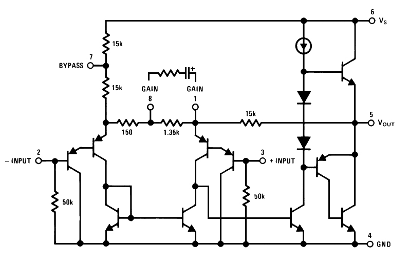
FIGURE 3.
For stability, the LM386 needs a 10Ω load at high frequencies, which is supplied by R9. C8 allows IC2 to “see” R9 only at higher frequencies. With pins 1 and 8 open, IC2 has a fixed gain of 20. To increase AC gain, a resistor (R8) in series with a capacitor (C7) is placed between pins 1 and 8. The AC gain is given by the formula:
AV = 30K / REQ
where REQ = 150 + (R8 * 1.35K)/ (R8 + 1.35K). In this circuit, R8 is a jumper wire to get the maximum gain of 200. The DC gain stays at 20. The output of IC2 is coupled via C9 to the headphones jack J2. The 10Ω resistor in series with C9 does two things. First, it makes the output of IC2 look more like a current source for low impedance headphones. That can improve the sound quality. Second, it prevents IC2 from seeing a shorted output.
Hiss Filter
The total gain of the amplifier circuit is approximately 5 x 200 = 1,000. Even though IC1 is a relatively low noise op-amp, with that much gain you will hear some random noise in the form of a hiss. To lessen the hiss, you can install Rx and Cx to lower the gain of IC2 at higher audio frequencies. On the other hand, if you need to hear those frequencies (for, say, bird-watching), you can just leave Rx and Cx out. Or, you could mount another toggle switch on the aluminum enclosure and switch Rx in or out as needed. Rx shunts the internal 15K feedback resistor of the LM386. The LM386 is stable only for gains greater than 9, so if Rx is too small, IC2 could oscillate; the datasheet suggests a minimum of 2K ohms.
The Circuit Board
Parts are mounted on the PCB as shown in Figure 4.
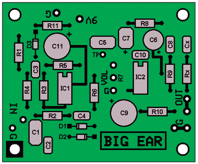
FIGURE 4.
Figure 5 shows the assembled board. Note the three-wire connector between the volume control and the board. Since R7 is an audio taper pot, it must be connected so that turning its shaft clockwise increases the volume. The wires connecting the input jack to the amplifier should be twisted and kept away from other components.
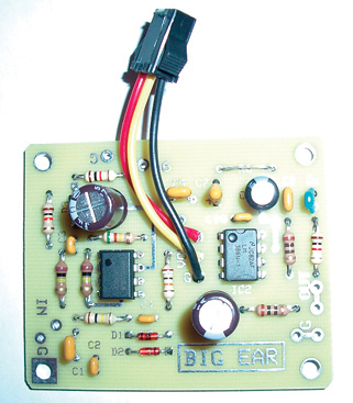
FIGURE 5.
Mounting the Amplifier in the Aluminum Box
Figure 6 is a photo of the aluminum enclosure. It’s RadioShack part number 270-238, with dimensions of 5.25 x 3.0 x 2.13 inches.
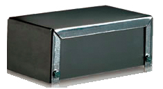
FIGURE 6.
In Figure 7, the enclosure is opened up to show the mounting of the amplifier PCB and battery holder along with the jacks, switch, and volume control.
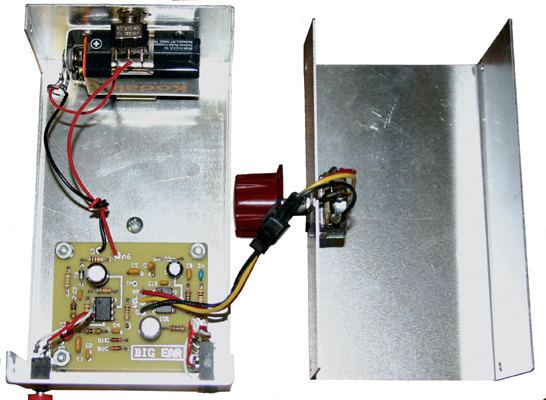
FIGURE 7.
The amplifier is mounted on four male-female 4-40 by 1/4 inch aluminum standoffs. One way to locate the screw holes for the standoffs is to use the blank PCB as a template. Position the board where it will be mounted and — while holding it firmly in place — mark the hole locations by inserting the tip of a pencil into each hole and tracing its circumference. Lift off the board and press a sharp metal point into the center of each of the four circles you just drew. Then, drill the holes with an 1/8” drill bit. You’ll also need to drill holes for the jacks, the volume control, the on/off switch, and the battery holder. For the jacks, find a drill bit that is slightly larger than the threaded part that goes through the sheet metal. If you use a pot with any anti-rotation tab, first drill the main hole for the pot. Then, insert the pot and rotate it so that the tab scribes a circle around the mounting hole. Drill the tab hole at some point on that scribed circle.
The metal battery holder is mounted to the box using four 2-56 pan head screws. I used small screws to avoid having the screw heads cut into the battery. Before inserting a battery, double-check the wiring from the battery holder to the PCB. You really don’t want to apply reverse polarity to those chips.
Testing the Amplifier
Before applying power, clean the board with rubbing alcohol and an old toothbrush, and give it a careful visual inspection. Look for the usual suspects:
- Bad solder joints
- Broken copper traces
- Shorted copper traces (especially IC pads)
- Reversed polarity on capacitors
- Wrong value capacitor
- Diodes in backwards
- ICs in backwards
- Wrong IC in a socket (if you used sockets)
- IC (or socket) lead bent under and not in hole
- Missing components (especially monolithic caps)
Once you’re sure there are no obvious problems, measure the resistance from +V to ground. If it’s low or zero, there’s a problem. If you used sockets, pull the chips out one at a time. If the short goes away, you’ve located the problem area. Otherwise, look for shorted traces.
Test the amplifier before mounting the box to the wood base. Insert a 9V battery and button up the enclosure. You’ll need a 20 inch length of twisted-pair stranded wire. Each wire should have a different color. Jameco sells a 100 foot roll of BLK/WHT 24/2 wire as their part number 173164. You can also take two lengths of wire and twist them yourself. (I’ve seen people use a low speed hand-drill to do the twisting.) Attach the 2.5 mm plug to one end of the cable, and remember which color is signal (the tip) and which color is ground. Then, solder the electret mic to the other end. (Remember, electret mics are polarized; solder the ground wire to the pin that connects to the metal case of the mic.)
Plug in the headphones, plug in the mic, turn the amplifier on, and listen. Verify that the volume control works. If it all works, turn it off and unplug the mic and headphones. Unsolder the mic and proceed to mount the amplifier box to the wood base.
Mounting the Enclosure to the Wood Base
Figure 8 is a photo of the wood base. It’s a tool called a “float” and is used to smooth out freshly poured concrete. It’s 15 inches long by 3.5 inches wide by 0.4 inches thick. It’s model 8029 sold by Lowes under the TASK FORCE brand as number 024530 (for under $5). The handle is offset, so the aluminum enclosure fits nicely on the long end while the reflector mounts to the short end. The reflector has been attached in this photo.

FIGURE 8.
Before you can mount the enclosure to the float, drill four holes in the wood to clear the heads of the 4-40 screws that hold the board standoffs to the box. That way, the enclosure will fit flush to the wood as the screw heads fit into the holes. The holes don’t have to go all the way through; 1/4 inch deep should do. Use a drill bit that is slightly wider than the screw head. Before drilling, hold the box against the base and push so that the four screw heads mark the wood. That tells you where to drill.
To attach the box to the base, hold the box flush to the wood and drill an 1/8 inch through the middle of the aluminum and through the wood. Then, put a wood screw through the hole and tighten it to hold the box to the wood.
Mounting the Reflector to the Wood Base
The reflector used is an Edmund Scientific model 3053875. It has a 12 inch diameter, a three inch focal length, and a 0.75 inch center hole for mounting. To mount the dish to the base, drill a clearance hole for a 10-32 screw through the short end of the base. Use a carpenter’s square and a pencil to draw a line across the base just above the handle as shown in Figure 8. Then, draw two diagonal lines as shown. Where the diagonals cross is a point on the center line of the base. Use the carpenter’s square to draw the center line through the point.
Position the reflector along the center line and mark the spot where you will drill the mounting hole. Before mounting the dish to the base, we need to drill a 1/4 inch hole through the side of the dish for the microphone wires to pass through. Locate the hole close to the bottom of the dish, but not so close that it’s blocked by the wood base. Insert a rubber grommet in the hole.
Figure 9 is a detailed drawing of the mounting hardware. (It is not to scale.) To keep it simple, lock washers are not shown. Note the 1/4 inch flat washer inside the mounting hole of the dish. Its outer diameter is about 0.74 inches; its purpose is to help center the mounting screw. The fender washers are 3/16 x 1 inch. The one under the coupling nut is used to hold the dish to the base. A 3/4 inch 10-32 socket head screw is used. You need to get the screw very tight, and a hex key allows much more torque than a screwdriver. The coupling nut has a 3/4 inch height and a 5/16 hex size.
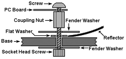
FIGURE 9.
Figure 9 is just one way to do it. You may have a better way to mount the reflector to the base. If you use a different reflector than the one used here, you’ll have to figure out a way to mount it.
Mounting the Microphone
For the reflector to work properly, the microphone must be mounted as close to the focal point as possible. The Big Ear uses two small PCBs and a length of threaded rod as shown in Figure 10 (again, not drawn to scale).
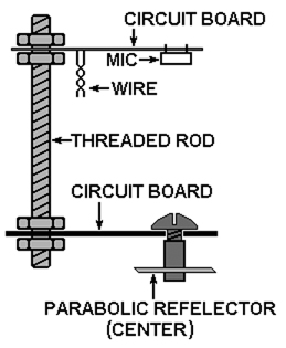
FIGURE 10.
The bottom PCB is mounted on the coupling nut at the bottom of the dish. The mic is soldered to the top board and faces towards the bottom. The top PCB has a clearance hole so it can be moved along the threaded rod and be locked in place by two nuts and lock washers. Insert the twisted-pair wire through the grommet and wrap it loosely around the threaded rod a few times. Cut off any excess length and solder the wires to the top board. The square pad should be the mic ground, but verify that it is (see Figure 11).

FIGURE 11.
Figure 11 shows the PCBs used to mount the microphone. Figure 11(A) is the bottom board while 11(B) and 11(C) show both sides of the top board. The mic is mounted on the side with the word MIC on it. The mic is placed so that it lies over the strip of copper near the mounting holes. In Figure 11(A), note that the two holes are different sizes. The larger hole is for a 10-32 screw that holds the board to the coupling nut at the center of the reflector. The smaller hole is for 6-32 threaded rod. Since the parabolic dish we used has a three inch focal distance, we used a three inch 6-32 screw instead of threaded rod.
Adjusting Microphone Position
If you know the focal length of your dish, then use a ruler to position the mic at the focal point. If you don’t know the focal length, there are two empirical ways to find it.
If your dish is shiny and reflects light, expose it to a bright light and use a piece of paper to find the focal point. Move the paper towards the bottom of the dish and find the point where the spot of light on the paper reaches its smallest diameter. That’s the focal point. (If you use sun light, be careful not to burn a hole in the paper.)
If you can’t use light, use sound. You’ll need something that generates a steady audio tone at a frequency around 1 kHz. Point the dish towards the sound and adjust the position of the mic while you listen to the output of the amplifier. The sound will be loudest at the focal point.
Headphones
Inexpensive headphones usually have ear pieces that sit on the ears letting some sound leak out. You can get feedback if the mic picks up the leaked sound. Better headphones have ear pieces that fit over the ears and don’t leak sound. However, better headphones often use a 1/4 inch plug. You can get a 1/4 inch to 1/8 inch adapter at RadioShack (part number 274-875). Since 3.5 mm is slightly larger than 1/8 inch, the adapter will fit. Or, if you plan to use only those headphones, you can replace the 3.5 mm jack with a 1/4 inch jack.
Wrap-up
Well, that’s about it. Go out and discover all the neat sounds you’ve been missing with your new Big Ear. NV
Parabolic Reflectors
Parabolic reflectors are everywhere, from radio telescopes to dish antennas for satellite TV to the reflector in a flashlight. Figure PR-1 is a photo of a parabolic reflector.
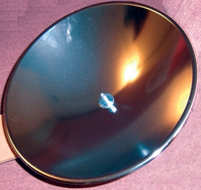
FIGURE PR-1.
Parabolic reflectors like the one in figure PR-1 are based on the properties of a parabola, one of those conic sections you may remember from high school math. Figure PR-2 is the graph of a parabola showing y as a function of x.
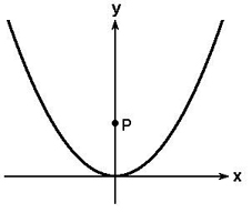
FIGURE PR-2.
The equation describing a parabola is y = x2 / 4P where P is a constant, as shown on the graph. What’s so special about a parabola? It’s all about that point P, called the focal point. Imagine a bunch of ball bearings rolling across a table in straight lines parallel to the y-axis and hitting the inside of the parabola, which is lying on its side. All the ball bearings would bounce off the parabola and land at point P as shown in Figure PR-3. They are reflected to the focal point.

FIGURE PR-3
If we rotate the parabola around the y-axis, we get a three-dimensional figure: a parabolic dish. (New technology? No; the properties of a parabola have presumably been known since the time of Euclid.) Parabolic reflectors are characterized by their focal length: the shorter the focal length, the deeper the dish. In terms of the graph in Figure PR-2, the focal length is how high up the y-axis the point P is located.
Instead of ball bearings, energy in the form of waves can also be concentrated at a focal point using a parabolic reflector. The size of the reflector depends on the wavelength of the waves your trying to focus. Wavelength is how far a wave travels during one cycle of the wave, and is represented by the Greek letter lambda (λ). We define wavelength as:
λ = s / f
where s is the speed of propagation and f is the frequency of the wave. For best reflection, the diameter of the dish should be much bigger than λ. With RF microwaves, the wavelength is a few centimeters. With light, the wavelength is in nanometers. But with sound, the wavelength at 1000 Hz is about 34 centimeters (one foot). Because human detectable sounds can have frequencies from 100 Hz to 20,000 Hz, the wavelength can be equal to the diameter of the reflector at some frequency. Also, since sound is a longitudinal wave, the wavelength can interact with the focal length to cause cancellation at a specific frequency.
A large, deep dish reflector would be best for sound waves. But a 10 foot dish would not be hand-held, so some trade-off has to be made between the size of the dish and its ability to focus sounds.
Noise in Op-Amps
Basically, electronic noise is a bunch of sinewaves with random frequencies and amplitudes. All electronic components generate noise; even wires. Some noise is due to the random vibration of atoms due to temperature. Some noise is generated as electrons move through semiconductors. In all cases, the noise energy is distributed over a range of frequencies. Note that it’s noise power that’s important. A distinction is made between noise and interference. Noise is due to random physical processes while interference is man-made.
Noise in an op-amp is specified on its datasheet in units of nV/√Hz referenced to the input, meaning you multiply it by the gain of the circuit to find the noise on the output. Why does it include Hertz? Because the noise is spread over a range of frequencies. Why is there a square-root involved? Because power is proportional to V2 (P = V2/R). If you take V/√Hz and square it you get a number that is essentially power per Hertz. Then if you multiply that number by the bandwidth of the amplifier you get the noise power.
The TL071 data-sheet specifies 18 nV/√Hz of noise. But look at Figure NSB-1. From about 500 Hertz and up, noise is 18 nV/√Hz. But as frequency drops below 500 Hertz, the noise spec increases. We are seeing something called (for obvious reasons) 1/f noise. In semiconductors, 1/f noise seems to be due to the way electrons interact with randomly distributed impurities in the silicon. It’s interesting to note that 1/f type noise occurs in random processes of many physical systems besides electronic devices; for example, brain waves.
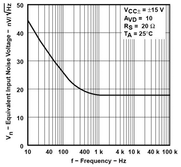
FIGURE NSB-1
How significant is 1/f noise? It depends on the bandwidth your using. The frequency below which 1/f noise starts to increase is called the noise corner frequency (fNC). If your application is at frequencies around fNC, then 1/f noise is important. If your application is at frequencies that are mostly above fNC, then it isn’t so important.
PARTS LIST
| ITEM |
DESCRIPTION |
QTY |
| R1 R6 |
10K - 5%, 1/4W carbon film |
2 |
| R2 R3 R4 |
100K - 5%, 1/4W carbon film |
3 |
| R5 |
510K - 5%, 1/4W carbon film |
1 |
| R7 |
5K - Pot Audio Taper |
1 |
| R7 |
Pot Knob |
1 |
| R8 |
Jumper |
1 |
| R9 R10 |
10 - 5%, 1/4W carbon film |
2 |
| R11 |
1K - 5%, 1/4W carbon film |
1 |
| RX |
2K - 5%, 1/4W carbon film |
1 |
| |
|
|
| C1 C5 |
1 µF, Monolithic |
2 |
| C2 |
220 pF, Monolithic |
1 |
| C3 C10 |
0.1 µF, Monolithic |
2 |
| C4 |
27 pF, Monolithic |
1 |
| C6 |
100 µF, 10V |
1 |
| C7 |
10 µF, 16V Tantalum |
1 |
| C8 |
0.047 µF, Monolithic |
1 |
| C9 C11 |
330 µF, 16V |
2 |
| CX |
2.7 nF, Monolithic |
1 |
| |
|
|
| D1 D2 |
1N4148 (1N914) |
2 |
| D3 |
1N751A |
1 |
| |
|
|
| IC1 |
TL071 |
1 |
| IC2 |
LM386 (8 pin dip) |
1 |
| IC1SO IC2SO |
Eight pin IC socket |
2 |
| |
|
|
| Mic |
Microphone |
1 |
| J1 |
2.5 mm Mono Jack |
1 |
| J2 |
3.5 mm Stereo Jack |
1 |
| PCBs |
Set of 3 Printed Boards |
1 |
| ON/OFF Switch |
|
1 |
| Battery Holder |
|
1 |
| Pot Conn. Cable |
3 Wire Connector & Cables |
1 |
| Red Wire |
Positive Leads |
10" |
| White Wire |
Negative Leads |
4" |
| Black Wire |
Battery Negative Lead |
5" |