With TJ Byers
Breathless in Seattle
Question:
I’m looking for a diagram which would act as an on/off switch by detecting air movement. In other words, it would turn on whenever it detects air movement and turn off when not detecting air movement. The switch has to be sensitive enough to react to a desktop fan or the air movement from a door opening.
Anonymous
via Internet
Answer:
For this kind of sensitivity, I suggest using thermistors to detect air movement. Thermistors have long been used to monitor gases of all sorts because they react quickly to changing temperatures. Basically, a thermistor is a temperature-sensitive resistor of which there are two types: those that increase resistance as the temperature rises (PTC) and those that decrease in resistance as the temperature rises (NTC). For this project, we use NTC (Negative Temperature Coefficient) thermistors.
A characteristic of the NTC thermistor is that, when you pass current through it, it dissipates power — heat. This causes the resistance to decrease, which allows more current to flow, which results in more heating. At some point, the amount of self-heating equalizes the heat dissipated to free space (air).
Herein lies the principle of air flow detection. Different gases — helium and nitrogen, for example — dissipate heat at different rates, which can be measured via thermistors. When you add air flow (chill factor), the cooling rate is even more pronounced. That is the heart of this sensor.
R1 and R2 in the schematic below represent the two NTC thermistors in this design. One thermistor (R2) is sealed inside a wind-proof cage that has access to outside ambient air. My favorite shield is an upside-down prescription bottle with an open bottom and a couple of small holes drilled at the top for ventilation. This allows R2 to heat the air around it for a reference. R1 is also subjected to the self-heating effect, but, this time, it’s exposed to ambient air — including cooling via air currents.
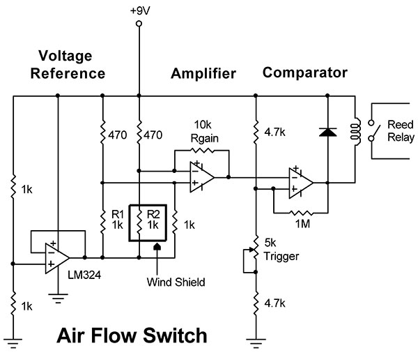
The first stage uses the LM324 op amp to establish a virtual ground. The next section is an amplifier that sets the sensitivity via Rf. Using a 10K resistor, the gain is about 10. The output of this stage goes to a comparator, which closes the reed relay when air flow is detected by R1. The trigger potentiometer adjusts the trip point.
Making this circuit work will take some effort on your part. That is, you have to increase or decrease the value of Rf to get the sensitivity you desire, which, in turn, causes readjustment of the trigger pot.
Comments