With TJ Byers
Follow the Debouncing Ball
Question:
I'm interested in mechanical switch contact bounce. I have been very successful in accounting for contact bounce using software, but have never tried to eliminate it in hardware. I recently read a statement in a book about electronic circuits that said switch contact bounce could “easily be eliminated by the fitting of a small capacitor” into the circuit. No details were given. I experimented for hours at the oscilloscope using a variety of capacitors, but never came close to eliminating the contact bounce. Are you familiar with using a capacitor to eliminate bounce? If so, how do you determine the value of the capacitor, and how is it placed in relation to the switch?
— Judy May W1ORO
Union, KY
Answer:
All mechanical switches and relays have leaf-like contacts with mass and flexibility. Because of these properties, the contacts will “bounce” upon closure for a period of up to 20 milliseconds (ms) before coming to rest and providing an unbroken contact. (Contact bounce can also occur when the switch opens, to a lesser extent.) During this time, the switch can send many pulses to the input of a microcontroller or logic gate, creating false triggering.
There are several methods to eliminate contact bounce — including the software routines you have mastered. At the hardware level, contact bounce is eliminated using RC time constants. When a resistor and a capacitor are paired, they form a time-dependent network, as shown in Figure 1(a). When switch S1 is pressed, it shorts out the capacitor and forces the input of the logic gate to ground, which generates an output voltage. When the push button is released, the capacitor charges through the 47K resistor at a rate of t = RC. When the voltage across the capacitor reaches about 3.0 volts, the gate flips logic and the output goes low.
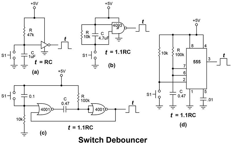
Now how does this help us with contact bounce? If we select the time constant of the RC network so that it takes more than 20 ms to reach 3.0 volts, any voltage excursions of the contact bounce will have their tops lopped off like a lawnmower over grass. The typical debounce time is anywhere between 50 ms and 0.1 seconds. If the resistor is 47K and the debounce time is 50 ms, then the capacitor is 1 µF (C = t / R).
While this design works well for driving most CMOS devices, TTL and low-voltage logic chips require a cleaner pulse. Often a Schmitt trigger (Figure 1(b)) is used in place of an inverter. Unlike a standard logic gate — which has its high and low trigger voltages at three and two volts, respectively — a Schmitt trigger has a greater hysteresis with trip points at 3.3 and 1.8 volts. This wider voltage band lets the Schmitt trigger clean up contact bounce that would otherwise pass through a standard gate. Notice the inverse arrangement of R and C — they are in parallel instead of serial. In this arrangement, C charges when S1 is closed and discharges through R when it opens. When both NAND inputs are high, the output goes low.
For really dirty switches, you need to bring out the big guns — one-shot monostable multivibrators. Monostable multivibrators are sometimes called pulse stretchers because once triggered, the output remains high until the one-shot times out. No amount of hammering on the input can disturb this output in its duties. Figure 1(c) and (d) show two monostable designs. Circuit (c) uses a pair of NOR gates to form the one-shot. Circuit (d) isyour classic 555 monostable multivibrator.
Comments