The Mini-Bench Supply
By Jim Stewart
If you've already built the Switching Regulator and the DC-to-DC Converter, then you have most of what's required. You will need to add a 7805 regulator IC and a capacitor for the +5V output. If you haven't yet built them, NOW would be a good time to dig out those back issues, fire up the old soldering iron and get started. Of course, if you have digital access to N&V, you're only a click away!
You will also need the following: • Enclosure • Binding Posts • On/Off Switch • Indicator • Wall-mount DC Module
The Enclosure Although most any enclosure of sufficient size will work, the one I used for this project is made of 0.046" industrial-grade aluminum and has four soft plastic self-adhesive feet. (Top photo) Its dimensions are 6" wide, 3" high, and 4" deep. It's a simple assembly with the top attaching to the base with four #4 self-tapping screws; two on each side. As luck would have it, this very enclosure is available from the NV webstore and already has holes for the boards, a toggle switch, and an indicator LED. However, it does not have holes for the binding posts, so you will have to cut those yourself.
Mounting the Binding Posts Most binding posts (Figure 2A) have two flats on the threaded part which requires a Double-D hole as shown in Figure 2B. The flats prevent the posts from coming loose under the constant tightening and loosening of their caps.
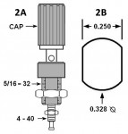
Unless you have a double-D punch, you will have to drill 1/4“ holes and use a file to get the 0.328” (21/64) dimension. If you'd rather not do all that filing, you can just drill (or ream) 0.328" holes and secure the posts with a strong two-part epoxy. After all the holes are made, you can use some steel wool to give the box a matte finish, or you can spray-paint it.
The top photo shows the binding posts mounted on the front of the box. Use a carpenter's square and a pencil (or a scribe) to draw a line across the middle of the box front. Mark a spot along the line that is 1.25" from the left edge. Then, mark a second hole 0.75" to the right of the first hole. Repeat for the next three holes. Use a punch to make an indent at each mark. Then, drill a 1/16" hole at each mark. Expand each hole with a 1/8" drill, and then with a 1/4" drill. After that, it's FTF (file to fit) to make the double-D holes for the posts.
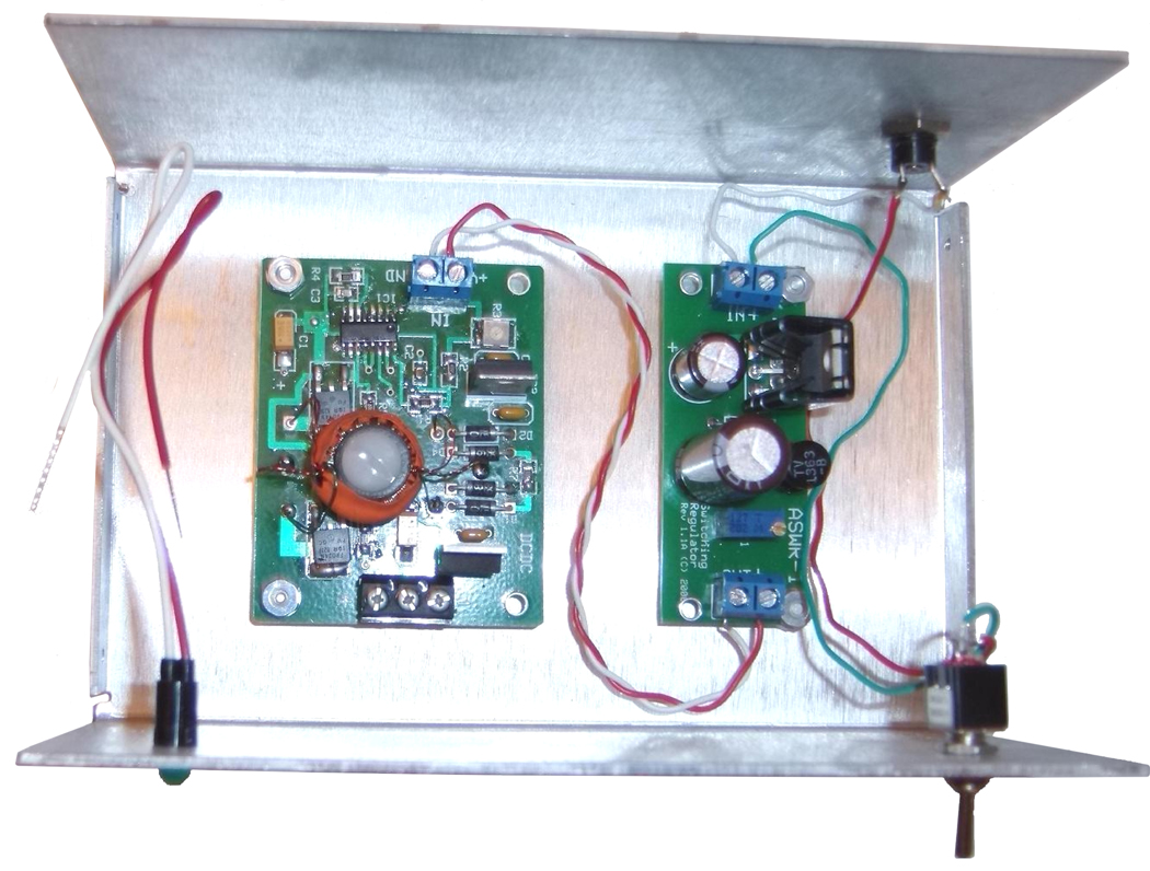
This style of post is called a "5-way" binding post because you can connect to it with a: 1. Banana plug 2. Spade lug 3. Pin end 4. Alligator clip 5. Wrap of bare wire Mounting the Boards Figure 3 shows the switching regulator and the DC-to-DC converter mounted in the box using 4-40 X 1/4" aluminum hex stand-offs. Two of the pre-punched holes are used for each board which should be secure enough for bench use. A toggle switch and an LED indicator are mounted in the pre-punched holes in the front. In the back is a pre-punched 1/8" pilot-hole.
Some indicators have a built-in resistor; they specify what voltage to use (+5 or +12). Others require you to add the resistor. Assuming you are connecting to the +9 volts and assuming a drop of about 1.5 volts across the LED, a 330Ω, 1/4W resistor should do the job. To add a 1/4W resistor, cut the red lead on the LED about 1" from the indicator body. Trim the resistor leads to about 1/4". Solder one end of the resistor to the red indicator wire. Solder the other end to the piece of red wire you just cut off. Slide a piece of heat shrink tubing over the wire so that it covers the resistor and the bare leads, and apply heat. Or, you can wrap the resistor with electrician's tape.
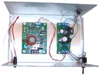 Figure 3
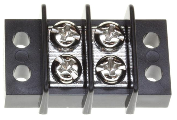
Attaching the Power Module Wall supplies come with different size power plugs. I just happened to have an insulated power-jack that was a match to the power plug on the supply I used. The simplest way to connect it is to drill out the pilot hole to accept a 1/4" rubber grommet. Then, cut the plug off the wall supply and feed the wire through the grommet. Inside the box, tie a knot in the wire for strain relief. Another approach is to attach a terminal block (Figure 4) to the back of the box and run wires from one side of the block through the grommeted hole. Then you could attach various power sources, even a 12V battery, to the other side of the block.
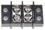 Figure 4
Inside the box, run the positive wire to one pin on the toggle switch and the other wire to the GND input on the switching regulator. Then, run a wire from the other pin on the toggle switch to the +V input of the switching regulator.
*Note that on the DC-to-DC board, a jumper wire is required between the input ground and the output ground.
Power up the Switching Regulator and adjust the output to +9V. Then, turn off the power and connect the output of the Switching Regulator to the input of the DC-to-DC converter. Now you need to add a 7805 regulator, which can be mounted to the inside of the box. It will require an insulator pad (Digi-Key #BER214-ND) and a nylon screw and nut. Or, you could solder the 7805, (with a push-on heat sink), to a piece of proto-board and then mount the proto-board inside the box. Either way, you'll need a capacitor (e.g., 100 uF @ 10V) from the output of the 7805 to GND. Next, wire the output voltages to their corresponding binding posts and test before you attach the cover.
Output Power You'll need a wall mount supply module with an output of at least 12V DC. The power you can draw from the mini supply depends largely on how much power the module can supply. Using a surplus module made by AULT that supplies 15V DC @ 1,000 mA, I was able to continuously draw 0.5A from the +5 output and 0.25A from the +12 and -12 outputs - all simultaneously. I could have drawn more current.
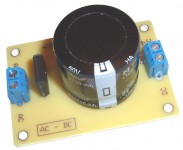 Figure 5
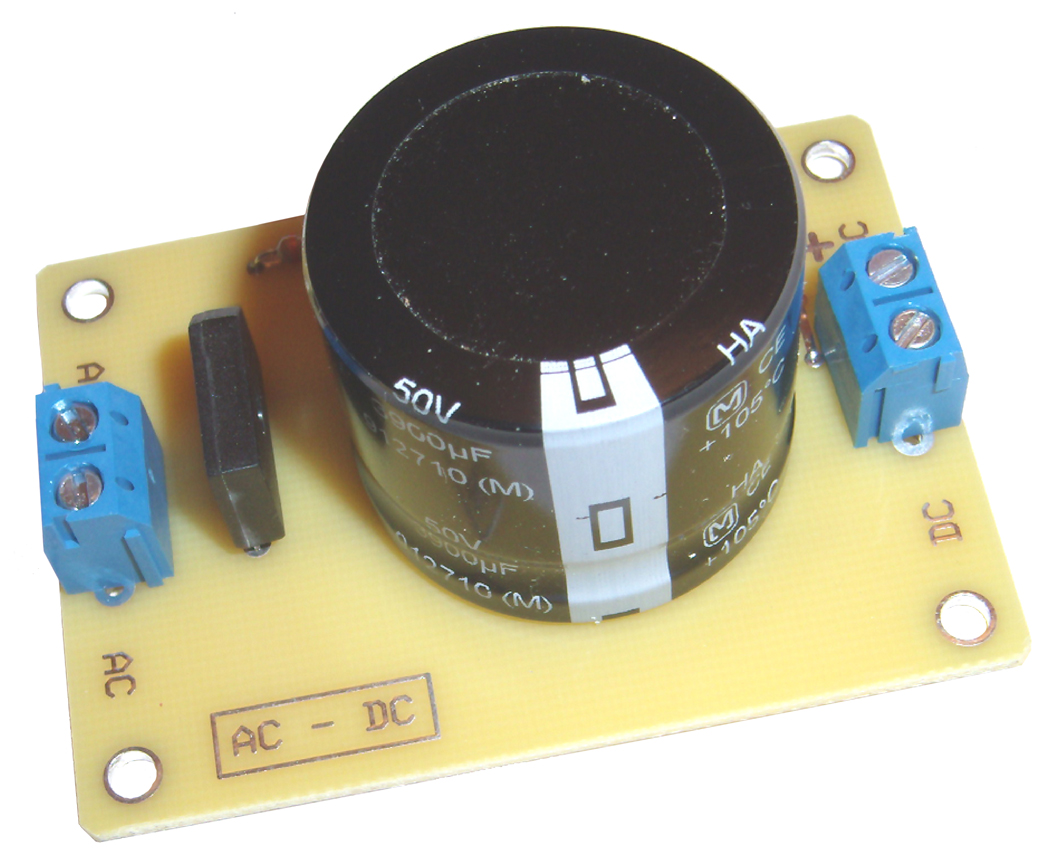
I used a surplus unregulated DC wall mount supply. Regulated units cost more and don't add anything to performance. Sometimes you can find surplus AC output wall supplies that are very inexpensive. They're basically just transformers. To use one, you would have to add a bridge rectifier and filter cap. The filter cap (C3) on the PS3 would be too small. You'd need a rectifier-filter similar to the one in Figure 5 with a 3,900 uF, 50V DC cap.
Wrap Up You now have a useful piece of bench equipment, and you built it yourself! Plus, you got to practice your skills at working with sheet metal. Have fun with it and see if you can dream up other applications for the Switching Regulator, the DC-to-DC Converter, and even the aluminum enclosure.
Build It Today! A PCB or complete kit for both the Switching Regulator and the DC-to-DC Converter are available for purchase from the Nuts & Volts webstore. Also, a complete kit for the Mini-Bench Supply which includes both the Switching Regulator and DC-to-DC Converter kits, enclosure, and Mini-Bench accessories kit, is now available at a special combo price!
Switching Regulator
DC-to-DC Converter
Aluminum Project Enclosure
Complete Mini-Bench Supply Kit
Purchase PCBs or complete kits!
Comments