This article builds on the previous “Translational Reality Interfaces” piece in which a toaster equipped with a translational reality interface (TRI) enabled a user to control an irrigation pump. In this article, I’ll show you how a classic video game can be adopted for use as a TRI to enable the player to monitor and operate a remote device by simply playing Pong.
Life is Just a Game
In Part 1, I mused that one day some of us will play our favorite video games and, in so doing, operate a remote device that could be hovering over a battlefield or in an operating room. Assuming the games are fun, that’s not a bad way to earn a living or at least some extra income. The aim of this article is to illustrate that the technology necessary for this work-play scenario is here today, in the form of translational reality interfaces.
Recall from Part 1, that translational reality is a closed loop/real time interface. In the example shown in Figure 1, the gamer or user plays a game of Pong on a PC/Mac and in doing so, controls a remote lamp that operates on a particular logic.
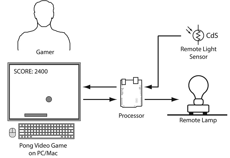
FIGURE 1. Video game translational reality interface, enabling the user to monitor and control a remote lamp.
The signal from a remote light sensor causes changes in the video game, requiring the user to take action to avoid losing points and/or to gain points.
The two major elements in this example — the video game and the lamp — were chosen because of their simplicity. It’s hard to find an example of a game simpler than Pong, and a lamp or LED is often the indicator of choice when debugging a microcontroller. Still, what the game and lamp represent is important. Substitute a more substantial game and more complex remote device, and you could have a system that’s actually practical. For now, let’s get the simple framework working so that you have an experimental platform.
Game Play
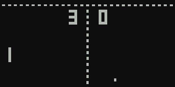
Pong was understandably the game that put Atari on the map. You simply slide the paddle horizontally to intercept the bouncing ball to keep it in play. Miss the ball and you lose points or the game.
I’ve added a few twists to the basic game to make it part of the translational reality interface. There are two states, identified by the color of the paddle and ball. When they’re white (as in Figure 2), game play is normal. Points accumulate for successful intercepts, at the rate of 100 points/intercept.
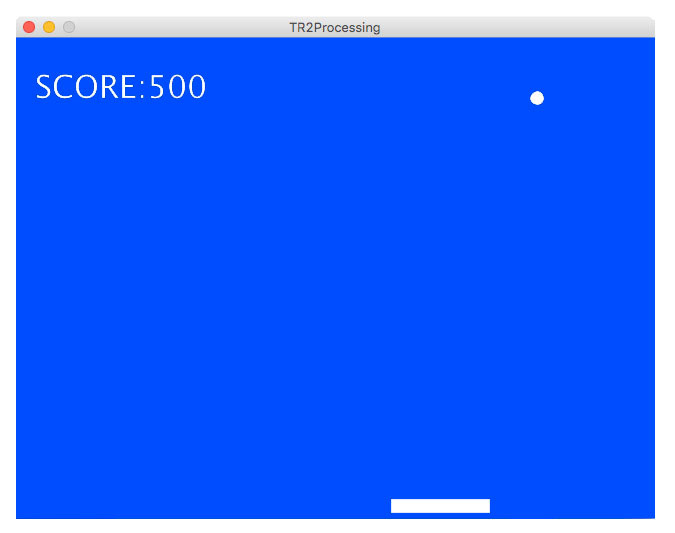
FIGURE 2. Pong game interface, coded in Processing.
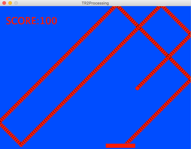
However, when the ball and paddle turn red (signifying an alarm/alert condition at the remote site), the user must hold down the space bar while intercepting the bouncing ball with the mouse-directed paddle. Fail to hold down the space bar during the moment of impact with the paddle and the score is returned to zero. However, if the user manages to hold down the space bar while moving the paddle (with the mouse) under the bouncing ball, then the score increases by 1,000.
As currently configured, the gamer is allowed three misses per session. However, as with the background color, size of the ball, and other aspects of the game, everything is customizable by changing a few lines of Processing code. This graphic shows the Pong game with the screen refresh disabled.
If you haven’t played Pong before, perhaps you can appreciate the simple geometry involved in game play. With a little practice, you should be able to move the paddle to where the ball is going before it gets there.
Hardware
The hardware requirements for this project are minimal, assuming you have a desktop or laptop computer and an Arduino-compatible microcontroller. I use the popular Uno in this example. As shown in Figure 3, the Uno is connected to a CdS (Cadmium Sulfide) photoresistor, a 10K resistor, and a 220 µF at 10V electrolytic capacitor.
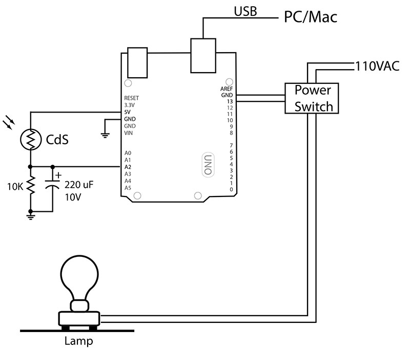
FIGURE 3. System schematic.
In the dark, the resistance of the photoresistor is several million ohms. Resistance drops to 1K or lower with illumination.
When the photoresistor is illuminated, the 220 µF capacitor is charged by the Arduino’s 5 VDC source. When illumination is withdrawn, the photoresistor is essentially an open circuit, and the voltage across the capacitor and resistor combination follows the expected 1/RC time constant. The decaying voltage level is read by analog pin A2 on the Arduino.
On the digital side of the Arduino, the voltage across pin 13 to ground is used to signal a PowerSwitch II (Sparkfun.com) which switches on 110 VAC whenever pin 13 is HIGH. Figure 4 shows the three peripheral hardware components.
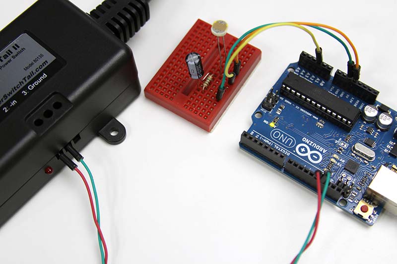
FIGURE 4. Peripheral hardware components: PowerSwitch II, CdS sensor, RC circuit, and Uno.
The use of the PowerSwitch II is simply for flexibility. If you read Part I of this series, you know that there are a variety of second devices that can be controlled by the interface. With the PowerSwitch II, you could plug in and control just about any home appliance or light fixture, from a table lamp to a blender or a toaster.
Assuming we keep it simple and use a lamp, the photoresistor will work fine as a monitoring sensor. If you opt for a different output device, then you’ll have to modify the sensor electronics accordingly. Given the simplicity of the design, that shouldn’t be an issue.
Software
Working with both Processing and an Arduino microcontroller lends itself to parallel software development as shown in Figure 5.
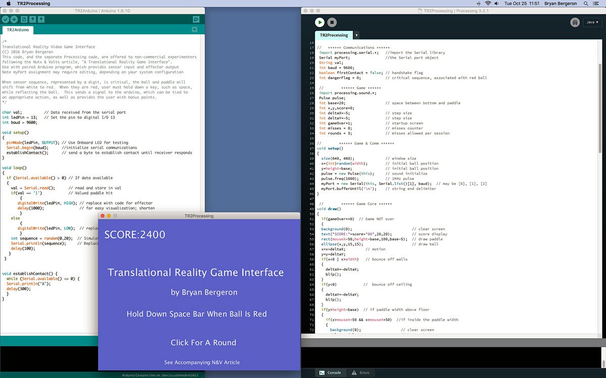
FIGURE 5. Software development environments, with Arduino IDE (left) and Processing IDE (right). The purple startup screen is running in the lower left.
Assuming you have the screen real estate, having both IDEs (integrated development environments) and the executing game visible simultaneously supports rapid development and debugging. What’s more, because the languages are essentially identical, you don’t need to rethink logic or control construction from one IDE to the other. That said, the Processing IDE is more advanced, with little niceties such as line numbering.
The program for the Arduino is shown in Listing 1. For clarity, the code is uncommented here. However, the source file in the downloads is heavily commented.
char val;
int ledPin = 13;
int sensorPin = A2;
int sensorValue = 0;
int baud = 9600;
void setup(){
pinMode(ledPin, OUTPUT);
Serial.begin(baud);
establishContact();
}
void loop(){
if (Serial.available() > 0)
{
val = Serial.read();
if(val == '1'){
digitalWrite(ledPin, HIGH);
delay(1000);
}
else
{ digitalWrite(ledPin, LOW);
}
sensorValue = analogRead(sensorPin)/50;
Serial.println(sensorValue);
delay(100);
}
}
void establishContact() {
while (Serial.available() <= 0){
Serial.println("A");
delay(300);
}
}
LISTING 1. Arduino source code.
As you can see, the code is straightforward, right out of the example files from the Arduino IDE. After defining the variables, the setup routine is run, which begins the serial communications and calls the subroutine to establish contact with the serial port on the Mac/PC.
The main loop continually checks the serial port. If it reads a “1” from the computer, then pin 13 — which is connected to the onboard LED — is set HIGH. The LED and relay within the PowerSwitch II are energized. The lamp connected to the PowerSwitch II is energized. Conversely, if something other than “1” is received, then pin 13 is set LOW, and the LED and PowerSwitch II are de-energized.
Next, the external sensor attached to the sensor pin — analog pin A2 — is read, and the result scaled down by a factor of 50. The resulting value is sent over the serial port to the computer hosting the Pong game. This is the one point in the Arduino code that you might want to modify; either to change the divisor to reflect your environment and/or component specifications, or to increase the complexity of the pattern you want to monitor.
For example, instead of a single analog value, you might want to monitor a string of different sensors read in a particular sequence.
Note that there's nothing special about digital output pin 13, other than it’s useful during debugging because of the onboard LED. If you’re concerned about excessive load on pin 13, then move the external device to a different output pin and change the code accordingly. The PowerSwitch II draws only a few mA, so the load on the pin isn’t an issue.
The Processing code (the highlights of which are shown in Listing 2) is necessarily more involved than the Arduino code.
Import processing.serial.*;
import processing.sound.*;
void setup(){
myPort = new Serial(this, Serial.list()[1],
baud);
myPort.bufferUntil('\n');
}
void draw(){
if(gameOver==0){
ellipse(x,y,15,15);
x=x+deltaX;
y=y+deltaY;
if(x<0 | x>width){
deltaX=-deltaX;
blip();
}
if(y<0){
deltaY=-deltaY;
blip();
}
if(y>height-base){
if(x>mouseX-50 && x<mouseX+50){
background(0);
deltaY=-deltaY;
blip();
score++;
if ((dangerFlag ==1)&&(keyPressed==true)){
fillWhite();
score = score + (dangerFlag * 10);
myPort.write('1');
}
else
{ if(dangerFlag==1){score = 0;}
myPort.write('0');
}
dangerFlag = 0;
}
else
{ misses++;
deltaY=-deltaY;
blip();
if (misses > rounds){
gameOver=1;
misses = 0;
}
}
}
}
}
void serialEvent( Serial myPort){
val = myPort.readStringUntil('\n');
if (val != null){
val = trim(val);
if (val.equals("2")){
dangerFlag = 1;
fillRed();
}
if (firstContact == false){
if (val.equals("A")){
myPort.clear();
firstContact = true;
myPort.write("A");
}
}
else
{myPort.write("A");}
}
}
void gameOverSplash(){}
void mouseClicked(){}
void blip(){}
void screenBlue(){}
void fillRed(){}
void fillWhite(){}
LISTING 2. Highlights of the Processing source code.
Because of space limitations, only the highlights of the code are shown, and there are no comments. As with the code for the Arduino, a fully documented version is available in the downloads.
Starting at the top, two libraries are loaded: the serial library and sound library. The serial library is required for communications with the Arduino, and the sound library supports the “blip” that occurs whenever the ball impacts a wall or the paddle.
Key elements of the setup routine are setting up the serial communications port on your desktop computer and establishing “\n” as the string terminator. Depending on your computer port configuration, you may have to change the serial list assignment from 1 to 0 or 2 or 3.
The draw routine is concerned with both game graphics and communications with the Arduino. It defines the size of the ball (15x15 pixels), increments the X and Y position of the ball with time, causes the ball to reverse direction on impact with a wall or the paddle, and communicates with the Arduino. It writes a “1” to the Arduino if the user is successful in rebounding a red ball, and changes the color of the ball back to white.
The serialEvent loop looks for a danger or alert condition from the Arduino, signified by a “2.” In the current configuration, when the voltage across the 220 µF capacitor drops significantly, the value read by A2 is eventually “2.” The color of the ball and paddle are changed to red, and the player must hold down the space bar — or other key — when moving the paddle with the mouse to intercept the ball.
The subroutines called by the main program are listed by title only. The full definitions appear in the actual source code. There are subroutines for changing the color of the ball and paddle, for putting up the splash screen at first launch and after each session, and for playing sound effects.
Taking It from Here
An obvious next step is to experiment with controlling and monitoring different devices through the Pong game interface. A heater element/thermistor pair would work, for example. Then, there’s the extension of the monitoring code to include sequences and various scaling functions so that it’s not simply the decayed signal from an LED or lamp.
The point is to have a sequence or single value that requires human attention/decision making and reflect that in real time game play.
A next step is to increase the complexity of the game design. Add levels. Increase the level of difficulty. Add more interactive elements — and tie these to actions on the controlled device.
Are you going to be able to control a factory assembly line by playing Pong? Perhaps not. However, with more advanced game play and decision logic, just about any level of control is possible. Furthermore, even if you aren’t interested in the various aspects of translational reality, learning how to use Processing to move data from the environment into a computer and back again is a skill worth learning. NV
Translational reality is a real time/closed loop system in which a user operates a familiar first device (e.g., a video game) and, in so doing, both monitors and controls a second device. User feedback is appropriate to the first device — game play and scoring, for example — but depends on the operation of the second device.
Processing is a free open source interactive programming language with an integrated development environment (IDE). Because it’s designed to teach the fundamentals of computer programming in a visual context, it’s extremely easy to learn and use. As a bonus for Arduino users, if you know how to program the Arduino, you know how to program in Processing. Furthermore, there are libraries for communicating between a computer running MacOS/Windows/Linux and an Arduino microcontroller. To download and learn more about Processing, go to processing.org.
Atari introduced Pong in 1972 as their first arcade game. It was one of those accidental successes in that it was the result of a training exercise assigned to Allan Alcorn by the co-founder of Atari, Nolan Bushnell.
Downloads
What’s in the zip?
Arduino source code
Processing source code