A Car Parking Assistant
It's great to replace your old beat-up car with a brand new one, but when you first bring it home and find that it's a tighter fit in your garage than the old one, you may have a problem. In my case, the new car was a bit longer, and it was a challenge to get it into that sweet spot where it was in far enough to close the garage door, but not so far that I bumped into the storage shelves on the back wall.
I know, I know ... a tennis ball suspended from the ceiling at just the right spot is the classic solution, but with more than one person using the garage — possibly driving different cars or just backing in — that just wouldn’t cut it. Also, it would be in the way for somebody walking through the empty garage.
Some of the commercial garage parking aids that I reviewed also had their drawbacks: One system used a laser beam shining down onto the dashboard of the car; others had only a limited range of adjustment or warning lights that were too dim. The situation seemed ripe for a custom electronic solution.
The System’s Approach
I’m always attracted to projects that involve firmware as well as hardware development, and it seemed that a microcontroller — plus some way to sense the location of a car — would be a good start. As feedback to the driver of the car, I envisioned a series of bright lamps mounted on the rear garage wall which would come on as the car passed through three “zones:”
- When the car was nearly inside the garage
- When it was in the prime parking area — which I think of as the “comfort zone”
- When it had gone too far and was close to hitting the wall
This job is simple enough that almost any microcontroller would do. I have used the Propeller multi-core processor by Parallax ([url=http://www.parallax.com]http://www.parallax.com[/url]) for a few projects, and a survey of my supply cabinets turned up an unused Propeller USB project board. This board features — in addition to the Propeller microcontroller unit (MCU) — voltage regulators, clock crystal, USB interface, and a good-sized area for additional components. It would be ideal for this application.
I began to kick around ideas to sense the distance to a car. I considered a motion detector or a diode laser beam reflected off the front of the oncoming vehicle. Neither approach seemed accurate enough, and the laser spot idea wouldn’t work if you backed the car in. I could also anticipate setup problems with these schemes.
Eventually, I settled on a non-contact approach using an ultrasonic range finder to measure distance. Parallax sells these devices, good for distances up to three meters (about 10 feet), so I sent for one.
Next, my thoughts turned to the signal lamps. These had to be bright enough to be easily seen in broad daylight. I stewed about this for a time, considering and rejecting several ideas; for instance, using relays to control incandescent bulbs. I found my answer in a local automobile parts store. For just a few dollars each, I was able to pick up some running lights — also knows as clearance lights — of the type used on big truck trailers. These lamps contain several high-intensity LEDs; are very visible — even in bright sunshine; and run nicely on 9–16 volts DC. The lamps come in two colors (red and amber), so I bought one of each and decided I would use firmware to show when the driver had strayed into the third zone (mentioned above) and needed to back up.
Refining the Idea
I didn’t want the system to run 24 hours a day — mainly as a power conservation measure — but also to turn off the ultrasonic pinger when it wasn’t needed, since bats, moths, and (I suppose) other creatures are sensitive to these frequencies. So, I looked for some way to apply power to the system when the garage door opened, leave it on for a few minutes while the car was being parked, and then automatically shut down.
A micro switch activated by the garage door opener was the most direct approach. However, there were some mechanical difficulties involved in my case, so I began looking for another plan. Like most overhead garage door systems, mine features an overhead lamp which turns on when the door opens and remains on for about five minutes. Just what I wanted!
To avoid any modification or direct connection to the existing door opener (and possible grounding and safety problems), I decided to go with an inexpensive cadmium sulphide (CdS) light-sensitive resistor which I would locate inside the overhead light fixture, close to the bulb. The change in resistance when the overhead light came on would turn on a MOSFET which would apply power to the MCU board and the signal lights.
Now, I felt I had the basic system design pinned down. With the huge capability inherent in the Propeller and the ease of programming it, any reasonable refinements could come later.
A Few Preliminary Tests
My first priority was to see if the components I had in mind were adequate for the job.
First, I checked the current requirements for the LED lamps and found them to be fairly modest — only about 40 milliamps at 12 VDC for each lamp. Adding in 30 milliamps for the ultrasonic range sensor and 20 mA for the Propeller microcontroller board meant that the whole thing could easily be powered from a small wall wart power supply. Next, I soldered about 30 feet of twisted pair to the terminals of the CdS photoresistor and mounted it inside a clear plastic bottle. Refer to Figure 1.
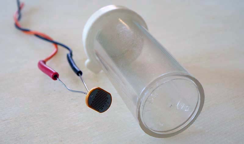
FIGURE 1. Cadmium sulfide photoresistor and plastic bottle ready to receive it.
I fastened it with tape inside the garage door opener overhead lamp close to the bulb, and hooked up my digital multimeter to measure the resistance. I was pleased to see that with the overhead light off, the meter read over one megohm; when the light was lit, the resistance dropped to less than 20K ohms. Plenty of range for switching a MOSFET!
I had no qualms about the Propeller MCU chip. From other projects, I knew it had more than enough capability for this job, since only four I/O pins are needed: two for the LEDs; one for the ultrasonic sensor; and one for a pushbutton switch used for calibrating distance (more on that later). Processor speed is not an issue either for this task.
The Circuit Design
At this point, I felt I had enough of a handle on things to go ahead with the actual circuit design. The system block diagram in Figure 2 shows how the major components work together.
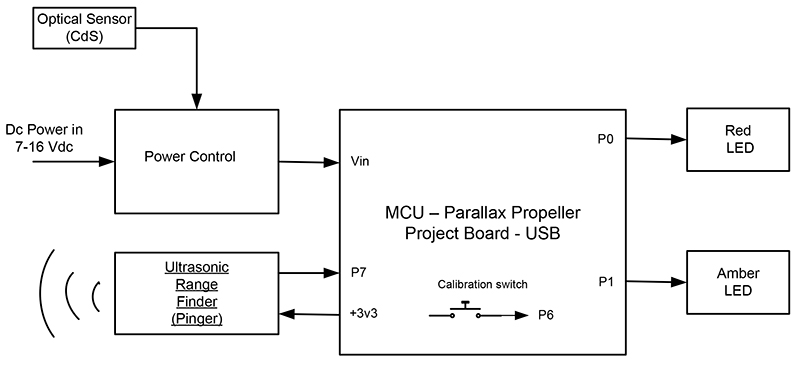
FIGURE 2. System block diagram.
The system block labeled “Power Control” contains a P-channel MOSFET whose function is to switch power to the rest of the circuit under control of the optical sensor. In other words, it acts as a solid-state relay.
Circuit details are shown in the schematic in Figure 3.
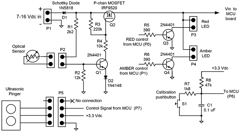
FIGURE 3. Electrical schematic. All components shown here (except for the pinger and optical sensor) are through-hole devices and are mounted in the prototyping area of the Propeller USB project board.
The NPN transistor, Q1, is driven to cut off when the sensor is dark; i.e., when its resistance is high. This allows the gate of the MOSFET, Q2, to be pulled high, turning off Q2 and thus cutting off power to the rest of the circuit. The only current drain now is a few microamps due to leakage through the MOSFET and the photoresistor. Diode, D2, in the emitter of Q1 is there just to ensure that Q1 cuts off completely — even if there may be a slight leakage of light onto the sensor — as on a bright sunny day with light streaming through the garage window.
Note that an NPN Darlington transistor — a BC517, for example — could be used in place of the Q1/D2 combination since the Darlington inherently has a higher base-to-emitter forward voltage drop (Vbe) than the 2N4401. I just used what I had available.
The LEDs get their power directly from the raw DC input. As mentioned previously, each LED lamp uses about 40 mA when it’s on and is controlled by a 2N4401 switching transistor. There is nothing critical about these transistors, and almost any NPN capable of handling a collector-to-emitter voltage (Vce) greater than the input supply voltage will do.
Momentary normally open (NO) pushbutton switch, S1, simply provides a user input signal for use during the calibration procedure. This is explained in the Calibration section of this article. Schottky diode, D1, is in the circuit to prevent any disastrous consequences if the power source is accidentally reversed.
The Pinger
The ultrasonic pinger is an easy-to-use non-contacting distance sensor which operates on the same principle as range-finding radar. Besides power and ground, it uses just a single control pin driven by the microcontroller.
When the control pin receives a pulse from the MCU, the pinger emits a burst of high-frequency (40 kHz) sound. The control pin then outputs a high level until an echo return is received.
The width of the signal from the control pin is the same as the echo time delay, and is therefore a measure of the distance to the reflecting object. Parallax specifies a supply voltage of five volts for the pinger, but I found that the device works with no problems at 3.3 volts. I was prepared to install a level-shifting circuit between the pinger control pin and the MCU using a single-transistor circuit (which has appeared several times in the pages of Nuts & Volts), but it seemed to be unnecessary in this case.
I have included a description of a suitable level-shifter with the information package in the downloads, if you should choose to go that way.
Firmware
The firmware for the garage sentinel project was written entirely in the Propeller Spin language, and is very basic and easy to understand. The program begins by initializing the I/O pins and retrieving the near and far limits of the comfort zone (program variables nearmark and farmark), which have been stored in EEPROM during the calibration process.
Next, it enters an endless loop which repeats every 250 milliseconds, where the first order of business is to check the state of the calibration pushbutton.
If the button is depressed (logic low), a calibration routine (called “method” in the Spin language) is entered. If not, the program sets the MCU pinger control pin as an output and pulses it high for 50 microseconds.
Next, it sets the pin as an input and monitors the duration of the return signal. The duration is converted from system clock counts to distance in centimeters and is stored in the program variable distance.
A series of comparisons follow:
- If distance is greater than 260 cm, both LEDs are turned off.
- If distance is less than 260 cm, the car is approaching the comfort zone and the amber LED is turned on.
- If distance is less than the maximum zone boundary (farmark), the car is within the comfort zone and the red LED only is turned on.
- If distance is less than the minimum zone boundary (nearmark), it’s beyond the comfort zone and the red LED flashes at a rate of twice per second.
The loop then repeats from the beginning.
Calibration
In this mode, the user gets to set the distances marking the near and far limits of the comfort zone for parking the vehicle. These distances are stored in program variables nearmark and farmark, respectively, and also in EEPROM so they can be retrieved every time power is applied to the system. As mentioned in the firmware description, the firmware periodically checks the state of the calibration pushbutton. If the button is pressed, the calibration method is entered. Here, the duration of the button press is captured, and again a series of comparisons is carried out:
- If the button press is less than one second or more than 20 seconds, the calibration method is exited and control returns to the main program.
- If the button press is between one and five seconds, the distance reading is stored in nearmark and in EEPROM, and the calibration routine is exited.
- If the button press is between five and 20 seconds, the distance is stored in farmark and in EEPROM, and the routine is exited.
In practice, the actual calibration procedure is pretty straightforward:
First step: Drive your car slowly into the garage and stop where you consider the beginning of the comfort zone to be. Then, press the calibration pushbutton for more than five but less than 20 seconds. This saves the location in EEPROM and in the farmark program variable.
Second step: Pull the car forward to where you want the end of the comfort zone to be. Now, press the calibration pushbutton for at least one second, but not more than five seconds. This records the nearmark location.
That’s all there is to it!
Hardware
For an enclosure, I went with the neat clear plastic multiboard project box offered by Parallax that is designed to fit the Propeller USB project board. There is plenty of room on the board to accommodate the small number of components required. Figure 4 is a picture of the board populated with all components.
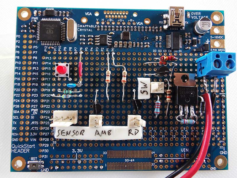
FIGURE 4. The Propeller USB project board with all components mounted. The calibration pushbutton is the red button in the left center of the board. The cable from the optical sensor plugs into the two-pin header labeled "SW."
I needed to bring two external cables into the box from the remotely-located optical sensor and the three-wire cable to the pinger. There are several knockout sections of various sizes convenient for feeding cables into the box. I had to cut a hole in a side panel to mount a DC power coax jack, and another hole to give me access to the USB port on the project board (in case I wanted to modify the firmware after assembling everything).
I mounted the two LED lamps on the front panel of the enclosure where they fit very nicely, as shown in Figure 5.
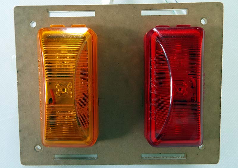
FIGURE 5. The LED lamps mounted on the front panel of the enclosure.
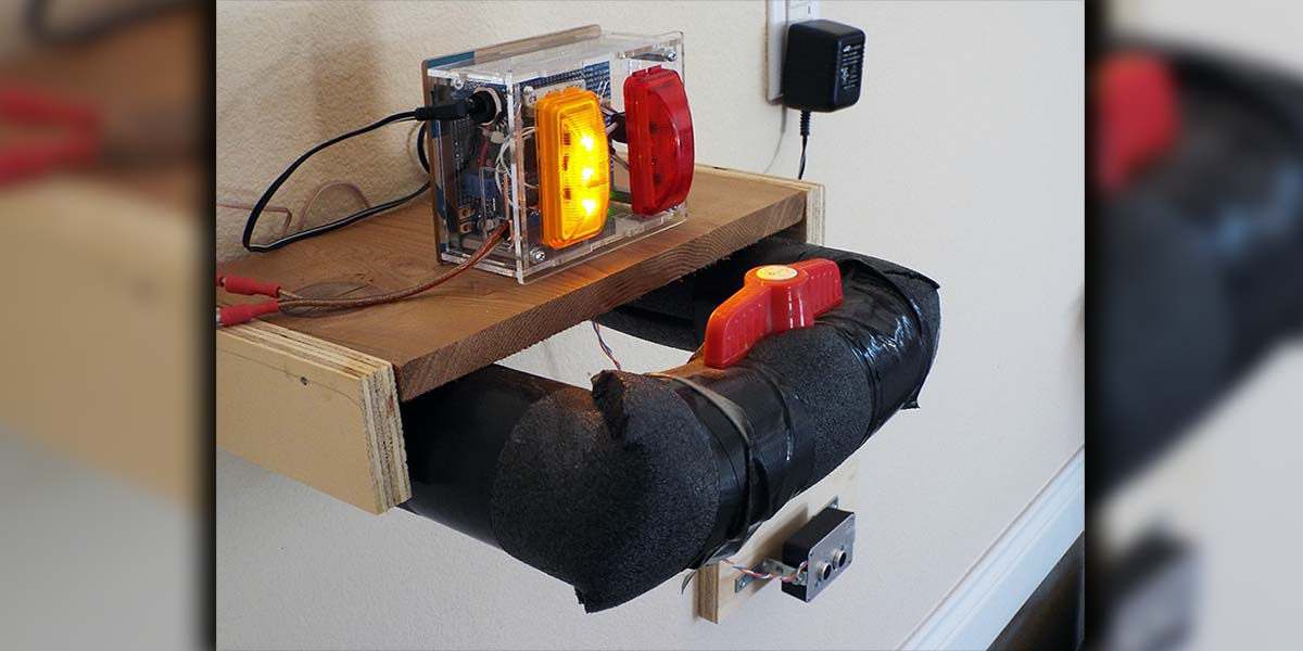
The final configuration of the complete garage sentinel system as set up in my garage is shown at the beginning of this article.
In that photo, you can also see that I put the pinger in a small separate box at the end of a short cable since I had to put it low enough to “see” the front of the car. Of course, the box with the LED lamps had to be high enough for the driver to see it.
To power this project, I used a wall wart type of external power supply, capable of supplying about 200 mA at nine volts DC. One word of caution which applies to any home-built project using this type of power supply: Be sure to check the open circuit voltage (i.e., the unloaded output voltage) at least once before connecting your wall wart to the device you are building.
Some of these supplies can put out nearly twice their rated voltage without a load, and if you turn on the supply before connecting it to your project, the brief over-voltage before it settles down could be extremely bad news to your system.
Temperature Dependence
The ultrasonic pinger used in this project can be utilized to measure distance to nearly any surface — solid or liquid. If perhaps you are thinking of other applications, I should mention here that the performance of the sensor is a bit dependent on air temperature. This doesn’t imply a defect in the pinger’s design; it’s just a property of sound in air.
Sound travels faster in warm air than in cold, and since we’re using the time delay of the return echo to determine the range, temperature can affect the distance reading. The folks at Parallax provide a handy formula on the pinger datasheet for correcting the range measurements. If you are after the ultimate accuracy, you will need to do this compensation.
This means adding a temperature sensor to the system and a bit of firmware to do the arithmetic. Not difficult to do, if you need the accuracy; I chose to ignore this problem for the garage sentinel since my garage stays pretty much between 3 and 50 degrees C, resulting in a possible error of about plus or minus four percent. This amounts to just a few centimeters at the closest approach. Not enough to worry about for parking the car.
Future Upgrades
As mentioned, there is plenty of untapped capability in the Propeller MCU on this project. I can imagine adding a beeper or other audible alarm when the car gets too close to the garage wall as an additional warning besides the flashing LED. Or, another cool feature might be to continuously increase the LED flash rate as the car gets farther past the comfort zone.
Also, it shouldn’t take much to add a second pinger, arranged to give a wider coverage angle. This would be useful if you have a wide garage, or more than one car.
I may build up a future version of this device using some of these upgrade ideas, but for the present it suits my needs as-is. Now, I can always ease the car into the parking comfort zone without hitting anything, and with enough room to walk around the car in front and back after the garage door is closed. NV
Parts List
| Item |
Description |
Value |
Model |
| R1 |
1/4 watt resistor |
2.2K ohms |
|
| R2 |
1/4 watt resistor |
2.2K ohms |
|
| R3 |
1/4 watt resistor |
220K ohms |
|
| R4 |
1/4 watt resistor |
10K ohms |
|
| R5.R6 |
1/4 watt resistor |
390 ohms |
|
| R7 |
1/4 watt resistor |
1.8K ohms |
|
| R8 |
1/4 watt resistor |
47K ohms |
|
| D1 |
Schottky diode |
|
1N5818 |
| D2 |
Silicon diode |
|
1N4148 |
| Q1, Q3, Q4 |
NPN transistor |
|
2N4401 |
| Q2 |
P-channel MOSFET |
|
IRF9520 |
| S1 |
NO pushbutton switch |
2 pins |
|
| P1, P2, P3, P4 |
Male pin header |
4 pins |
|
| P5 |
Male pin header |
|
|
| |
Red high-intensity LED |
|
|
| |
Amber high-intensity LED |
|
|
| |
Propeller USB project board |
|
Parallax P/N 32810 |
| |
Ultrasonic range sensor |
|
Parallax P/N 28015 |
| |
Cadmium sulfide photoresistive optical sensor |
|
|
| |
Multiboard enclosure, clear plastic |
|
|
| |
Power supply (wall wart) |
9-16 VDC 100 mA or greater |
|
Downloads
Basic_I2C.Driver.spin, GarageSenitinel.spin, and Bi-Directional level Shifter.pdf