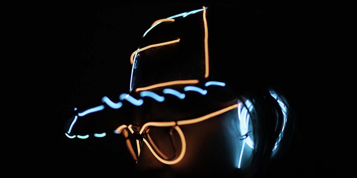
A while back, I had purchased some electroluminescent (EL) wire from LiveWire (www.elbestbuy.com) and used it to decorate a shirt and a hat. The simple “on” or variable-speed flashing controller quickly grew boring. The sequencers had up to five colors of wire, but didn’t allow me to customize the patterns. I wanted more control and creativity, as any self-respecting hobbyist does.
Putting a voltmeter on the inverter output, I found that it used 80 volts AC, driven at 1,600 Hz. I quickly figured out that it was going to take something more than a simple transistor driver to turn it on and off. I tried a couple of miniature relays with limited success, but they were just too bulky and power-hungry for wearable electronics.
I finally found the G3 series of opto-isolated switches from Omron. These seemed to be the perfect answer. Feed them a simple three volt DC signal and they can switch up to 120 mA of 350 volts AC. Since EL wire draws under 8 mA per meter, each switch could drive 15 meters. No moving parts, either. I breadboarded a simple circuit with a G3VM-2 and found that they would easily make the EL wire turn on and off.
I had several goals in mind. I wanted to create a shirt with custom blinking patterns. I wanted the shirt to be at least hand-washable, so the electronics had to be removable. I wanted the controller to be compact, so I wasn’t dragging around a big box under my shirt. I didn’t want to electrocute myself. I also had to work within my own limited electronic knowledge.
I didn’t know enough about generating fairly high voltage AC from a battery-powered source to create my own driver. So, I decided to use the simple nine volt battery powered inverter from Live Wire and just insert my electronics between it and the EL wire.
I’ve used PIC processors before, so I thought this would be a great way to expand my knowledge. They offer a huge range of devices, the programming tools are cheap, and they seem well-suited to this task. Going back to my prototype board, I programmed a PIC12F675 to switch one of the pins on and off, fed the signal to the G3VM-2, and the EL wire blinked at my command!
Now, I had to design the controller. The shirt I had used with the simple inverter was an Eric Clapton concert T-shirt from many years ago (see Photo 1). Even when it was just a simple blinking guitar outline, it was popular at concerts. What could I do to improve it?
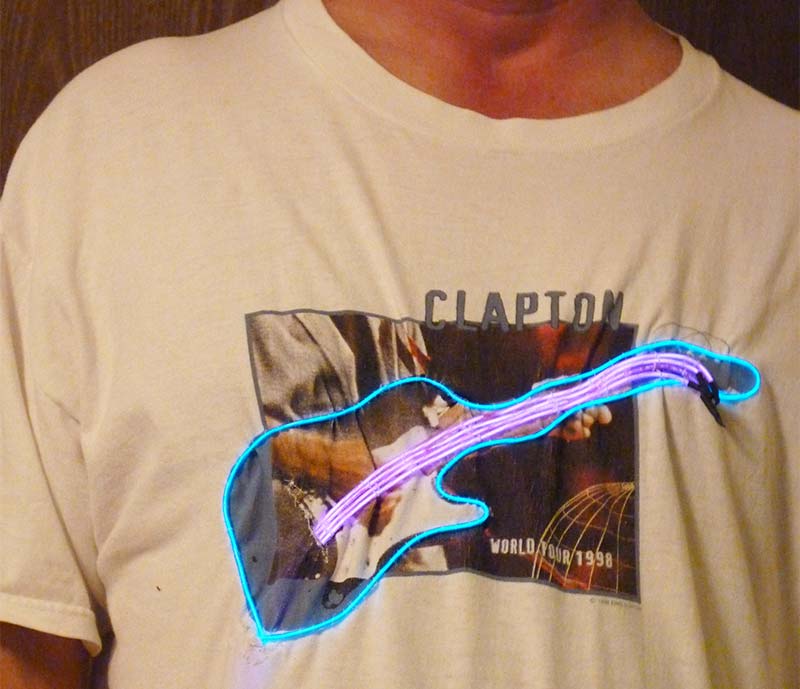
Photo 1.
There was just enough room on the neck of the guitar to allow four wires across. The body of the guitar was another circuit, for a total of five circuits. The PIC12F675 has six I/O pins. If I reserved one for a switch to change the pattern, I’d have five output pins. That left just connecting the controller to the shirt.
Looking around my parts bins, I spotted a spare Ethernet cable. Hmmm, eight wires. I checked the specs for the connectors, and they are rated for 120 volts AC at 1.5 amps. Five control lines, two grounds, and a spare. Perfect!
I now had all of my major components selected, so I started on the schematic (see Figure 1). I used ExpressSCH from ExpressPCB (www.expressPCB.com). I assigned each pin on the connector to a circuit. I assigned the spare pin to an “always on” circuit. Each of the controllable circuits led back to a G3 switch (U2-U7; note that I numbered them to match the pin they are attached to), then to the PIC pin. The pattern-changing switch is connected to pin 4 through a 1K ohm resistor. The pin is pulled high through R9 (10K) until you press the switch.
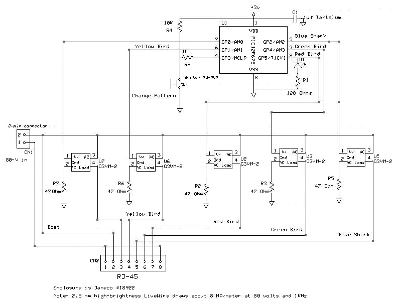
Figure 1.
Each G3 switch has a current-limiting resistor (R3-R7) to ground. They are also numbered to match the pin they are connected to. The G3 datasheet shows a typical current draw of 50 mA. Since I’m driving the PIC with three volts, the maximum I can expect on a “high” pin is about 2.7 volts. Plugging this into Ohm’s law gives 2.7V / 0.05 A = 54 ohms. A 1/8 watt 47-ohm resistor will do the job nicely.
Printed Circuit Board
I designed the printed circuit board (PCB) to fit into a Jameco 18922 enclosure. It’s 3.1” x 2” x .9” (inside), so I made the board 2.75” x 1.6” (see Figure 2). I ordered four of them from ExpressPCB. Note that you will have to cut off the corners of the board in order to clear the screw mounting bosses in each corner of the enclosure.
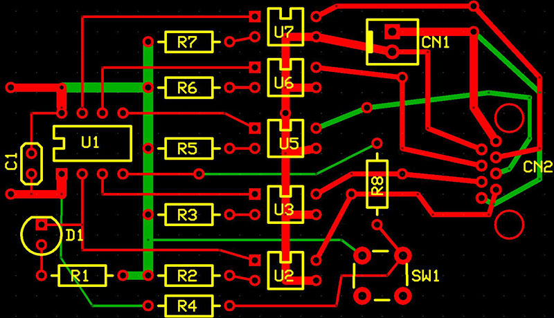
Figure 2.
From left to right, the PIC (U1) is at the end, the current-limiting resistors come next (R2-7), then the G3 switches (U2-7), the selection switch (SW1) and high voltage input connector (CN1), and finally the RJ-45 jack (CN2). There is an activity LED (D1) and current-limiting resistor (R1) in the lower left corner of the board, connected to pin 2. This helps you determine if the board is functioning.
Assembly
Assembly is very easy; all of the components are through-hole. Three volt power comes in the left side of the board from a 2xAAA battery holder attached to the inside of the enclosure cover with double-stick foam tape. There is a small switch glued to a 1/4” hole drilled in the cover which allows you to turn the controller on and off. Measured power draw with all circuits on is about 33 mA, so two AAA batteries rated at 1,125 mAh should last over 30 hours.
Start by soldering the shortest components in place — the resistors. Next, install the taller ones: the processor socket, the LED, and the G3 switches. I soldered the bypass cap (C1) to the bottom of the board to keep it out of the way when I was pulling and re-installing the processor during software development. After those components, install the pushbutton switch and the high voltage input plug. Notice I used just a simple two-pin plug. I soldered a two-pin socket I had lying around to the high voltage converter. This allows me to easily move it to another controller.
You may want to just directly solder the driver wire to the board. Even better, if you can find a source for the slick two-pin locking connectors on the inverters, you could have them plug directly into your board. In any case, tie a knot in the wire as a stress relief and notch the enclosure so that you can feed the wire through before you attach the lid (see Figure 3).
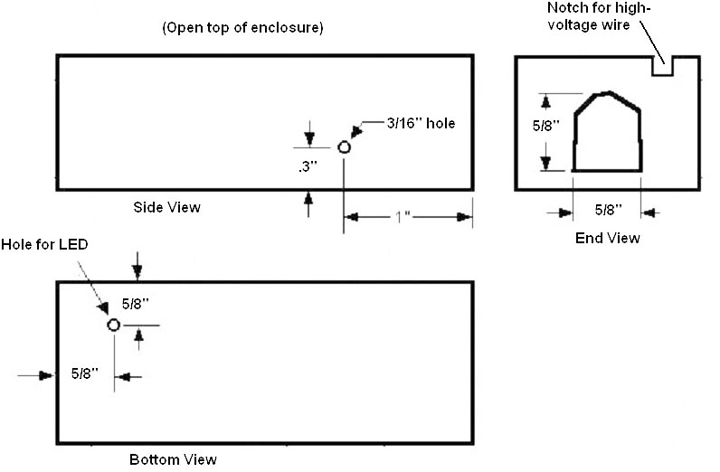
Figure 3.
The last component is the RJ-45 jack. Finally, connect the wires from the battery holder/switch. It should look like Photo 2. Notice that I put the activity LED on the top of the board. I’ve found that I tend to leave the controller on after using it, so I recommend that you install the LED on the bottom of the PCB and drill a hole in the bottom of the enclosure large enough for it to stick through. This gives you a visual indicator that the controller is on, without having to open the enclosure.
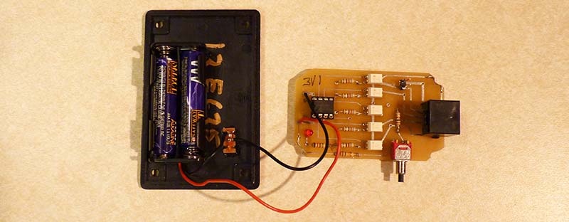
Photo 2.
Now, program a PIC12F675 with the program available in the downloads. I used a PICkit2, but there are many other options available. Do a web search for PIC programmers; you’ll find several. After programming, plug it into the socket on the board. Install the batteries and turn it on. The activity LED should light. If it doesn’t, check your battery connections and make sure that the PIC is oriented correctly. Press the pattern select button once or twice; the LED should start blinking.
Now, you need to prepare the enclosure. Drill a 3/16” hole in the side of the case to accommodate the pushbutton switch. Note the dimensions and location of the hole in Figure 3. You may want to make it a little oversized to make it easier to insert and remove the PCB. On the end of the enclosure, cut a hole for the RJ-45 plug to go through. I used a Dremel tool to make this opening. If you decide to install the LED on the bottom of the board, drill a hole to accommodate it. Please verify all dimensions before you drill!
The Shirt Design
This is actually the more difficult part of the design. You need to find a shirt with a simple, bold design that you can add light to. I started with the guitar T-shirt, but I’ve also used parrot T-shirts from Margaritaville.com (see Photo 3). The schematic is labeled for this shirt.

Photo 3A.

Photo 3B.
There is yellow wire on the yellow bird, red wire on the red bird, and green wire on the green bird. I used blue wire for the two shark fins. The blue wire is also connected to a shark fin on the front of the shirt (the birds are on the back). This helps me see if the shirt is working, since I can’t see the back very well. The always-on circuit is connected to white wire on the boat. The same circuit board and software is used for both shirts.
I used neon signs for inspiration; they have the same design limitations as EL wire. They have to be continuous strings and they can’t be bent too sharply. You will want to make as few splices in the EL wire as you can. Remember that you can link together different colors into the same circuit, either by connecting them to the same wire on the Ethernet cable or by daisy-chaining to the end of another EL wire. You'll need to sew a buttonhole in the shirt at each point the EL wire has to go through so that the shirt won’t fray. You will also want to cover the wire with shrink tubing anywhere it runs behind the shirt or it will show through when lit.
Figure out what sections should blink and in what patterns. Make careful notes about which processor pin you need to connect to what section of wire. Mark all of the EL wires with a piece of tape that shows which Ethernet wire it should connect to (blue, blue/white, etc.). This can save you many hours of debugging.
The EL Wire
Once you've firmed up your design, order enough EL wire. I usually buy 10 ft lengths of each color I want, along with a high powered inverter. You can also get the five-color CK-3 kit if you just need short pieces of several colors. For some designs, you may even be able to just lift the entire pre-made wire assembly and use it directly. If that’s not practical, you'll have to make your own wiring harness. The chart in Table 1 will help you keep track of each circuit.
| Ethernet Pin # |
Wire Color |
PIC Pin |
Bird Shirt |
Guitar |
| 1 |
Orange/White |
Ground |
Ground |
Ground |
| 2 |
Orange |
— |
Boat |
Body of Guitar |
| 3 |
Green/White |
7 |
— |
— |
| 4 |
Blue |
6 |
Yellow Bird |
String #1 |
| 5 |
Blue/White |
5 |
Blue Shark |
String #2 |
| 6 |
Green |
3 |
Green Bird |
String #3 |
| 7 |
Brown/White |
2 |
Red Bird |
String #4 |
| 8 |
Brown |
Ground |
Ground |
Ground |
Table 1.
The extremely fine wires inside the plastic insulation can be difficult to work with. I found a pair of high-powered reading glasses helped me locate them. For tips on soldering EL Wire, go to https://learn.adafruit.com/el-wire/soldering-to-el-wire. Make your connections sturdy; you may be crowd surfing with this shirt on! Use generous lengths of shrink tubing on all of your connections. I used 22-gauge speaker wire to connect the EL wire to the Ethernet cord.
First, separate the speaker wire for at least one inch. Cut one wire about 1/4” shorter than the other; strip them both for 1/4”. Next, strip about 3/8” of the colored jacket off the outside of the EL wire. Now, find the two very fine wires that spiral around the core inside the second clear layer. Very carefully strip off the second layer of insulation. Do not cut the wires! Fold them back out of the way. Scrape off 1/4” of the white layer covering the wire core. Put a piece of shrink tubing over the shorter speaker wire, and then solder that wire to the core of the EL wire.
Once it’s solidly connected, pull the shrink tubing over the connection up to the two fine wires and shrink it into place. I used 3/32” shrink tubing for all of my connections, but you might want to get some 1/8” to make the outer ones slide over the inner ones easier. Solder the two fine wires to the longer speaker wire. Check that the wire lights when you apply power. After you confirm that the connection is good, put some shrink tubing over the entire connection and shrink it into place.
After each EL wire had a lead wire and was attached to the shirt, I routed them all down to the bottom edge of the shirt and connected them to the Ethernet cable. Sew them all solidly in place. Make the Ethernet cable long enough to reach the pocket where you intend to keep the electronics. Leave some slack.
Once everything is connected, plug in the controller and turn on the EL inverter. Your always-on circuits should light up. Next, power up your controller and press the pattern switch once or twice. Your EL wire should start blinking. Once you are sure everything works, wrap all of the wires together with larger diameter shrink tubing.
Sewing
You may want to take your shirt to a local alterations shop for the button holes. It’s not easy to sew them into T-shirts. Don’t even consider doing them yourself without a sewing machine that does automatic buttonholes. If you do them yourself, you may want to get some self-adhesive liner material (called interfacing) at a fabric store. I’ve had mixed success with it. Sacrifice an old T-shirt to the cause and practice both with and without the interfacing.
Carefully mark where you need the holes to be with a light pencil mark or a pin. Allow the automatic buttonholer to do its job. Note which way the sewing machine makes the buttonhole outline — probably AWAY from you. Now, apply a generous-size patch of the interfacing behind the shirt and try again.
Select the method that works best on your fabric. You only need about a 4 mm hole for a single wire; a 6 or 7 mm hole will accommodate two wires. Once you are good at buttonholes, go ahead and sew them in your shirt. (Or, if you're lucky and know someone who can do them for you, all the better!) Take a good pair of scissors or a seam ripper and carefully open up the middle of each one.
Now, thread your first piece of EL wire through the buttonhole. Lay it out on the shirt exactly where it needs to go and tape or pin it down. Sew the wire in place firmly by hand; a sewing machine can’t do this job. Use heavy thread or a double strand of lighter thread. Be careful to not puncture the wire! Repeat for each strand of wire.
This is where it pays to know someone who can sew. Having an experienced hand help here is worth more than you can imagine. Use thread the same color as the shirt so that it blends in. I found that I needed a loop over the wire about every 1/2” in order to hold it securely in place. Put the loops closer around tight curves. The specs say you shouldn’t bend the EL wire any tighter than the radius of a dime, but I’ve made tighter corners and haven’t had any problems (yet). Tie every stitch firmly with a square knot. Double-knot them at high stress points (like where they go through the buttonholes). Don’t forget to put shrink tubing over EL wires routed behind the shirt so that they don’t show through.
The Software
If you’ve tested everything up to this point, all you have to do is turn it on; everything should work. However, you may want a different pattern than I used. That’s the whole point here. Be creative! The software is labeled for the three-bird T-shirt I made, but it will work just as well for a guitar design. Use the three birds and the shark for the guitar strings. I used the always-on circuit for the body of the guitar, but you could use pin 7 to blink it, too.
The code is all written in PIC assembly. It’s broken up into several subroutines that are called from the main loop. There’s a delay loop used for blinking that also checks the pattern selection switch. The processor runs off the 4 MHz internal clock; if you change this, you will have to adjust the delay code.
The switch code rotates an eight-bit variable called Direction” Whatever bit is on selects that pattern in the main loop. There are subroutines to blink each of the pins. Those are, in turn, called from subroutines that combine them into patterns.
Note that the one to blink pin 7 is not called since neither of these designs use it. BirdLoop2, for instance, blinks the guitar strings (or the three birds) in one direction or the other, depending on the value in Direction. The StayOn routine turns on all of the strings and waits for you to press the selection button (this is the default pattern when you turn it on). The BlinkOne routine will blink one of the strings, again based on the value in Direction.
I’ve just scratched the surface of what can be done with my code. You should customize it to go with the shirt design you come up with. There’s plenty of code space available, so if you feel like programming the cords for “Stairway to Heaven,” go for it. Have fun! NV
Parts List
| QTY |
DESCRIPTION |
ID |
SOURCE AND PART# |
| 5 |
47 ohm, 1/8 watt resistor |
R2-R4, R5-R7 |
Digi-Key CF18JT47R0TR-ND |
| 1 |
1K ohm, 1/8 watt resistor |
R8 |
Digi-Key RNF18FTD1K00CT-ND |
| 1 |
10K ohm, 1/8 watt resistor |
R4 |
Digi-Key RNF18FTD10K0CT-ND |
| 1 |
120 ohm, 1/8 watt resistor |
R1 |
Digi-Key CF18JT120RCT-ND |
| 1 |
Pushbutton switch, NO |
SW1 |
Jameco 71643-2 |
| 1 |
.1 µF capacitor |
C1 |
Jameco 15270 |
| 1 |
LED, any color |
D1 |
|
| 1 |
Eight-pin DIP socket |
|
Digi-Key ED2202-ND |
| 1 |
PIC12F675 processor |
U1 |
Digi-Key PIC12F675-I/P-ND / Jameco 223781 |
| 1 |
RJ-45 socket |
CN2 |
Digi-Key WM5432-ND |
| 5 |
G3VM-2L opto-isolated relay |
U2-U3, U4-U7 |
Digi-Key Z2710-ND (note new “L” version) |
| 1 |
Enclosure |
|
Jameco 18922 |
| 1 |
Slide power switch |
|
Jameco 109171-3 |
| 1 |
Two “AAA” battery holder |
|
Jameco 616283-3 |
| 10 ft |
3/32” shrink tubing |
|
Jameco 644834 |
| 1 roll |
24-gauge speaker wire |
|
Jameco 100280 |
| 1 |
Ethernet patch cord |
|
Jameco 2115602 |
| 1 |
Two-pin .1” C-C header |
CN1 |
Jameco 108338 |
| 1 |
Two-pin socket |
|
Taken from old computer case |