I’ve been married for almost 70 years now, so finding my wife a Christmas present becomes more of a challenge. It’s not like I can't afford to go to the store and buy something. It’s just that I was raised believing that a gift should come from the heart and be something handmade. I'll never forget when I was eight, my dad made me a plyboard jeep with a 30 caliber machine gun mounted in the back that was made out of a cardboard shipping tube.
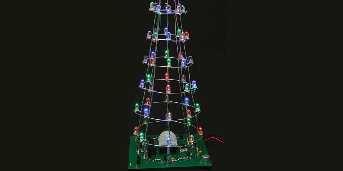
Due to allergies in the family, we can’t have a live Christmas tree, and I’m getting too old to put up a fake one. My grandkids are all older too, so now I’m waiting for great-grandkids. Thumbing back through some old issues of Nuts & Volts, I came upon an issue that had a Christmas tree made out of LEDs. Searching the Internet, I found several methods for making a cone shape tree utilizing different techniques. While there are a plethora of kits available, I decided to come up with my own (Figure 1).
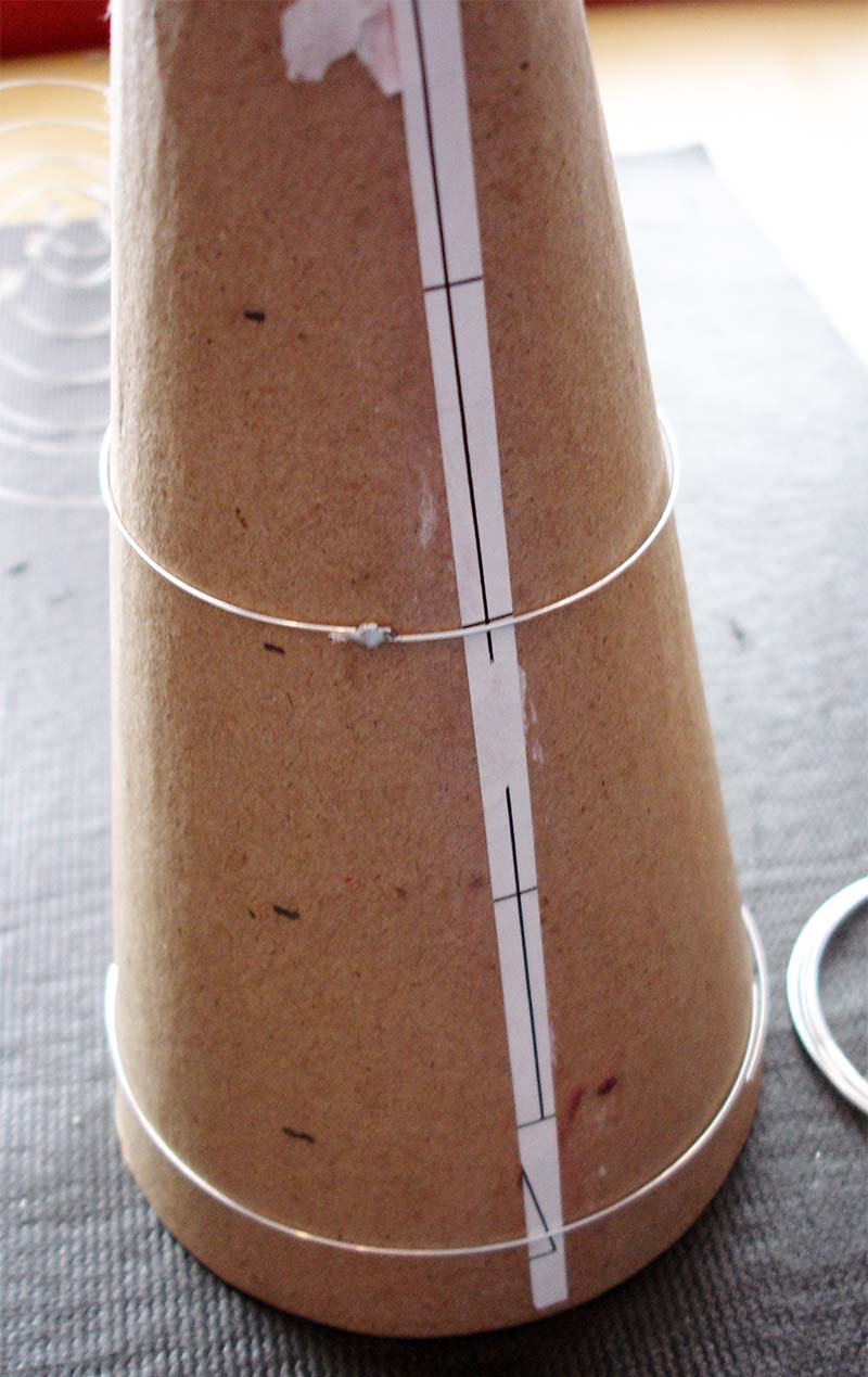
Figure 1.
I added a pryoelectric infrared (PIR) sensor for a proximity detector, along with a microphone circuit which detects music and then flashes accordingly to the beat.
The tree has a four inch square base and a height of 10.5”. There are eight columns which have 56 LEDs. The top LED is a tri-colored unit that changes colors. The LEDs are multiplexed to save power, and appear to be on all the time even though they’re not.
Let me digress. In 1948, Southern California Edison switched from 50 Hz to 60 Hz. I remember this well as all the electric clocks had to be discarded, along with many motors. Using 50 Hz and incandescent bulbs, no one could see the flicker since the filament could not cool off that fast. Keep in mind that when using a 50 Hz alternating current, there is a period of time (100 times per second/zero crossing) when the power is off. However, in 1938 when fluorescent bulbs became popular, a noticeable flicker could be observed that drove people nuts.
The human eye experiences a phenomenon known as Persistence of Vision (POV). What this amounts to is that above certain frequencies, the eyes retain an image. Electronics have used this for years to save energy. Its standard use is with seven-segment displays. You have three digits with a seven-segment display (eight, if you use the decimal). If you were going to use a gate for each segment, you would need a microprocessor with gates of 3 x 7, or 21 gates. In this project, we have 59 LEDs so we need 59 gates — a very large microprocessor indeed.
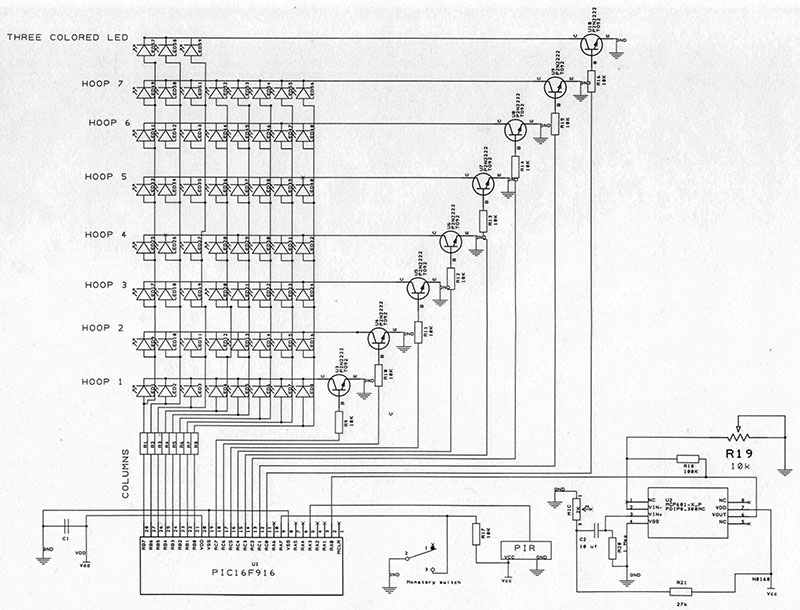
SCHEMATIC. A full size schematic file is available in the downloads.
If we put eight LEDs anodes to eight gates and connect all the cathodes to a switch, we can control the eight LEDs to be on or off via the switch. Now, if you connect another eight LEDs and connect their anodes to the same gates, then add another switch to their cathodes, we can control 16 LEDs by turning off and on their cathodes and gates.
Continuing on for six more strings, we can control 64 LEDs with 16 gates: 16/2 = 8; 8x8 = 64. Another way to look at it is we are using binary with two conditions: either on or off — 28 = 64. The microprocessor used is running at a rate of 4 MHz, so turning 64 LEDs on and off is no problem. In fact, we have to add time delays to see them pulse (or have that annoying flicker).
With this project, I decided to put a four-terminal LED for the last LED and only use seven layers of eight LEDs, or 56 + 1 (three colored) = 57 LEDs. The remaining five positions will remain empty. By strobing at a rate greater than 60, the LEDs will seem to stay on to the eye. This is taken care of in software, and saves power and microprocessor space.
THE PCB
The printed circuit board (PCB) was designed using ExpressPCB’s free software at www.expresspcb.com. The board files are available in the downloads, along with the microprocessor programming files.
All of the components go on the top of the board. Solder IC1 socket and IC2 to the board. Note that the pin 1 location is the square pad. Bend the leads of eight 220 ohm resistors and place them into R1-R8. Bend the leads of nine 10K resistors and place them into their respective holes in R9-R17. Place a 100K into R18, 27K into R20, and a one megohm into R21. Solder all the resistors.
Solder R19 which is the pot. Solder C1; it has no polarity. Solder C2; it does have polarity. Put the long LED into the + pad. Hold the microphone so it’s facing its pins, and rotate it so the pins are at the top. Pin 1 is to the left and is positive. Solder the microphone. Solder the two switches and transistors, noting their outlines on the board.
Run the two battery wires from the battery holder through the strain hole below C1; solder the black wire to “B” and the red one to “R.”
Mount the battery pack to the bottom of the board using double-sided tape or just put it to the side. (If you put the battery holder to the side, add four rubber feet.)
PIR MODULE MOUNTING
Turn the PIR module over so that the pots are on the top of the board. To the upper right are three pads: one with an “L;” one unmarked; and the other with an “H.” Take a razor blade and cut the trace to the center pad and the H pad. Using a small wire, short the L and the center pad. This will cause the PIR to fire every second when there is a body present triggering the tree.
On the PIR board, there are three pins: “GND,” “OUT,“ and “VCC.” Solder three wire-wrap wires to these pins and strip the insulation off of each one. Thread the three wires into the main board. Place the two 2-56 3/4” screws through the bottom of the board and add the two spacers. Thread the screws into the PIR board. They should self-thread. Solder the three wires (Figure 2).
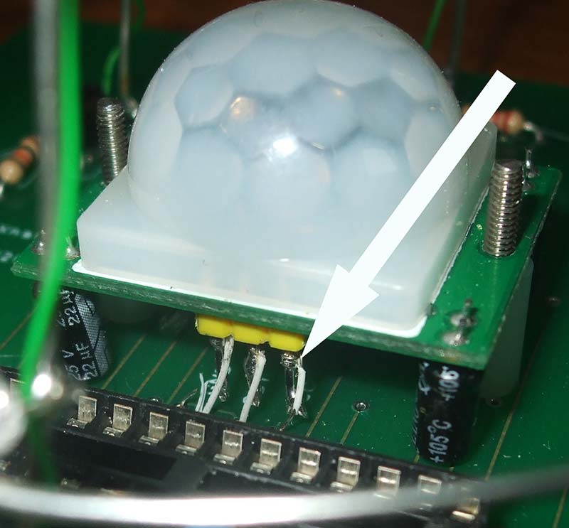
Figure 2.
MAKING CHRISTMAS HULA HOOPS
The hoops of the tree are made out of 18 gauge bus wire, which is quite malleable. Get the hoop template in the downloads. Cut the bus wires to the ring sizes under the template. Bend the bus wire to fit (Figure 3).
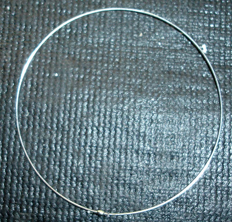
Figure 3.
Butt the ends of the wire together and solder. I’m a firm believer in using “tacky flux” by Quick Chip© and always have a syringe around for both soldering and de-soldering. Massage the wires so they are flat and round. There are seven hoops; do the same for the rest.
With each hoop, place the butted ends between the spokes. Place a drop of solder on each spoke crossing. At first I tried using a Sharpie©, but it makes a big black mess with the tacky flux on the LEDs.
Cut eight bus wires to a length of 10”. Using two pairs of pliers, pull the wires taut and run them over a sharp edge (of a table, for example) to straighten them.
MOUNTING THE LEDS
I found it best to mount the 10” wire on a ruler with two pieces of tape at the ends; refer to Figure 4.
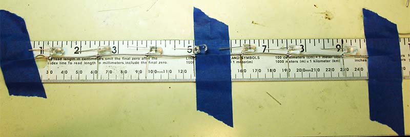
Figure 4.
If you are using colored LEDs, download the LED matrix file. The microprocessor is programmed to the color pattern on this matrix. (I used one of wife’s muffin pans to put the LEDs in so they didn’t get mixed up.)
Bend the long anode lead of the green LED out at a right angle. Slide it under the column wire with the LED pointing to the right. Solder the anode to the wire so there is about 1/16” between the LED and the wire at position 1 (which is 1-1/4” from the end of the wire).
Using the matrix, go DOWN the column for the next colored LED, which will be blue, then yellow, then red. Space each LED at 1.25” (e.g., 1.25”, 2.5”, 3.75”, 4”, 5.25”, 6.5”, 7.75”, 9”). Cut off the excess anodes, and put a piece of tape on the finished column with the #1 on it (Figure 5).
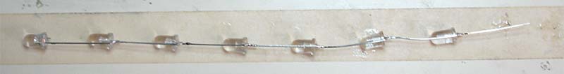
Figure 5.
Do the same for the next wire, noting that the first LED is blue; label it #2. Do the same for the remaining six columns.
Put column 1 into a vice with the LED pointing up. Place the first ring with its first mark on the cathode and bend the cathode up to hold the ring. Solder the cathode to the ring. Continue for each ring until all of them are soldered.
Locate column 5 and mount it in the vice with the LEDs pointing upward. Locate spoke 5 on the rings, which will be 180 degrees from column 1. Thread the column through the rings and solder the LEDs to the ring. This procedure will give structure and will make it easier to keep the form and symmetry of the cone (Figure 6).
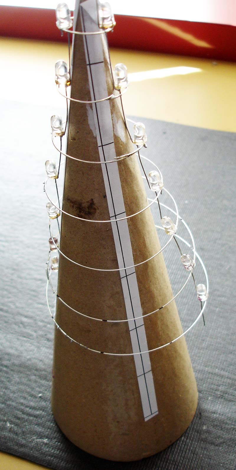
Figure 6.
Going clockwise from column 1 (looking from the top), solder column 3 and column 7, then column 2 and 6, and finally columns 4 and 8. Re-solder any LEDs that are out of alignment.
THREE-COLORED LED
Cut the top wires off of columns 4, 5, 6, 7, and 8 to their last LED. You should now have three wires from the top of the cone. Cut an 11” green wire-wrap wire, wire wrap it to the long LED lead (cathode), and solder. You may have to cut it shorter so that the wire is next to the LED. Going left to right, lead 1 is green, 2 is blue, 3 is the cathode, and lead 4 is red.
Solder lead 1 from the LED to column 1 so that the three-colored LED is in the center of the cone as the last layer of LEDs. Solder LED 2 to column 2 and lead 4 to column 3. Cut the excess wires off.
Take the green wire from the cathode of the three-colored LED and wrap one turn between each LED on column 8. Leave about 1” below the column wire for soldering to the board.
Locate column 1 and solder a green wire to ring 1, then wrap one turn around column 1 with 1” below the column. Using column 2/ring 2, solder a green wire. Continue to ring 7, wrapping one turn around the columns between the LEDs. Refer to Figure 7.
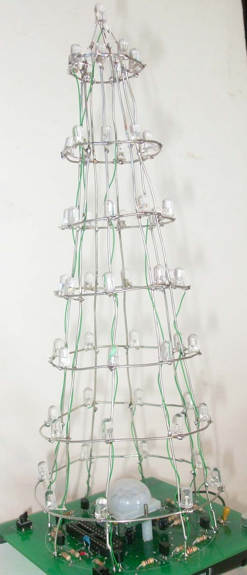
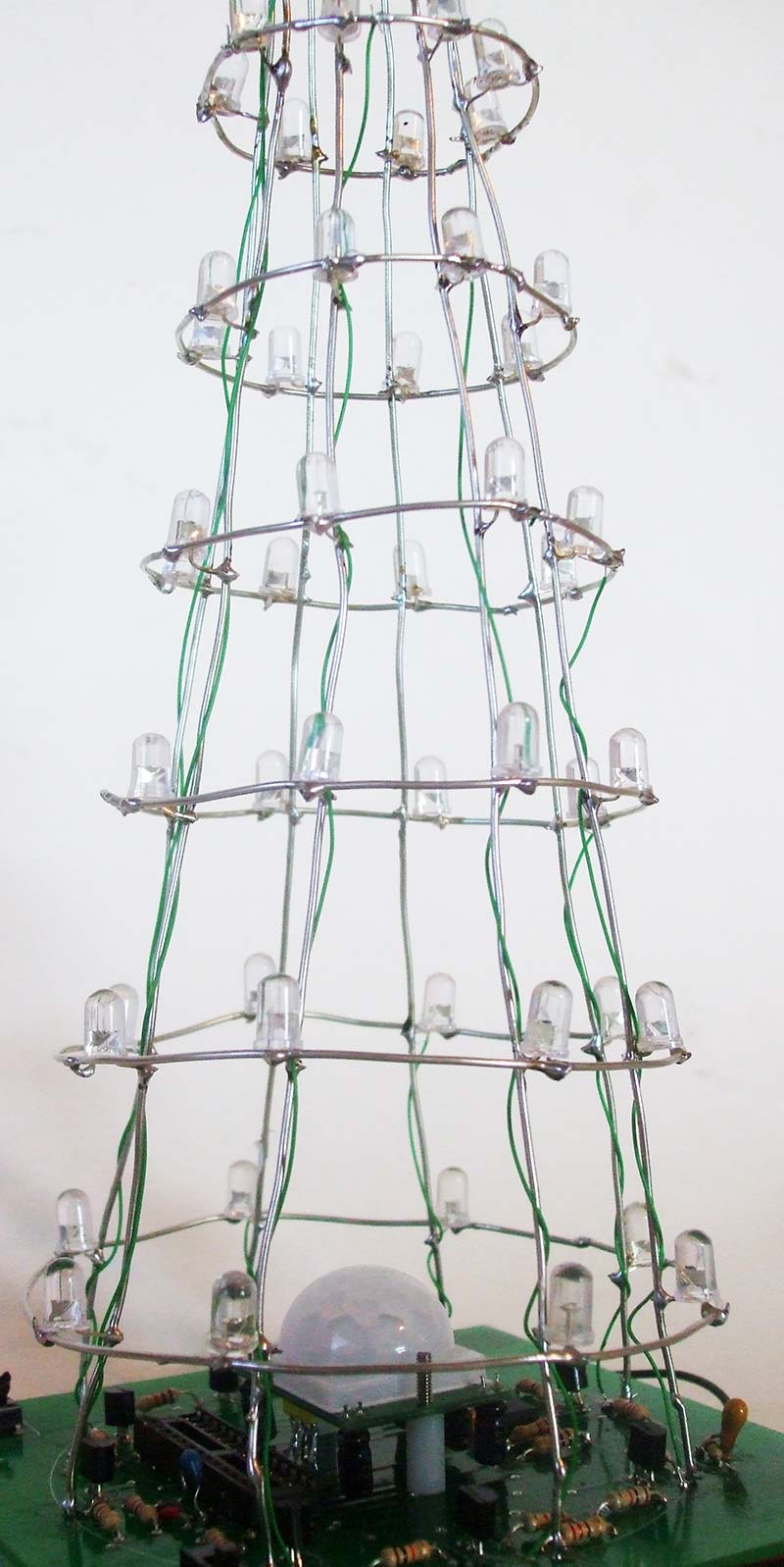
Figure 7.
MOUNTING THE TREE
Starting with column 1 (the nine o’ clock position) and going clockwise, push the columns through their respective holes. Make sure that the tree is vertical and not looking like the “Leaning Tower of Pisa.” Solder the columns, then solder the wire-wrap wires to the hole labeled “W.” Push the columns into their holes which are numbered. Again, make sure the columns are straight. Solder all the columns. Place the wire-wrap wires into their holes next to the column holes marked W and solder. Trim off any excess wires so it looks like Figure 8.
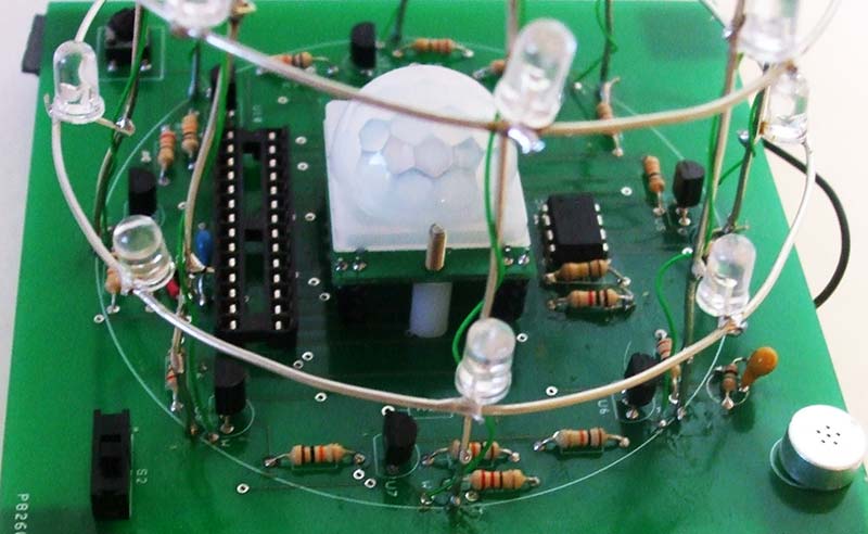
Figure 8.
USING THE TREE
Put in three AA batteries, noting their polarity. Turn on the slide switch. The tree should light up, giving many different patterns. There are actually four different modes that can be changed. If you just turn the unit on, it will continuously run until turned off. Hold down the momentary switch while turning on the power. Then, when the switch is released, the top LED will turn blue, indicating that you are in microphone mode.
By pushing the momentary switch again, the top LED will turn green, indicating you are in the PIR mode. Push the switch again, and the top LED will turn red; all the LEDs will remain lit. There is a built-in 2-3 second delay that allows you to change settings. Keep in mind there may be slight delays due to the capacitor charging before the PIR and microphone start working.
PIR
(GREEN LED)
When the PIR module detects a change such as body heat, the tree will light for a period of time, then shut off. It will continue to cycle if there is any movement.
There are two adjustments on the PIR module. When mounted (viewing from the back), turn the left pot all the way counter-clockwise. This is a delay which holds the pulse high for a period of time. Turn the right pot all the way clockwise. This is the sensitivity. There is a 2-4 second delay before the PIR will trigger.
MUSIC BEAT
(BLUE LED)
Place the tree next to a speaker or on top of one. The light will change color when sounds are detected. You can also clap to activate the microphone. The sensitivity can be changed by varying R19; going counter-clockwise will increase the sensitivity.
ALL ON
(RED LED)
The LEDs are being multiplexed and appear to be on all the time (even though they’re not).
HOW IT WORKS
The columns (anodes) are driven by port B of the microcontroller; the ports can sink or source up to 35 milliamps. Port C connects each of its ports to eight NPN transistors via 10K resistors, which pull the LED cathodes to ground. A positive voltage on the NPN transistor will cause it to conduct.
The patterns are generated by the microprocessor mainly by rotating the bits of ports B and C right or left, and turning the LEDs on and off for short periods of time. The assembly files are available at the article link for those interested. I have added a socket so you can create your own programs and experiment around if you’d like.
The PIR and microphone are directed to the interrupt vectors of the microprocessor. The microphone is amplified 100 times by an operational amplifier (U2), and when a voltage pulse is detected the microprocessor jumps to the random generator. In the interrupt mode, the microprocessor is put to sleep to save power.
Have a Merry Christmas and be the LED of someone’s life! NV
| Item |
Description |
Model |
Qty |
Souce |
| BH |
Battery holder 3 AA |
534-2465 |
1 |
Mouser |
| C1 |
.1 µF |
|
1 |
|
| C2 |
10 µF |
|
1 |
|
| IC1 |
Proximity sensor |
|
1 |
RobotShop |
| Mic |
Microphone |
665-AOM4546PNFR |
1 |
Mouser |
| LED 1 |
Red |
859-LTL353QRKNN |
14 |
Mouser |
| LED 2 |
Amber |
|
14 |
Jameco |
| LED 3 |
Green |
859-LTL3H3TGUADS1 |
14 |
Mouser |
| LED 4 |
Blue |
859-LTL2P3TBU2KS |
14 |
Mouser |
| LED 5 |
Multicolored common cathode |
RL5-RGB-DCC |
1 |
SuperBrightLEDs |
| R1-R8 |
220 ohm 1/4 watt |
291-220-RC |
8 |
Mouser |
| R9-R17 |
10K 1/4 watt |
291-10K-RC |
9 |
Mouser |
| R18 |
100K 1/4 watt |
291-100K-RC |
1 |
Mouser |
| R19 |
10 pot |
|
1 |
|
| R20 |
1 meg 1/4 watt |
291-1M-RC |
1 |
Mouser |
| R21 |
27K 1/4 watt |
291-27K-RC |
1 |
Mouser |
| Screws |
2-56 x 3/4" |
|
2 |
|
| Socked |
Socket 28-pin |
526248 |
1 |
Jameco |
| Standoffs |
3/8" 2-56 |
|
2 |
|
| SW1 |
On-Off |
612-EG1218 |
1 |
Mouser |
| SW2 |
Momentary switch |
612-TL1105-250 |
1 |
Mouser |
| U1 |
PIC16F916 |
|
1 |
Newark |
| U2 |
Op-amp |
579-MCP601-E/SN |
1 |
Mouser |
| U3-U10 |
NPN transistor |
|
8 |
Jameco |
| Wire |
18 bus |
|
|
Jameco |
| Wire |
Green wire wrap |
22606, 10' |
|
Jameco |
Downloads
ASM files, Template, Instructions, PCB file, Hints and Tips doc.