We have all seen it so many times. Our hero returns to his (or her) room to find a hair fallen from the door sill. Out comes the Walther PPK! That hair, placed on the door sill before breakfast at a sunny sidewalk café, saves our hero. It functioned as a physical memory of the status of the door. The hair detected the occurrence or non-occurrence of a specific event and stored that information for retrieval by the spy returning to the room. This hair-based non-volatile memory had only two possible states that could be instantly read by the controller (our hero): in position (no event occurred) or not in position (the event occurred). Programming the hair meant placing it at a specific position on the door sill to be held in place by the door. If the door was opened during the retention period (breakfast), gravity let the hair fall from its pre-set position. No battery was needed for this event detector!
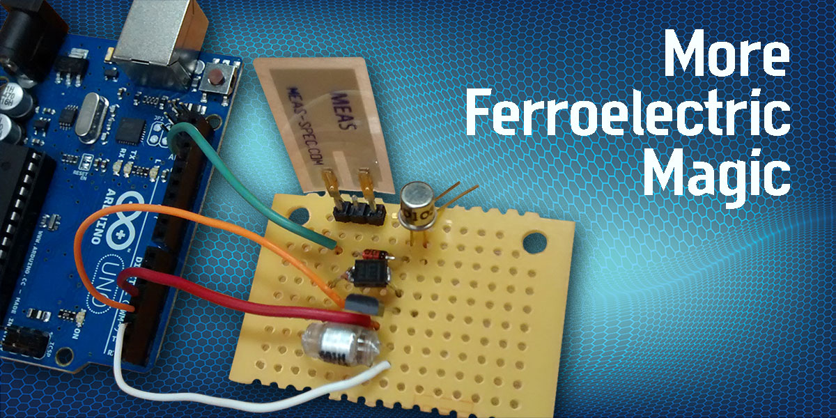
More Ferroelectric Magic
Ferroelectric capacitors make it possible to create an electronic version of the hair-based non-volatile event detector. Unlike more delicate forms of non-volatile memory that depend on static charges buried deep inside silicon dioxide, ferroelectric capacitors can operate in the natural world without being destroyed by Mother Nature’s penchant for lightening large and small.
Nuts & Volts featured an extensive article describing the physics of ferroelectric capacitors used as memory elements. Demonstrated in the article was a method of building and operating a simple non-volatile memory using a ferroelectric capacitor, a microprocessor, and a linear sense capacitor. In this article, we will show how to add a few more external components to that same memory bit to allow it to detect events and report them later.
Review of Ferroelectric Memory
Following is a quick review of ferroelectricity. For a more complete description, please re-read the original article. The crystal lattice of a ferroelectric capacitor is naturally polarized in the same way that a permanent magnet is permanently magnetized. This internal electric polarization cannot be detected with a voltmeter because the capacitor plates will always collect enough of the opposite charges to exactly cancel the polarization.
The internal polarization can be forced to change its direction by moving the cancellation charge from one capacitor plate to the opposite plate. We read the state of the capacitor by monitoring the current flow that erupts from the capacitor when a reference voltage is applied to the capacitor. The stored datum corresponds to the direction of that internal polarization.
The plot in Figure 1 shows two single-cycle hysteresis loops in terms of absolute charge for a ferroelectric capacitor starting from opposite dipole orientations.
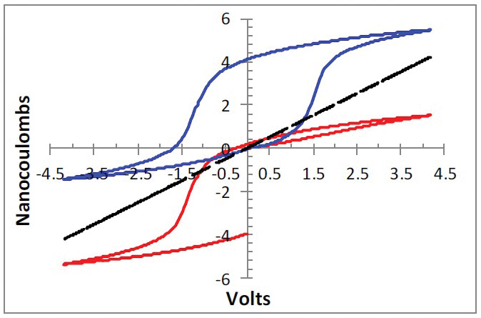
FIGURE 1. UP and DOWN state full-cycle ferroelectric hysteresis loops compared to an equivalent-sized linear capacitor.
The horizontal axis is the voltage applied across the ferroelectric capacitor. The vertical axis is the count of the charges that come from the capacitor during actuation. A linear capacitor is also plotted for reference.
How much charge comes out of the capacitor when a positive voltage is applied tells us in which direction the ferroelectric capacitor pointed prior to the read operation. A linear capacitor in series with a ferroelectric capacitor can sense and report the amount of charge moving in Figure 1. We attach this capacitor stack to two I/O pins of a microprocessor to create a single bit of non-volatile memory.
The linear capacitor must be sized so if the ferroelectric capacitor does not switch during a read operation, the small amount of charge that comes out of the ferroelectric capacitor into the linear capacitor cannot generate enough voltage on the common I/O pin to be read as a 1. If the ferroelectric capacitor does switch, so much more charge goes into the linear capacitor that its voltage on the I/O pin is read as a 1 by the microprocessor.
Figure 2 redraws the ferroelectric hysteresis loops of Figure 1 in terms of charge delivered at the top of the read voltage application.
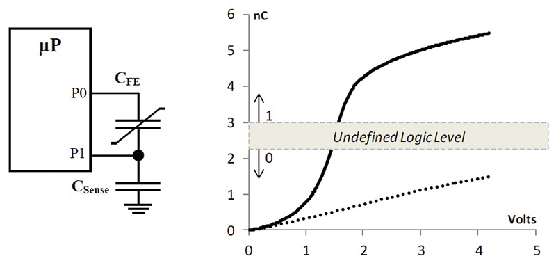
FIGURE 2. Microprocessor-based non-volatile ferroelectric memory and a plot of its UP/DOWN memory states during a read operation.
Event Detection
The Type AD ferroelectric capacitor used in the February article to demonstrate the memory circuit of Figure 2 required six nanocoulombs of charge to be delivered within 4.2 volts. (Refer to the vertical axis of Figure 2.) Any sensor or generator that can source that energy can fully switch that ferroelectric capacitor. Attaching such a sensor to the ferroelectric capacitor in Figure 2 creates an event detector. The microprocessor presets the ferroelectric capacitor in one direction and turns itself off. The sensor — if activated — moves the ferroelectric capacitor to the opposite direction. Upon waking up, the microprocessor executes a read operation. Was the ferroelectric bit in its original state or did it change?
There are a variety of readily-available sensors that can set the state of the Type AD capacitor. A solar cell can detect the presence of light in a room. A toy-scale electric motor will generate energy when its axle is turned by rolling motion. An antenna loop tuned to 13.56 MHz can be activated by the Near Field Communication (NFC) smart tag antenna in your cell phone to provide enough energy to switch a ferroelectric capacitor.
For this project, we will use the LTD0-028K piezoelectric flapper manufactured by Measurement Specialties, Inc. The LDT0-028K is labeled as a vibration sensor or as a piezoelectric switch. It consists of Polyvinylidene Fluoride (PVDF) — a piezoelectric plastic with metallic electrodes. If its plastic tab is bent over 90 degrees, the LTD0-028K will generate up to 7 nC of charge, or 90 volts. In Figure 3, we use a plastic piezoelectric capacitor to switch a ceramic ferroelectric capacitor in an event detector circuit.
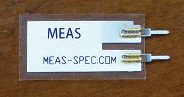
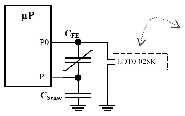
FIGURE 3. Simple event detector circuit and the LTD0-028K sensor.
There are issues using the LDT-028K bender as shown in Figure 3. It is a capacitor, so when sharing charge with the Type AD ferroelectric capacitor, it will generate the voltage set by the ferroelectric capacitor for the amount of charge being deposited. If the ferroelectric capacitor starts DOWN, a bend of the plastic piezoelectric switch generates 7 nC to force the capacitor UP. According to Figure 2, the voltage will only reach about six volts.
However, if the ferroelectric capacitor is already UP and does not switch, the switch could generate a far higher voltage across the ferroelectric capacitor and damage it. Even more important, if the plastic piezoelectric switch is bent the wrong way, it will generate negative voltages!
Another issue with the simple circuit in Figure 3 is the status of P0 and P1 when the microprocessor is powered down. All pins on a microprocessor package will have clamping diodes to the power rails (Vcc and ground) to dissipate static discharge inadvertently applied to a pin. When the LDT0-028K attempts to generate a voltage on P0 to switch the ferroelectric capacitor UP while the microprocessor is powered off, the clamping diodes on P0 will limit the voltage range to ±0.7 volts.
A blocking transistor must be placed on P0 to isolate the external components from the clamping diodes of P0 inside the package when the microprocessor is turned off. On the other hand, we can use this property to our advantage on P1. When the piezoelectric switch attempts to change the state of the ferroelectric capacitor and the microprocessor is off, the ferroelectric charge will flow into CSense until the voltage on CSense exceeds the clamping voltage on P1; whereupon, the excess current will flow to ground. We will not have to worry about back voltage from CSense fighting the voltage across the ferroelectric capacitor applied by the switch. To solve these issues, we add three components to the event detector circuit in Figure 3 to create a realistic real world circuit in Figure 4.
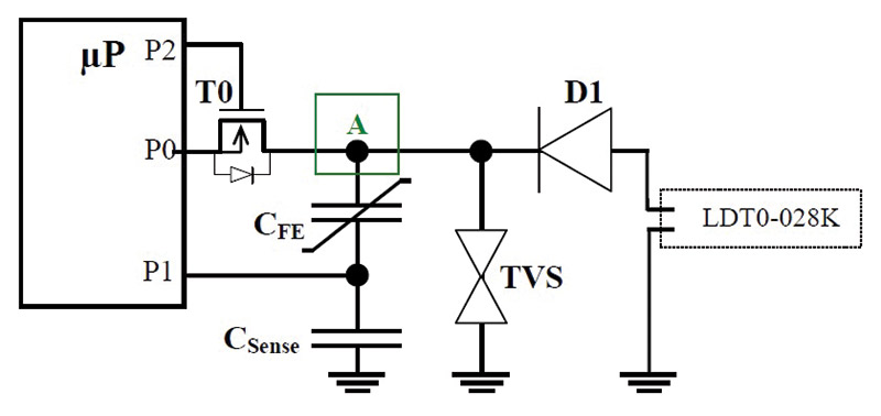
FIGURE 4. An event detector circuit complete with overvoltage protection.
T0 isolates the common node A from P0 and is only enabled by the microprocessor when it wants to write or read CFE. When power is off to the microprocessor, T0 will be off to allow the piezoelectric switch (LDT0-028K) to generate a voltage across the ferroelectric capacitor and not be clamped to ground by P0. When power is on, event detection will still function.
T0 is turned off during detection. P0 and P1 are left at zero volts. Sensing pulses from the LDT0-028K are blocked from P0 by T0, but current from CFE can flow into P1. D1 — at all times — blocks negative voltages from the sensor, and the TVS limits the voltage across the ferroelectric capacitor to no more than +6 volts.
Recommended components for the detector are:
- Radiant Technologies Type AD 10,000 µm2 ferroelectric capacitor
- 680 pF CSense
- 2N7002 N-channel FET for T0
- SMAJ-6.0A for the TVS
- 1N914 for D1
Our prototype of the circuit appears in Figure 5.
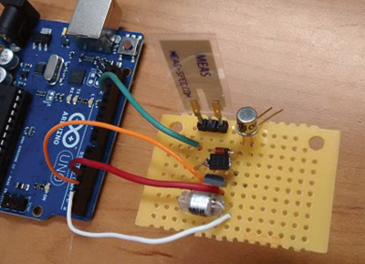
FIGURE 5. An event detector circuit on a perfboard.
The piezoelectric flapper is mounted directly on the board in Figure 5 for debug purposes. Later, it can be mounted to a door so that its tab will be bent by the door when the door is opened. The sensor is connected to the circuit board using twisted pair.
Note that a voltage limit to CFE is introduced by T0. P2 will activate the gate of T0 to turn it on. As CFE charges up during a read operation, it will stop 0.7 volts below the gate voltage. This will not be a problem in our recommended circuit as the Arduino Uno I/O pins operate at five volts and the Type AD capacitor saturates at 2.1 volts. It does become a problem for thicker ferroelectric capacitors like the Type AB. The voltage drop across the transistor disappears when CFE is being written down by P1, while P0 is ground.
Programming
The program to operate the event detector from the Arduino is similar to that explained in the February article, but more automatic. Only one routine is needed. The routine always executes a read followed by a write DOWN to reset the event detector for the next detection period:
1. Set P2 high to turn on T0.
2. Leave P1 as an input to detect the voltage across CSense.
3. Set P0 high.
4. Read the digital state of P1.
a. If CF = DOWN, P1 will show Logic 1 indicating that no event occurred.
b. If CF = UP, P1 will show Logic 0 indicating that the event occurred.
5. Set P0 low. CFE and CSense will both be at zero volts.
6. Set P1 high to write CFE DOWN to prepare for the next detection period.
7. Set P1 low. CFE and CSense will again both be at zero volts.
8. Set P2 low to turn off T0 and isolate P1.
The next power-on detection period now starts. If power is to be turned off, first set both P0 and P1 as inputs to ensure no voltage spikes are applied to CFE during power-down when the logic inside the Arduino goes unstable as voltage drops below the minimum specification.
The Arduino can be set up to execute the read-reset routine from one of three situations:
- Subroutine call from a master program.
- Upon reset by the reset button on the Uno.
- Upon power-up.
The program to operate the Uno and the event detector is located at the article link. The program turns on the LED on the Arduino board attached to pin 13 to indicate if an event occurred.
The Event Detector in Operation
It is important to remember when mounting the LDT0-028K flapper on the door that it can generate either a positive or negative voltage. The direction can be determined with an oscilloscope connected to the event detector circuit at point A.
An activation of the LTD0-028K flapper causes the voltage spike across CFE shown as the top trace in Figure 6.
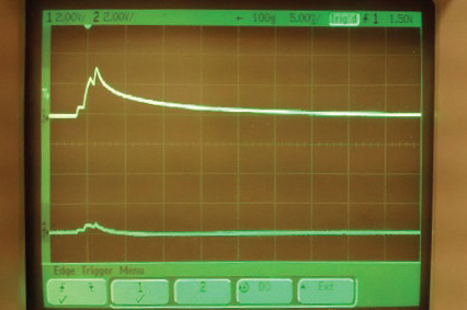
FIGURE 6. Voltage generated across CFE (top trace) by the piezoelectric flapper, bent 90 degrees.
The vertical scale is two volts per grid line. Figure 7 captures the voltages at A and P1 during the read-reset operation for no-event (left) and event (right).
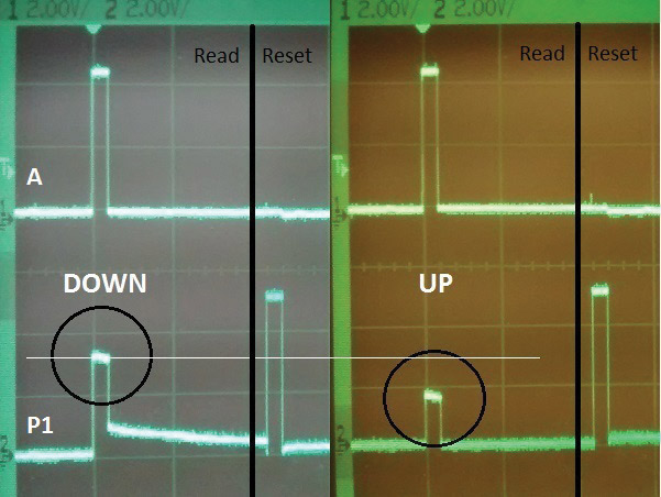
FIGURE 7. Oscilloscope traces for event and no-event read-reset operations on the event detector.
To capture the traces, the read-reset routine was executed twice. The first execution preset CFE DOWN. The outcome of its read operation was ignored.
The second execution determined if we had activated the piezoelectric flapper or not since the first execution.
The bottom trace in Figure 7 shows the sense voltage on P1. If no event occurs, CFE is still DOWN when the capacitor state is read. The ferroelectric switching charge will generate over three volts on the P1 pin from the charge in CSense. This voltage will be read as Logic 1 by the Arduino.
If the event occurred during the detection period, no ferroelectric switching will take place during the read operation; less charge will flow from CFE to CSense; less than two volts will be generated on the input P1. This state will read as Logic 0 by the Arduino.
Conclusion
The ferroelectric event detector adds excitement to a single bit of non-volatile memory: An outside sensor performs the write operation so the microprocessor can detect the occurrence of events in its local environment. The event detector will remember the event after it occurs so the controller can be powered off while it waits. NV
Resources
Tester website
www.ferrodevices.com
Vendor website for the microprocessors
http://arduino.cc
Measurement Specialties, Inc.
http://meas-spec.com
Downloads
Source Codes and Data Plots