For some time, I had been searching for a way to add FM reception to one of my All American Five (AA5) tube-type radios. I came across projects that “gutted” the original AM radio replacing the inside with a FM receiver. I rejected this approach as I wanted to maintain my radio’s AM receiver capability.
Given an FM audio source, I could handle audio selection and volume control with a switch inserted before the radio’s volume control. The problem was how to use the existing tuning control and dial to select stations in FM mode.
The solution came to me while reading Peter Wright’s non-fiction book, “Spy Catcher — The Candid Autobiography of a Senior Intelligence Officer.” Wright was a key figure in British intelligence serving as a science specialist from 1955 to 1980. Wright’s father was Director of Research for radio pioneer, Guglielmo Marconi. From an early age, Wright was exposed to radio theory and practice, which was to prove key to much of his success in the intelligence service.
In 1955, when Wright began his career with MI5, the Cold War between the West and Soviet Russia was heating up. With suspicions running high, MI5 operated a corps of agents called Watchers who followed Russian diplomats and possible agents as they moved about London. MI5 suspected that surveillance information collected by the Watchers was getting back to the Soviets and affecting their operation.
One possibility was that Soviet agents inside the Soviet Embassy were monitoring Watcher two-way radio communication back to MI5 headquarters. Wright came up with a clever plan to prove this was the source of the leak.
Superheterodyne radios used at that time contained a local oscillator to convert the incoming signal to an intermediate frequency for amplification. Through lack of shielding, the local oscillator acted as a low power transmitter that could be picked up as much as two hundred yards from the receiver. Wright’s idea was to equip a vehicle with a very sensitive receiver that could pick up this “leakage” signal and, knowing its frequency, prove that the Soviets were listening in to Watcher transmissions. The operation was code-named RAFTER.
While the mobile unit was being outfitted, Wright researched the types of radios in the Soviet Embassy so he could calculate the “leaked” frequencies MI5 agents should look for. After a few weeks tweaking the equipment in the field, RAFTER found a signal that was unmistakable proof the Soviets were using radios in their embassy to listen in on Watchers. Armed with this information, MI5 made adjustments that eliminated the intelligence leak.
Using the RAFTER idea would solve my tuning dial problem. In AM mode, the tuning dial would work normally. In FM mode, I would monitor the radio’s local oscillator frequency, map it to FM stations with an Arduino microprocessor, then digitally control an FM radio receiver to select a station. The AM dial frequencies would not match those of the FM station, but at least the approach would give me a simple, non-intrusive way to use the station dial for both AM and FM operation.
The remainder of this article describes in detail how I made the FM addition to my AA5 radio. Along the way, I’ll cover AA5 radio theory; the circuitry that “listens” for the local oscillator; the Arduino hardware and software that maps station frequencies and controls the FM IC module; and the modifications to the AA5 radio.
AA5 — A Brief History
Among the consumer radios sold in the 1920s were Tuned Radio Frequency (TRF) designs consisting of two or more tube RF amplifier stages — each with a tuned circuit to select the desired AM broadcast station.
As shown in Figure 1, tuning was accomplished with mechanically coupled (ganged) variable capacitors.
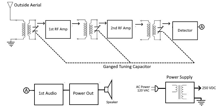
FIGURE 1. Tuned Radio Frequency (TRF) receiver block diagram.
Besides the complications of maintaining frequency alignment while simultaneously tuning multiple stages, TRF radios generally lacked sensitivity and were prone to instability (oscillation and annoying whistles). They also required a bulky and expensive power transformer to supply filament/heater voltage to the tubes. I once repaired a TRF radio with a separate transformer and power supply that weighed over 25 pounds!
With the introduction of the superheterodyne receiver, most of these limitations were overcome. Because of the increased sensitivity, the outside antenna was replaced with a loop antenna tuned by a variable capacitor to the AM broadcast signal. The multiple RF stages were replaced with a mixer/local oscillator stage and a single Intermediate Frequency (IF) stage.
The transformer was eliminated by the introduction of tubes with heaters that could be connected in series directly across the emerging, standardized 120 VAC line voltage. The result was a more compact and space-saving design that along with standardization became the All American Five (AA5) radio.
By 1940, the new octal-based AA5 tubes began to appear in radios. They included the 12AS7 local oscillator/mixer, the 12SK7 IF amplifier, the 12SQ7 detector/first audio amplifier, the 50L6 audio power amplifier, and the 35Z5 rectifier. The first number in the tube type designates the heater voltage. As already suggested, the sum of the heater voltages is close to 120 — just right for a series connection across a 120 VAC power line!
In time, large floor model radios began to disappear from sales floors, replaced by compact tabletop designs using the AA5 circuit. By the late 1940s, a great variety of AA5 models were being mass produced by dozens of radio manufacturers. Internally, they were much the same, so style and outward appearance became the principal selling features.
By 1950, miniature seven-pin versions of the original octal tubes came into use. These were the 12BE6 local oscillator/mixer, the 12BA6 IF amplifier, the 12AV6 detector/first audio amplifier, the 50C5 audio power amplifier, and the 35W4 rectifier. Smaller and sleeker styles were possible, including designs with built-in clocks that could wake you in the morning to your favorite radio station and brew your first cup of coffee via an auxiliary AC outlet.
Over the course of 30 years, millions of AA5 radios were manufactured and sold. Because of the limited lifetimes of tubes and other components, a huge service repair industry flourished. The entry of television in the early 1950s was predicted to spell the doom of radio but that never happened.
Eventually, transistor radios using less power and sporting greater reliability took the market and the AA5 disappeared. The superheterodyne design remained, however, with transistors replacing tubes.
AA5 Operating Theory
The loop antenna and RF tuning capacitor shown in Figure 2 form a tuned circuit that selects the desired AM broadcast station.
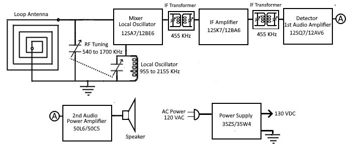
FIGURE 2. Superheterodyne receiver block diagram.
The mixer/local oscillator (12SA7/12BE6) converts the AM broadcast signal to 455 kHz by mixing the AM broadcast and local oscillator signals. Mixing generates two signals identical to the original AM broadcast signal. One is equal to the sum of the mixed signals and the other is equal to the difference. The tuned circuits of the first IF transformer pass only the 455 kHz difference signal (refer to the Sidebar 1).
When mixing two signals to achieve a 455 kHz difference, there are two options: the local oscillator frequency can be below or above the AM broadcast frequency. The “below” option is rejected because multiples of the local oscillator frequency can appear in the AM broadcast band and cause interference. The higher option is chosen because its multiples are above the AM broadcast band. Using a second variable capacitor ganged with the RF tuning capacitor, the local oscillator frequency ranges from 955 to 2155 kHz to tune the AM broadcast band, 540 to 1,700 kHz.
SIDEBAR 1.
The IF amplifier (12SK7/12BA6) amplifies the 455 kHz signal and passes it to a second IF transformer for additional filtering. The two IF transformers and the single IF amplifier provide all the selectivity (adjacent channel rejection) and gain needed for good AM reception. The detector/first audio amplifier (12SQ7/12AV6) performs two functions. First, the diode section of the tube rectifies the amplitude modulation of the 455 kHz broadcast signal detecting it as an audio signal. At this point, a variable resistor (a potentiometer) in the audio path acts as volume control. Second, the triode section of the tube amplifies the audio before passing it to the power amplifier (50L6/50C5) that increases the audio signal’s power to listening level in the speaker.
The power supply of the AA5 consists of a half-wave rectifier (35Z5/35W4) that — along with electrolytic capacitors — converts the 120 VAC to the operating voltage of 130 VDC. Elimination of the power transformer reduced cost and saved space, plus it provided a side benefit. Unlike transformer models, AA5 radios could operate on 120 VDC as well as 120 VAC. At that time, areas of the US operated on a 120 VDC power grid.
AA5 FM Project Design
For the AA5 FM project design, the AM audio source would obviously be the AA5 radio. For the FM audio source, I chose the TEA5767 FM receiver module. I now had two design areas to address.
First, for the audio design, I would simply switch the input side of the volume control between the existing AM detector and the FM audio output of the TEA5767. In this way, the radio’s volume control would handle volume for both the AM and FM audio sources.
Second, for the station selection design, I would sense the local oscillator frequency and use it to select the desired FM station. I would need a circuit to capture and condition the local oscillator signal for processing by a microprocessor. The microprocessor could then control station frequency via the TEA5767 FM module.
Figure 3 shows a block diagram depicting the AA5 FM project design in more detail. In AM mode, the radio operates normally. Station WZZZ 600 kHz tunes at the 600 dial position. Internally, the local oscillator operates at 1,055 kHz — 455 kHz above the received frequency 600 kHz. WZZZ’s signal is converted to 455 kHz, amplified, detected, and its audio delivered to the speaker.
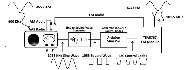
FIGURE 3. AA5 FM project block diagram.
In FM mode with the dial set at 600, the 1055 kHz local oscillator signal is captured by the sine-to-square wave converter and changed to a square wave of the same frequency. The microprocessor — an Arduino Pro Mini — determines the square wave’s frequency and (from a lookup table) associates it with FM station KZZZ at 101.5 MHz. Utilizing an I2C serial interface, the Pro Mini sends the FM station’s frequency to the TEA57567 FM module.
Lastly, the audio output of the TEA5767 is routed through the volume control and eventually to the speaker. The only wired modification to the AM radio is a switch to select the audio source.
Circuit Description
Shown in Figure 4 is the sine-to-square wave converter circuit. For an antenna to pick up the local oscillator signal (waveform A), I wound a few turns of insulated No. 22 solid wire around the local oscillator/mixer tube. So as not to load down the weak local oscillator signal, I wanted a high impedance input for the first amplifier stage. My choice was a MPF102 JFET transistor shown as Q1.
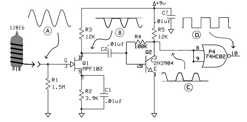
FIGURE 4. Sine-to-square wave converter schematic.
Under normal biasing, Q1’s gate-source junction is reverse-biased, so the load to ground is simply R1 — a 1.5 megohms resistor. Q1 provides a voltage gain of 10 and, because of the gate bias chosen, clips one half of the input sine wave (waveform B).
For the second stage Q2, I chose the NPN transistor 2N3904. Q2 provides an additional gain of 20 and is biased to clip the top of the input half-sine wave (waveform C). I finished with a 75HCT02 two-input NOR gate configured as an inverter. Its purpose is to square up the signal (waveform D) and interface to the Arduino with correct logic voltage levels (0 and 5 VDC).
I chose the Arduino Pro Mini because it was developed for applications with limited space. It comes in 3.3 VDC and 5 VDC versions — both utilizing a 16 MHz AVR ATmega328 microprocessor. I chose the 5 VDC version. The Pro Mini is fully Arduino software compatible and features an FTID interface for programming. Figure 5 shows two available Pro Mini versions.
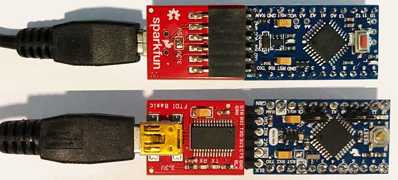
FIGURE 5. Top: SparkFun versions of the Arduino Pro Mini and FTID breakout board. Bottom: generic version.
The top Pro Mini is from SparkFun and is shown with the companion SparkFun FTID basic breakout board that connects to a PC for programming the Pro Mini. The bottom shows one of the many generic version Pro Minis. The one shown is from HiLetgo that I purchased on Amazon. Both worked equally well for the AA5 FM project.
Note that the FTID board plugs in upside down on the generic version. Check and match the labeled pins on any generic Pro Mini to determine the correct orientation for the SparkFun FTID board.
The TEA5767 FM radio module shown in Figure 6 is designed around the Phillips TEA5767 FM receiver chip.
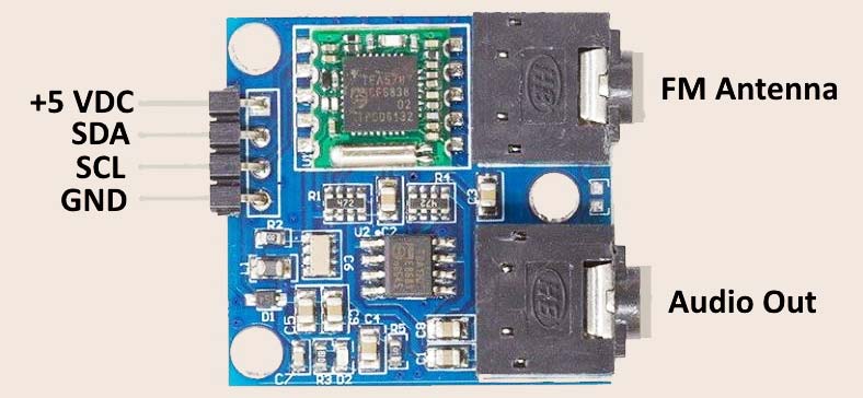
FIGURE 6. TEA5767 FM receiver module.
The single-chip TEA5767/68 is a miniature, digitally tuned FM receiver that replaces passive components and analog devices with digital circuitry. I used the Pro Mini to control the TEA5767 by sending operational commands over an I2C two-wire serial interface. The SDA pin is the I2C data line and SCL pin is the I2C clock.
Figure 7 shows the interconnection of the Pro Mini and TEA5767 FM module. The local oscillator square wave connects to pin 5 of the Pro Mini. Arduino pin 5 is a multi-use pin that I configured as an input to a 16-bit counter. By counting the number of square wave cycles in 10 milliseconds, I could determine the local oscillator frequency to the nearest 10 kHz. Knowing AA5’s local oscillator frequency, I could then select an FM station frequency from a table and send it via the I2C two-wire serial interface to the TEA5767. The TEA5767 digitally tunes to the frequency and the FM station’s audio appears at the FM audio phone jack.
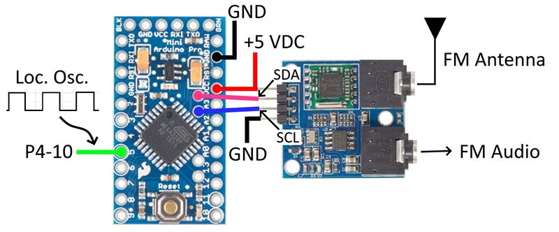
FIGURE 7. Interconnection diagram of the Arduino Pro Mini and TEA5767 FM module.
The complete schematic including the power supply is shown in Figure 8. The AA5 FM adapter operates from a 9 VDC wall adapter (not shown) plugged into the DC jack. A power on/off switch (shown in the off position) doubles to isolate the Pro Mini from the power circuitry when connected to a PC for programming. The sine-to-square wave circuitry operates from the 9 VDC. An LM78L05 regulator IC supplies the 5 VDC for the Pro Mini and TEA5767 FM module.
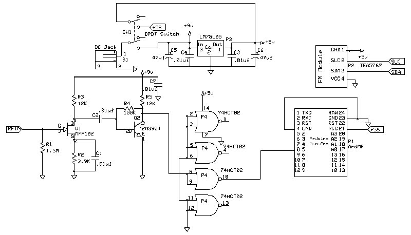
FIGURE 8. Full schematic of the AA5 radio FM adapter.
Construction
I constructed the AA5 FM adapter prototype shown in Figure 9 on a 2.5” x 3.8” prototyping board.
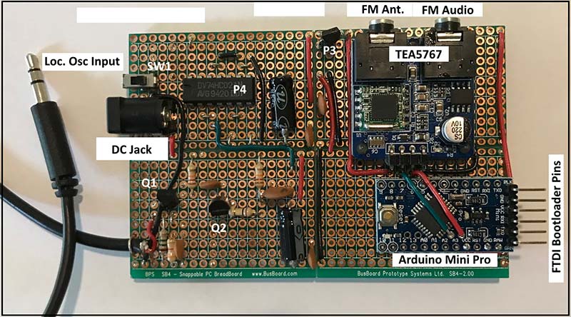
FIGURE 9. First prototype of the AA5 radio FM adapter.
Following a few minor circuit revisions, I designed a printed circuit board (PCB) and ordered it from ExpressPCB. As often happens, the PCB circuitry was fine but some of the through holes were slightly off, requiring a second PCB order. The front (left) and back (right) Version 2 PCB is shown in Figure 10.
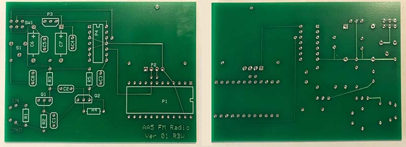
FIGURE 10. Printed circuit board for the AA5 radio FM adapter. Left: Front of PCB. Right: Back of PCB.
Figure 11 shows the PCB fully populated. I used 14-pin and 24-pin (0.6“ wide version) DIP sockets for the 74HCT02 and Pro Mini, respectively. The reason? It’s a real pain to unsolder and replace these devices if they fail.
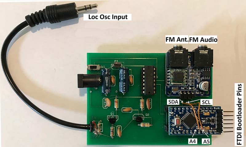
FIGURE 11. Completed PCB version of AA5 radio FM adapter.
Note the two short wires that interconnect SDA and SCL (the I2C pins) on the Pro Mini and TEA5767. As shown, Pro Mini pins A4 and A5 are not part of the 24-pin DIP socket, so connect from within the Pro Mini board to matching holes below the TEA5767.
The procedure for mounting the TEA5767 was a bit complicated. The four pins connecting the TEA5767 to the AA5 FM PCB pointed straight out instead of downward. My first step was to bend them at 90 degrees so that they would pass through the pads in the AA5 FM PCB.
The next problem was securing the TEA5767 to the AA5 FM PCB. I didn’t have screws and spacers small enough to match the holes in the TEA5767 PCB. As an alternative, I used three single breakaway pins. I soldered the longer end of each in the pads corresponding to the mounting holes in the TEA5767 PCB. I then set the TEA5767 module in place passing the shorter ends through the holes in the TEA5767 PCB. After bending the shorter ends over the top of the PCB, I applied a small amount of epoxy glue in each hole.
Finally, while holding the TEA5767 module firmly in place, I soldered the four connector pins between the TEA5767 and the AA5 FM PCB and allowed the epoxy to harden. Figure 12 illustrates this procedure for one mounting hole.

FIGURE 12. TEA5767 FM module mounting detail.
Lastly, a short length of stereo 3.5 mm audio cable serves as the input to the sine-to-square wave converter circuit. I connected one of the internal conductors to the gate of Q1 at the pad provided. I connected the shield to the ground pad. I used the second set of pads near the edge of the board to create a strain relief for the cable. I placed a short length of “U” shaped wire over the shielded cable, passed it through the pad holes, and twisted the ends on the back side of the PCB. A dab of solder on the twist fixed it in place.
Modifying the AA5
First things first.

Warning! Never examine or modify an AA5 radio if it’s plugged into a power outlet! Deadly voltages are present!
While the modifications necessary for the AA5 FM project are minor, they should not be attempted without the proper tools and attention to safety at every step. If you’re not comfortable making the modifications, seek out someone who has the experience and tools to do the work safely! (Refer to Sidebar 2.)
Replacing the line cord with a polarized one is a good idea, but it must be done so that the wide blade (powerline ground) is connected directly to the chassis and the narrow blade (powerline “hot”) is connected to the on-off switch. Not all AA5s come wired this way, so complete rewiring of the AC input circuitry becomes necessary. If you don’t have the skill and experience to tackle such a task, find a competent electronic technician to make the modification for you. For a complete description, refer to the modification procedure at
https://www.antiqueradio.org/safety.htm.
SIDEBAR 2.
As noted previously, my goal was to add FM capability without changing the AM radio’s basic operation. As shown in Figure 13, I added a switch on the back of the radio to select audio from the radio’s AM detector or a miniature 3.5 mm phone jack on the back of the radio.
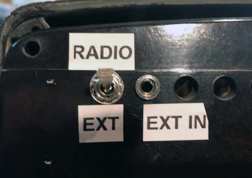
FIGURE 13. External input and selection switch on AA5 radio’s back.
Taking this approach, external audio could originate from a variety of sources (MP3 player, smartphone, etc.). Or, for my project, from the TEA5767 FM module.
On the left in Figure 14 is a typical 12SQ7/12AV6 circuit before modification. Beside it is the circuit, modified for external audio. I broke the connection between the AM detector circuit and the volume control at point “X.” I then brought both connections out to a double pole/double throw toggle switch on the back of the radio. The switch selects either the AA5 detector circuit or the miniature phone jack.
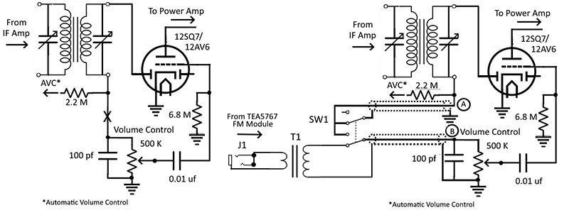
FIGURE 14. AA5 radio detector/audio amplifier modification.
The selected signal connects back to the volume control. From there, it’s amplified and played through the speaker.
From previous experience, I found that in EXT mode, some radio audio would “bleed” through — especially when tuned to strong local AM stations. To remedy this, I used the second pole of the switch to short the AM detector signal source to ground when the external jack input is selected. To further avoid the bleed problem, don’t choose local AM station frequencies for FM mode!
Shielded cable should be used to and from the selector switch. Sacrificing a miniature male-to-male stereo cable is a good way to obtain the short length needed. The stereo cable has two inner conductors surrounded by the ground shield. Using it means only one shielded cable is needed to make the two connections.
As there was no convenient hole in my AA5 chassis to pass the cable through, I drilled a hole being careful not to drill into and damage a component.
To couple external audio, I used a small audio transformer that would isolate the EXT source from the AA5 radio’s circuitry — particularly the chassis ground. In the old days, plugs were not polarized. Thus, there is a significant chance that the chassis is connected to the powerline’s “hot” side, making the radio chassis a potential death trap! The possibility of a hot chassis explains the use of an isolating transformer and — more importantly — underlies the reason for never exposing yourself to possible danger by examining or modifying a tube radio when it’s plugged into an AC power outlet!
Referring to Figure 15, make sure that A and B inner conductors connect to existing circuits at fixed terminals. It may be necessary to add a small terminal strip at point A to meet this requirement.
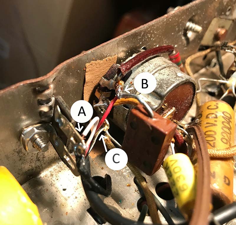
FIGURE 15. AA5 radio modification, internal circuit detail.
For ground, use the lower end of the volume control (point C), not the chassis ground.
Figure 16 shows the source selection switch, miniature phone jack, and transformer mounted on the radio’s back. The transformer had only small metal “ears” for mounting. To mount the transformer, I drilled two small holes in the back of the radio, inserted the ears, and epoxied them in place.
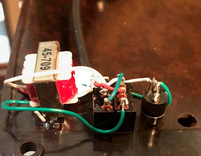
FIGURE 16. AA5 radio modification, external circuit detail.
As shown in Figure 17, I avoided a permanent connection between the FM adapter and the radio by wiring the local oscillator “antenna” to a miniature phone jack mounted on the back of the radio.
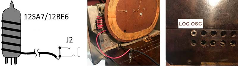
FIGURE 17. AA5 radio local oscillator antenna detail.
Note that the antenna wire connects to both internal conductor pins and the ground is not connected. The finished back of the radio is shown in Figure 18.
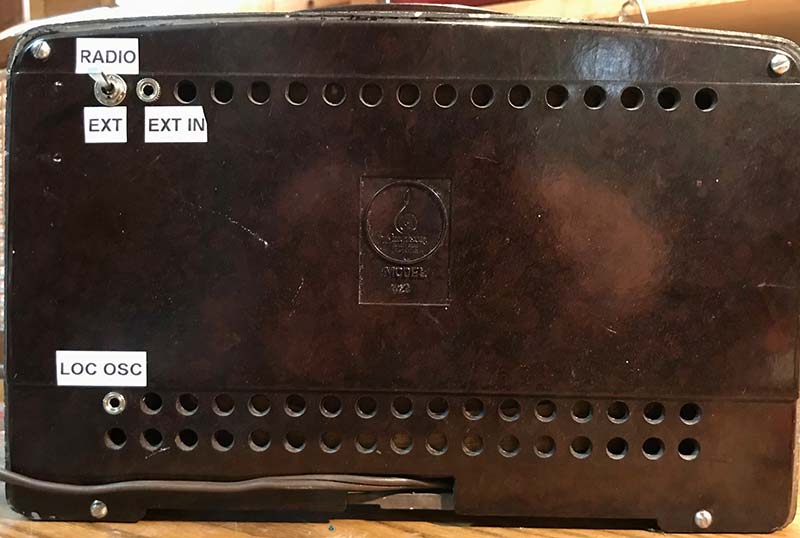
FIGURE 18. View of AA5 radio with modifications.
Software
One of the great advantages of using an Arduino is the enormous availability of library code available to assist in coding projects. For the AA5 FM project, coding was greatly simplified using three libraries:
- FreqCounter Library. This library provided a simple way to determine the frequency of the incoming “leakage” signal using one of the Arduino’s internal counters.
- TEA5767Radio Library. With this excellent library, operating the TEA5767 FM module was easy to do. Just send the station’s frequency and you’re done!
- Wire Library. This library code implements I2C serial communication with the TEA5767 FM module.
These libraries are available in the article downloads. This is the outline of the code that ties these libraries together.
1. Two tables in the code create the mapping between the leakage signal frequency and the frequency of the FM station assigned to it. Here’s an example.
Table I: int AMFreq[] = {600,720,1000};
Table II: float FMFreq[] = {89.1,94.5,104.9};
The example code creates the following mapping: 600 kHz maps to 89.1 MHz; 720 kHz to 94.5 MHz; and 1000 kHz to 104.9 MHz. For example, if the AM dial is tuned to 720 kHz, the TEA5767 FM module will tune to 94.5 MHz. More or fewer table entries are permitted so long as the number of items is the same in both tables.
Note: This is the only code that needs changing to adapt the AA5 FM project to your FM station selection.
2. On start-up, the code enters the SCAN WHILE loop indicated by the extinguished Arduino LED. In the SCAN WHILE loop, I read the leakage frequency and, if the frequency is within 20 kHz of an AMFreq table frequency, switch to the TUNE WHILE loop, turn on the Arduino LED, and send the mapped FM frequency in the FMFreq table to the TEA5767 FM module.
3. In the TUNE WHILE loop, I apply the same 20 kHz criteria and switch back to SCAN WHILE loop if the leakage signal frequency differs from the current AMFreq table frequency. So long as the leakage signal frequency stays within 20 kHz of an AM table frequency, the TEA5767 stays tuned to the selected FM station. The 20 kHz allowance makes tuning easier and helps eliminate loss of tuning with drift in the local oscillator frequency.
I used the standard Arduino IDE (integrated development environment) to edit, compile, and download the AA5 FM program. The program code is available in the downloads.
Putting It All Together
The final step was mounting the AA5 FM adapter PCB to the back of the radio. I considered screws and stand-offs but decided to use self-sticking Velcro™ picture hanging strips. I cut one of the strips in half length wise.
Following the instructions on the package, I attached two strips to the long-side edges of the AA5 FM adapter PCB and the back of the radio.
Figure 19 shows the final configuration AA5 FM adapter with all cables and the FM whip antenna in place. When switch SW1 is in the up position, the AA5 FM adapter is turned off and the FTID interface pins are isolated from the onboard 5 VDC supply. Use this switch position to program the Pro Mini. In the down position, SW1 turns on the AA5 FM adapter.
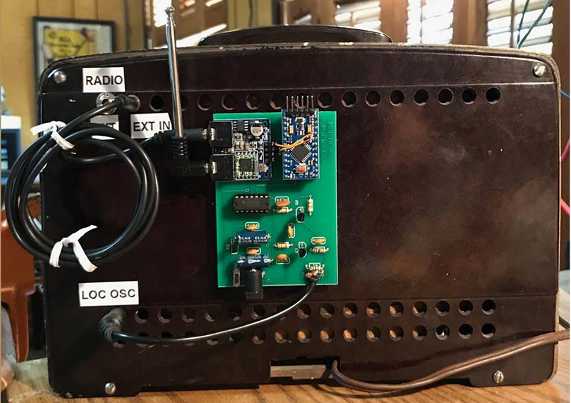
FIGURE 19. View of AA5 radio with FM adapter.
With completion of the AA5 FM project, I successfully married mid-20th century technology with 21st century digital electronics to give new life to my All American Five radio.
I only wish Peter Wright were here to see his 20th century idea used in the 21st century! NV
Parts List
| AA5 Interface Board |
| Item |
Description |
Ordering Information |
| C1 |
.01 µF 50 VDC Capacitor |
Jameco 15229 |
| C2 |
.01 µF 50 VDC Capacitor |
Jameco 15229 |
| C3 |
.01 µF 50 VDC Capacitor |
Jameco 15229 |
| C4 |
.01 µF 50 VDC Capacitor |
Jameco 15229 |
| C5 |
47 µF 50 VDC Capacitor |
Jameco 135319 |
| C6 |
47 µF 50 VDC Capacitor |
Jameco 135319 |
| C7 |
.01 µF 50 VDC Capacitor |
Jameco 15229 |
| P1 |
Arduino Pro Mini – Five volt |
Sparkfun or Amazon HiLetgo |
| P2 |
TEA5767 FM Receiver Module |
eBay TEA57567 |
| P3 |
LM78L05 % VDC Regulator |
Jameco 51182 |
| P4 |
74HCT02 CMOS NOR Gate |
Mouser 595-SN74LS02NE4 |
| Q1 |
MPF102 JFET |
Jameco 26403 |
| Q2 |
2N3904 NPN Transistor |
Jameco 38359 |
| R1 |
1.5M 1/4W Resistor |
Jameco 691622 |
| R2 |
3.9K 1/4W Resistor |
Jameco 691008 |
| R3 |
12K 1/4W Resistor |
Jameco 691121 |
| R4 |
100K 1/4W Resistor |
Jameco 691340 |
| R5 |
12K 1/4W Resistor |
Jameco 691121 |
| S1 |
Power Input Jack |
Jameco 2210677 |
| SW1 |
DPDT Switch |
Jameco 161817 |
| |
24-pin DIP Socket (0.6” wide) |
Jameco 112264 |
| |
14-pin DIP Socket |
Jameco 112214 |
| AA5 Radio Modification |
| Item |
Description |
Ordering Information |
| |
3 ft Male-to-Male Audio Cable |
Parts Express 240-052* |
| T1 |
Audio Transformer |
Jameco 2210992** |
| SW1 |
DPDT Toggle Switch |
Jameco 317472 |
| J1 |
3.5 mm Panel Jack |
Parts Express 090-317 |
* I sacrificed this cable to make the volume control switch SW1 and local oscillator antenna shielded cables.
** The audio transformer I used in this project is no longer available. This 600-to-600 ohm transformer works equally well, although the mounting will be different.
Resources
Express PCB
https://www.expresspcb.com
Jameco Electronics
https://www.jameco.com
Parts Express
https://www.parts-express.com
SparkFun Electronics
https://sparkfun.com
Arduino Microprocessor
https://www.arduino.cc
I2C Serial Protocol
https://www.thegeekpub.com/18351/how-i2c-works-i2c-explained-simply/
MI5 - Military Intelligence Section 5 - United Kingdom’s Domestic Counter-Intelligence and Security Agency
https://en.wikipedia.org/wiki/MI5
Superhet Receiver
https://en.wikipedia.org/wiki/Superheterodyne_receive
TRF Receiver
https://en.wikipedia.org/wiki/Tuned_radio_frequency_receiver
Guglielmo Giovanni - Early Radio Pioneer
https://en.wikipedia.org/wiki/Guglielmo_Marconi
Peter Wright - British MI5 Intelligence Officer and Author of “Spy Catcher – The Candid Autobiography of a Senior Intelligence Officer,” Viking Penguin, Inc., N.Y.
Downloads
What’s in the zip?
Code
PCB File
Schematic
Libraries