C Programming • Hardware • Projects
Recap
Last time, we finished discussing the preliminaries for the avrtoolbox open source project and said that if all goes well, we would continue with avrtoolbox by writing an elementary serial function library. And we will, but just not quite yet. I got off on another tangent, this time based on my releasing a revision to my book Virtual Serial Port Cookbook. This is the first of a two-part series providing a very convenient way to hook up a serial connection between a PC and a solderless breadboard for use in electronics prototyping.
FIGURE 1. Virtual Serial Port Cookbook.
My book is about the FTDI FT232R USB to UART converter that lets folks use their PC USB connection to emulate the much easier to use serial communication port that served our prototyping needs so well for so long. The book revision is mainly to incorporate two additional FT232R prototyping boards: the Gravitech board (http://store.gravitech.us/ftusbtouabrb.html — note this is .us NOT .com) and the Bob-00718 from SparkFun (www.sparkfun.com/products/718).
You may already know that the Arduino, up until the most recent release, used this very chip (FT232RL) for serial communications which is a testament to its ease of use. To tie this to Atmel AVRs — which is what this Workshop is supposed to be about — we’ll revisit the BreadboArduino — an Arduino on a breadboard we discussed in Workshop 21 — only this time with the Gravitech board AND a kit available from Nuts & Volts, so that you can get all the parts in one place without having to look all over the place.
This is NOT a Shootout!
There are many really good breakout boards for the FTDI FT232R IC. I’ve got a bunch from various companies and I have yet to find one that didn’t work as advertised. So, our goal here is not to say that any one board is better than another. As mentioned, I’ve chosen one from Gravitech and the other from SparkFun — both fine boards from fine companies. The project kit that goes with these articles has the Gravitech board, but the SparkFun board would do just as well (and you can follow the instructions in Workshop 21 if you want to use that board).
Both of these boards have two LEDs attached to show USB transmission and reception traffic, and while it can be a convenient debugging feature it has the downside of blocking two of the CBUS pins that could otherwise be used for general input/output or some other special features you’ll learn about later. If you want to use these features, you’ll have to make changes to the PCB of the ‘voids warranties’ and ‘runs with scissors’ variety that I won’t provide instructions for (I get yelled at entirely too much as it is). I’ll admit I do this sort of thing all the time myself (though I don’t yell at the folks who sold me the board I trashed). Each of these boards provides the following:
- A Virtual COM port (imitates legacy PC serial ports).
- FTDI FT232R USB UART IC single chip USB solution.
- UART voltage levels of either 5V or 3.3V (not RS-232 voltages*).
- Easy to use, royalty-free FTDI drivers for Windows, Linux, and Mac.
- PC Virtual COM port drivers for legacy serial communications with microcontroller UARTs.
- Bit-bang mode using special drivers and software.
- Fourteen I/O lines for use with RS-232, bit-bang, or special function modes.
- USB bus power of 5V at up to 500 mA or regulated 3.3V at up to 50 mA.
- Unique serial number for security-dongle applications using FTDIChip-ID™.
- Clock generator to drive microcontrollers (6, 12, 24, and 48 MHz).
- LED drivers to show serial traffic.
*Please note that these boards do not output RS-232 voltage levels; instead they output TTL UART voltage levels of either 5V or 3.3V which is a good thing if you are connecting directly to a microcontroller UART. One of the big problems with store-bought USB to serial port converters is that in order to use them with a microcontroller, you have to convert from the RS-232 voltage levels to the UART voltage level. However, these boards allow you to bypass that step. The book has a chapter that tells you how to use a special RS-232 voltage converter IC to turn these boards into a fully functional USB to RS-232 conversion cable.
These boards also allow you to use your PC to communicate with and power a breadboard electronic prototyping project. You have two choices for communicating: either use the VCP (Virtual COM port) drivers for serial ports, or use the FTDI D2XX direct drivers from a special Dynamic Link Library (DLL) to directly control access to the USB device and pin I/O. You can also provide your project with either 5V up to 500 mA (though I recommend that you don’t exceed 100 mA just in case your USB is from an un-powered hub that limits the current) or 3.3V up to 50 mA from the PC USB cable. Or, you can choose to power the board and your project from your own power supply.
These boards can be used in any breadboard project requiring a drop-in serial communications module, since they have standard .1” pin spacing and use gold-plated square header pins that are longer and much more sturdy than usual IC pins or ordinary ‘Stamp’ type board pins. (The SparkFun board does not come with the header pins, so if you get their board, you’ll need to purchase the legs separately.)
Gravitech
As of this printing, Gravitech has the best price for one of these boards that I know about which is $12.99 for item #FT232RL-BO (Figure 2).
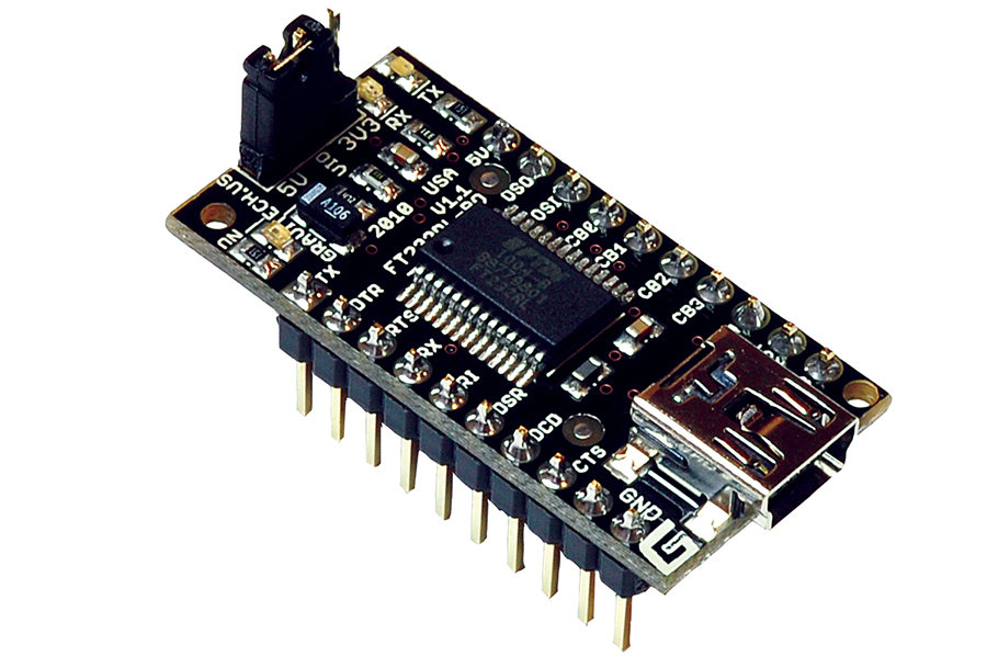
FIGURE 2. Gravitech board FT232RL-BO.
Sparkfun
The BOB-00718 (Figure 3) from SparkFun was $14.95 in February ‘10. Remember to purchase the legs separately.
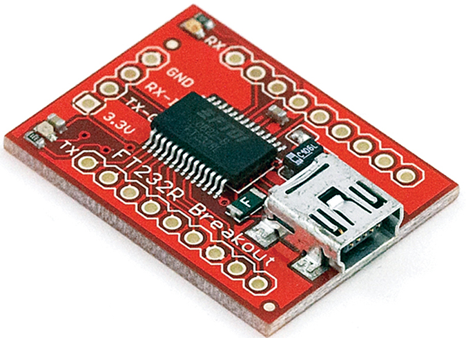
FIGURE 3. SparkFun board BOB-00718.
Why the Heck Imitate a PC Serial Port with USB?
In the olden days, the PC serial port had a Windows software serial port driver and hardware link based on the RS-232 electrical specification, and used a DB-9 connector and a UART (Universal Asynchronous Receiver Transmitter).
It wasn’t exactly simple for a novice PC user to hook up a serial link since it required the user to select software interrupts and set hardware jumpers — something you and I as certifiable geeks like to do, but something that normal people hate and tend to screw up. These and other complications led to the development of the Plug and Play initiative (more commonly and correctly known as Plug and Pray). One part of all this was to replace the serial port with USB to help simplify things which it did for the casual user, but made the developer’s life (yours and mine) much more complicated. USB also obsoletes lots of perfectly good serial devices and a couple of decades of knowledge of how to do robust RS-232 style serial communications between PCs and external serial devices.
I’ve read the USB specification, and I’m here to testify (brother, amen) that the old COMPORT/UART/RS-232 was a piece of cake compared to USB. I worked with USB when it first came out and my brain is worse for the wear. Fortunately, some geniuses thought that they would simplify the life of not just the user but the developer too by creating a transitional concept, that is, to have an old fashioned RS-232 style serial port that runs over USB. The FTDI folks call this a Virtual Communications Port (VCP). It allows legacy applications to continue to use the old microcontroller code and the Windows serial port software with the USB part, all tidily bound up in a black box that the developer doesn’t have to open. These transitional devices give us the best of both worlds: the ease of using the serial port and the ubiquity of using USB. The developer has the option of adding RS-232 level converts to completely emulate the old way of doing things, or leaving the level converters off and outputting voltage levels directly compatible with a microcontroller’s UART.
The FTDI solution to this problem is to dedicate a microcontroller to accept USB data and translate it into UART type data. They also have learned along the way that this ‘dedicated’ microcontroller can also have some features that aren’t really part of either USB or UART. For example, the FT232R has pins that can be used to twiddle transmission indicator LEDs, bit-bang I/O (Input/Output), contain a unique serial number (security dongle anyone?), or even provide a clock and power for another microcontroller. All this adds not only to easing the job of communication between the PC and an external serial device, it also adds complexity that can at times be quite, well, complex. We’ll address some of the complexity in next month’s Workshop column.
FT232R Quick Start Guide
This section will help you to get started with the breakout board you’ve chosen to use for the Virtual Serial Port Cookbook (2011 revision) projects. We will begin with the Gravitech board and follow with the SparkFun board. Each of these boards installs the same way on the PC and each uses USB software the same, so the last section will cover installation and use with a terminal program as a generic discussion.
How the Boards Differ
Each of these boards differs in some respects from the others. They will all function perfectly well for our hardware and software demonstrations. However, since the pin-outs are different, the wiring on the breadboard hardware experiments will be different.
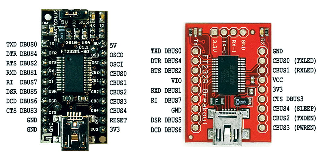
FIGURE 4. Board pin-outs.
Pin-outs:
Each board has a different pin-out that will be shown shortly. The hardware demonstrations use a generic FT232R component that does not show either the actual PCB pin-outs or the power pins for any of the boards. The user will be expected to learn in this section how the schematic symbol actually maps to the real board and then in later sections apply that knowledge to the experiments shown.
Size:
Each of the boards differs slightly in size.
Connectors:
Both boards use the small MiniB connectors, so you will need the appropriate USB cable.
Power:
The Gravitech board can be configured for either five or 3.3 volts; the SparkFun board only works at 3.3 volts (refer to their website to convert it to five volts). The pin location for voltage and ground varies between each device and is not shown in the hardware demonstration schematic. Users should read the section on setting up their device and then preset the power before doing the hardware demonstrations.
LEDs:
Both the SparkFun and the Gravitech boards have LEDs to indicate TX and RX. The TX and RX indicators are taken off two of the CBUS pins and must be considered in circuits that use these pins for other applications.
OSC:
The Gravitech board has two OSC pins that we will not consider in this article.
Generic Schematic Symbol Versus the Actual Boards
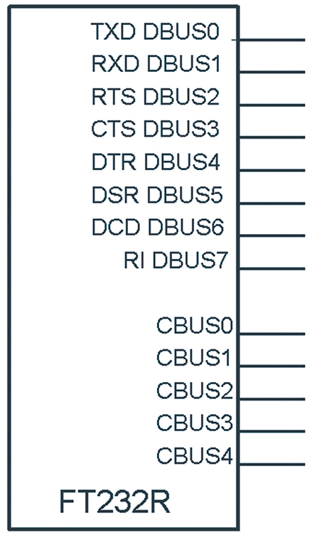
FIGURE 5. FT232R schematic symbol.
Each of our three boards is wired up differently, so we will use a single generic schematic symbol for our hardware demonstrations that will show only the common pins used by each board. In the following sections, you will see how to set up your particular board and you will test your setup with a simple loop-back test (you send a character and the FT232R sends it back to you). For subsequent demonstrations, you may need to refer back to this section to understand the actual breadboard layouts.
Power
The USB bus can provide up to 500 mA power to a USB device, but certain rules must be followed. Violating the rules can result in your PC assuming a USB bus power fault, and the PC may then shut down (no warning, just a black screen and bye-bye to all your unsaved work — this is not an official ‘fact’ but a personal observation). Save your work frequently when playing with these devices and be prepared to reboot your system.
The USB peripheral tells the USB host how much power it needs in 100 mA units up to 500 mA. It cannot use more than 100 mA while starting up before making a request for more power. The USB host can deny the peripheral’s request for more power. Also, if the USB host tells the peripheral to go into suspend mode, it must not use more than 500 µA. This can get complex.
For instance, a device off a bus-powered hub cannot use more than 100 mA, but you can have hubs with external power that can supply the full 500 mA. For the quick start guide, we will assume that the device is powered either directly from a PC or from an externally powered hub so that we can use up to 500 mA. Don’t forget if you use the 3.3V from the FT232R, you are limited to 50 mA.
Setting Up the Gravitech Board
Layout and Schematic:
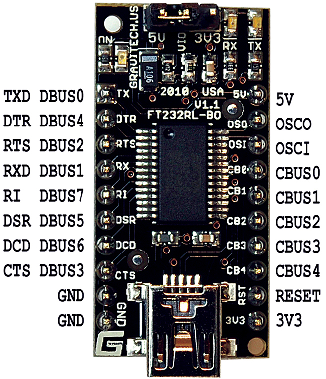
FIGURE 6. Labeled Gravitech board pins.
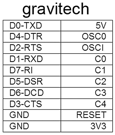
FIGURE 7. Gravitech board hat.
You can find a printable version of the Gravitech board hat shown in Figure 7 in the downloads section for this article.

FIGURE 8. Gravitech board schematic.
Power Wiring:
Select either five or 3.3 volts from the jumper and take the board power from the selected pin.
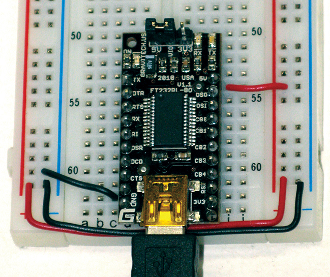
FIGURE 9. Gravitech board wired for USB bus 3.3V.
Setting Up the SparkFun Board
Layout and Schematic:
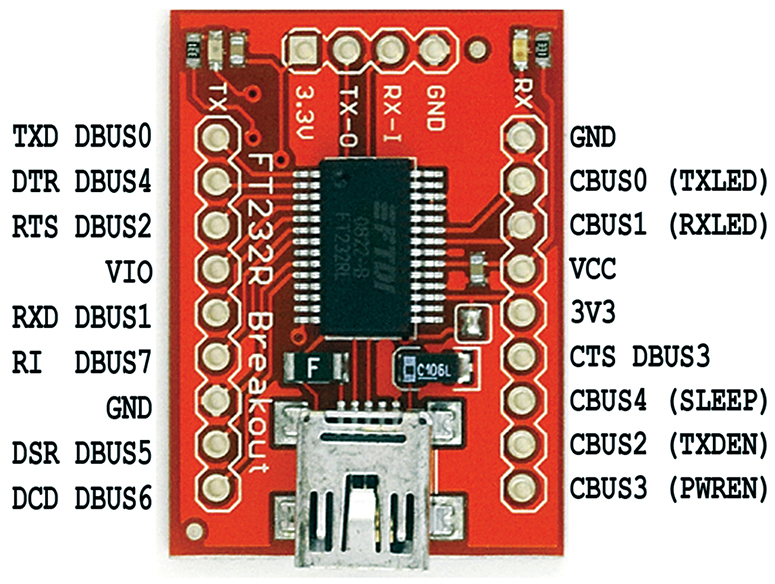
FIGURE 10. Labeled SparkFun board pins.
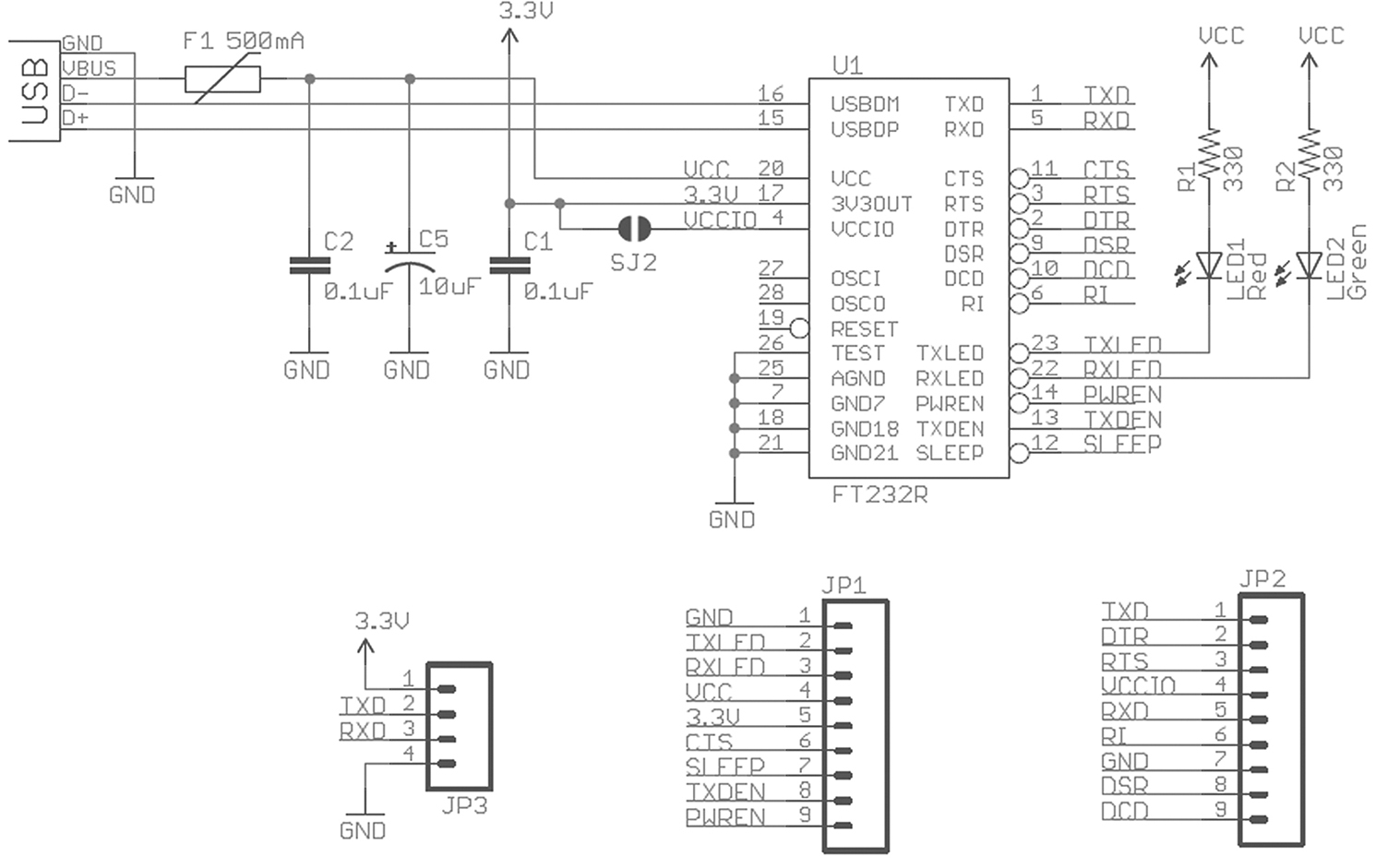
FIGURE 11. SparkFun board schematic.
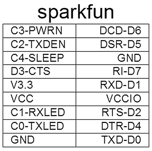
FIGURE 12. SparkFun board hat.
You can find a printable version of the SparkFun board hat shown in Figure 12 at the same websites mentioned previously.
Power Wiring:
The SparkFun board is wired for 3.3 volts but can be converted to five volts – visit their website to see how to do this.
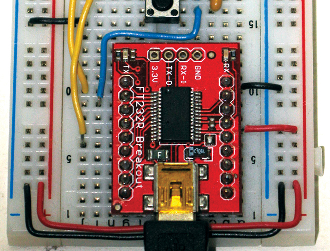
FIGURE 13. SparkFun board wired for USB bus 5V.
Loop-back Test
The loop-back test couldn’t be simpler. Just run a wire from the transmission pin TxD to the reception pin RxD, and whatever you send out on the port will be sent back to you. This is an excellent test to make sure everything is working properly. You may well remember this test later when you get a bunch of stuff on a breadboard and something isn’t working right. This test will eliminate the terminal program, the wire between the PC and the FT232R board, and the board itself as culprits.
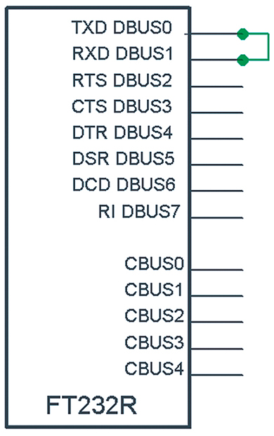
FIGURE 14. Loop-back schematic.
Gravitech loop-back test:
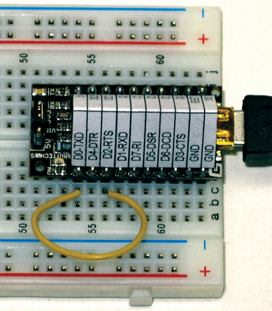
FIGURE 15. Gravitech wearing the pin-out hat for the loop-back test.
Sparkfun loop-back test:
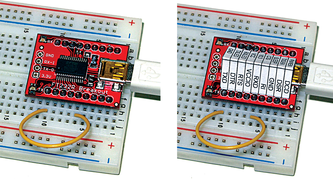
FIGURE 16. SparkFun board loop-back test with and without hat on.
Installation and Use With a Terminal Program
- Plug a USB cable into your PC and the BBUSB.
- If you are using XP, the window in Figure 17 will appear.
- Windows wants to waste a bunch of your time searching for something it won’t find and asks for permission. Click the ‘No, not this time’ radio button. Actually, I’d prefer a less polite ‘Heck NO! Not now, not never!!!’ option, but it isn’t available. Click the ‘Next’ button and the window in Figure 18 will appear.
- Select the ‘Install from a list or specific location (Advanced) radio button, then click the ‘Next’ button and the window in Figure 19 will appear.
- Click the ‘Browse’ button and locate the CDM 2.00.00 directory which contains the FTDI drivers. You can find the FTDI software used in this book in the Nuts & Volts downloads section, or the newest version at www.ftdichip.com. Click the ‘Next’ button and the window in Figure 20 will appear.
- Click Finish and the balloon in Figure 21 will pop up.
- Don’t be shocked to see that the very first Windows Form in the above sequence pops up again. Rather than waste the space showing all the above forms again, just note that two sets of drivers are installed and this second round will proceed exactly as above.
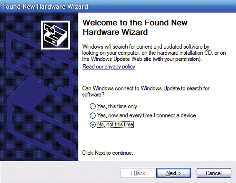
FIGURE 17. Found New Hardware Wizard 1.
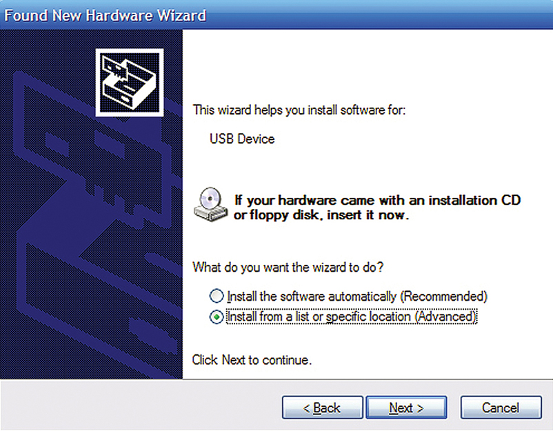
FIGURE 18. Found New Hardware Wizard 2.
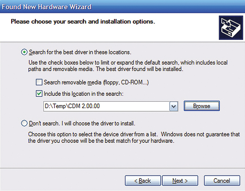
FIGURE 19. Found New Hardware Wizard 3.
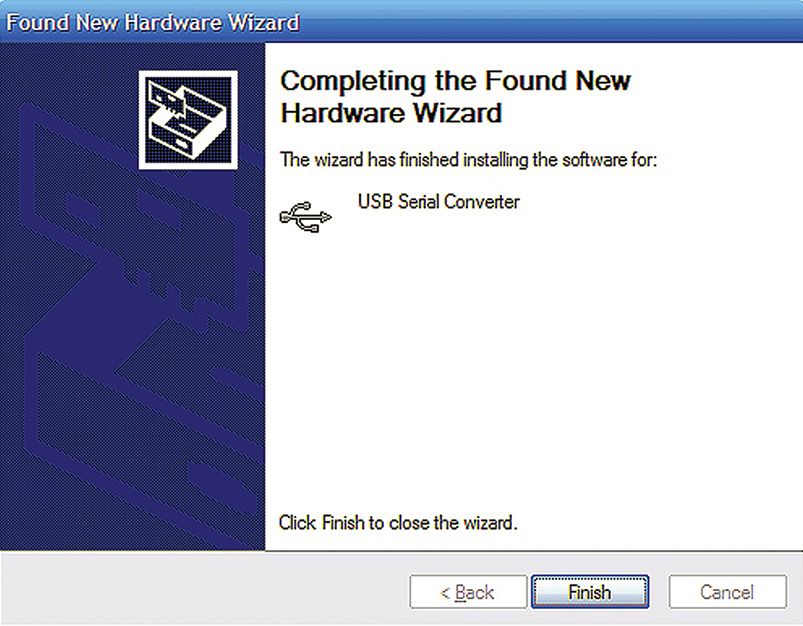
FIGURE 20. Found New Hardware Wizard 4.

FIGURE 21. Found New Hardware Wizard 5.
The Simple Terminal Software
Back in the January and February ‘10 issues of Nuts & Volts, we had workshops on writing a Simple Terminal program using C# .NET. To install this terminal, follow these steps:
- You do have .NET Framework installed, don’t you? You will find out as soon as you try to open Simple Terminal (located in the downloads section) in the next step. If Simple Terminal opens, then you have .NET; if it doesn’t, then get it on the Microsoft website.
- Open Simple Terminal by clicking on SimpleTerm.exe.
- Make sure your FT232R board is plugged into your PC and set up for the loop-back test discussed previously.
- Open the Settings menu item and select the COM port for your FT232R
- Type in ‘Hello World!” and you should receive ‘Hello World!’ as shown in Figure 22.
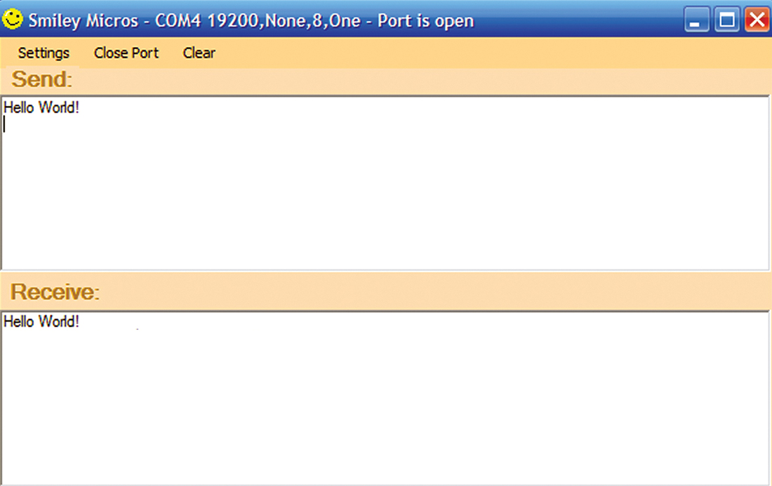
FIGURE 22. Simple Terminal Hello World!
That’s all for the first part of this two-part series. Next time, we look at using the FT232R modem lines, then using it for general-purpose input/output to read switches and light LEDs. Then, we will use a seven-segment LED to make the “World’s Smallest Moving Message Sign.” Finally, we will revisit the BreadboArduino. NV
Vitual Serial Port Cookbook Revision and kit to go with these series of articles can be purchased online from the Nuts & Volts Webstore or call our order desk at 800-783-4624.