When my wife and I moved into our current home a few years back, it didn’t have a doorbell. We live on a quiet cul-de-sac, so it really wasn’t a problem as we had few callers. After a while, I installed a wireless doorbell that lasted about three years. Recently, after writing the series of articles on “A Digital Analog — When a PIC Can Replace a 555,” I decided to make one using a PIC.
The unit I implemented can be operated in either of two modes:
- Select from among eight different tone sequences from a single doorbell switch.
- Up to four doorbell switches, each with its own tone sequence, for different doors/locations.
A combination of the two can be implemented if you want to modify the code provided in the article downloads.
Circuit
The circuit for the doorbell can be seen in Figure 1, and is relatively simple.
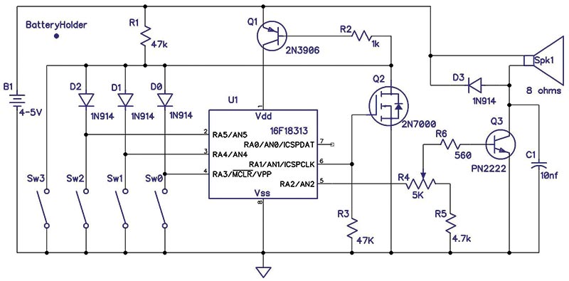
FIGURE 1.
If diodes D0, D1, and D2 ARE installed, then up to four switches can be used to indicate up to four different locations — each having its own tone sequence. Closing any one of the four switches will apply power to the processor. Once the PIC is turned on, the software turns on Q2 which keeps the power on even if the switch is released. If the diodes are NOT installed, the operation is such that switches 0 through 2 are now jumpers. They are decoded to determine which of eight tone sequences is played when Sw3 is closed. Only closing Sw3 will turn on Q1.
The three inputs of the PIC have their weak pullups enabled; the software will invert the state of switches 0 through 2 after reading them. So, in this case, grounding a switch creates a logical one.
The output circuit is a simple common emitter driving the speaker. The PIC can drive up to 20 mA, but that’s not enough to get a reasonable volume from a speaker.
The speaker I used is rated at 2W and its 92 dBA is loud enough for our rather quiet home. Since it’s 8Ω, the maximum power applied to it will be about 1.26W with a 4.5V supply. Note: The RMS voltage of a 0V based/50% duty cycle square wave is:
Vrms = Vpk ÷ √2
Refer to https://masteringelectronicsdesign.com/how-to-derive-the-rms-value-of-pulse-and-square-waveforms for more details.
The PN2222 can drive a larger speaker if you need more volume. I used the PN2222 instead of a newer transistor (such as the 2N3904) because the PN2222 can handle more collector current: 1A vs. 200 mA. R5 is present because there is very little volume until you reach about 2.5V driving the base resistor.
If you use a more powerful speaker, you may want to decrease the value of R5, or eliminate it completely by replacing it with a jumper. If you need more sound output, a larger speaker will work, but I would not use one less than 8Ω.
I tried a speaker I have with taps for 40Ω, 20Ω, and 10Ω. The speaker (about 30 years old with no power rating on it) is 5” x 7” and was quite loud using any of the three taps, with the 10Ω tap being the loudest. I recommend that you use a diode across the speaker input since most speakers present an inductive load.
You can also use a higher voltage supply for just the speaker. You’ll still need a lower voltage for the PIC; it will operate anywhere between 2.5V and 5V. You’ll need to be careful that you don’t cause the PN2222 to dissipate too much power. Its spec is about 0.6W. Of course, you can add an external power transistor if you need lots of volume.
If you look at the board layout in Figure 2, you can see that the speaker connections are quite close to both the battery pins as well as Q3.
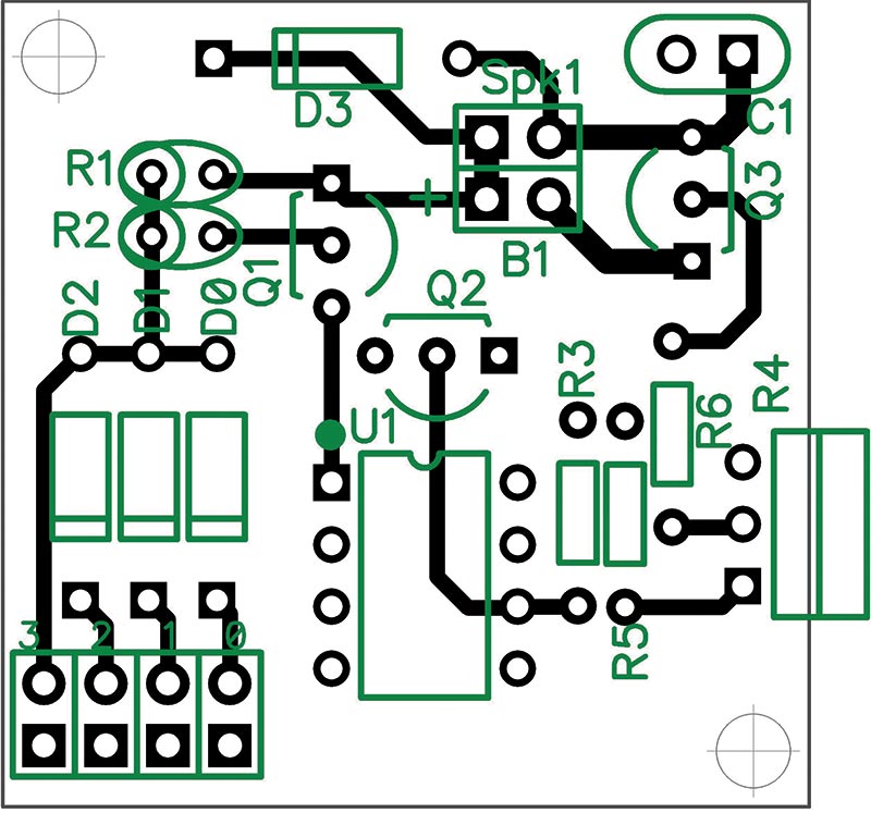
FIGURE 2.
This was done deliberately to keep the high current path of the speaker away from the rest of the circuit.
Note that the current for the speaker does not go through Q1. This was done because I didn’t want the high current to be switched by Q1. My first design had the current go through it, which created a problem. Due to the higher current used by the speaker, the voltage on the output of Q1 varied enough to cause the circuit to function erratically. I would have had to lower the base resistor considerably if I wanted to keep that design.
I found that with the final version of the circuit, I could not measure the current draw with my meter (Fluke 79). I put a 1K resistor in series with the supply and there was less than 1 mV across it. So, the current must be less than 1 µA when the system is off.
All the parts are thru-hole with no SMDs (surface-mount devices). Resistors R1 and R2 were mounted vertically to save board space. The volume control, R4, is mounted close to the edge of the board for convenience and is a vertically mounted trim pot with a “thumb wheel” adjustment. You can mount a horizontal trim pot instead to have a side adjustment.
I mounted the PIC (U1) in a socket, but you don’t have to do that. I used 1N914s for the diodes since I had a supply of them, but almost any signal diode (such as 1N4148s) will do.
As you can see from Figure 3, the board is quite small: 1.3” x 1.3”.
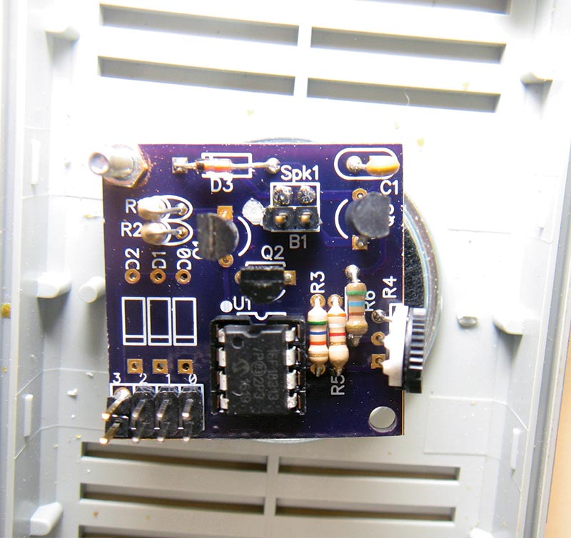
FIGURE 3.
I soldered the wires for the speaker directly to the board instead of using a connector. The white dot to the left of the B1 connector is a score from a silver marking pen (which I always use to indicate the positive connection of the power supply).
The board is light enough that I used a single 2-56 mounting bolt and standoff to attach it to the housing. There is room enough for the three AA cell battery holder above the board. Since jumpers 0, 1, and 2 are not installed, I’m using sequence 0.
Software
The software is very much table-driven. There are three tables that the program uses:
- Frequency of available notes
- The notes to play for a sequence
- Which sequence to play
The table of the notes looks like this:
C4 dw HIGH .137, LOW .137 ;262
D4 dw HIGH .154, LOW .154 ;294
C4 and D4 are the label references for the two notes shown; dw is the assembler directive to store a word or words at the current memory location. HIGH and LOW are the assembler syntax that selects the high byte and low byte of the value to be stored. (Even though the program memory is 14 bits per location, only eight bits can be accessed using memory read commands.) The comments show the frequency of the note for the entry.
The value stored must be the desired frequency multiplied by 0.524, which is due to the accumulator length of the NCO and the frequency of the CPU clock driving it. There are comments in the source code that explain this more fully. The frequencies used in the table for the notes were obtained from https://en.wikipedia.org/wiki/Scientific_pitch_notation.
The table must be completely within the first 256 bytes of program memory. This allows the sequence lists to use a single byte entry for the address of each note to be played. The table can be expanded to cover as many notes as you may need, provided you stay within the 256-byte limit.
There is a conditional assembly directive following the table which will cause a warning message if the table becomes too big. The table can be increased beyond this 256-byte limit as long as you make the appropriate changes in the routine that accesses them, as well as the entries in the table described next.
Within the table is an entry for MC_NOTE. This is the note I use for those sequences for which I have not defined a song or other sequence. The notes I have entered are the Morse Code dots and dashes representing the number of the sequence (1..7) based on Sws 0-2.
The next table contains the lists of notes used for the sequences of the eight possible states of Sws 0-2. This is an example for sequence 0 (Sw3 closed, Sw0..2 open):
Sequence_0 ; Amazing Grace - 1st line
dw D4, QUARTER
dw G4, HALF
dw B4, EIGHTH
dw G4, EIGHTH
dw B4, HALF
dw A4, QUARTER
dw G4, HALF
dw E4, QUARTER
dw D4, HALF
dw 0 ; terminate the list
Here’s the list showing the Morse code notes for sequence 1:
Sequence_1 ; .----
dw MC_NOTE, DOT
dw REST, DOT
dw MC_NOTE, DASH
dw REST, DOT
dw MC_NOTE, DASH
dw REST, DOT
dw MC_NOTE, DASH
dw REST, DOT
dw MC_NOTE, DASH
dw REST, DOT
dw 0
Each list contains two values for each note to be played: the low byte of the address of the note from the previous table, and the length of the note. The length is essentially the number of milliseconds to play the note. The DOT is defined as an EIGHTH and a dash is 3*DOT.
The note lengths are definitions. Only the EIGHTH note has a specific number. All the rest are multiples of EIGHTH. The definition for the eighth note essentially specifies the tempo of the notes being played. The current definition is 0.25 which equates to 250 milliseconds.
The last table contains the addresses of the eight sequences as follows:
Sequence_Table
dw LOW Sequence_0, HIGH Sequence_0
...
dw LOW Sequence_7, HIGH Sequence_7
Upon power-up, the program first initializes the hardware and then reads the switches. It inverts the state of the switches and doubles the value since each entry in the Sequence table is two bytes, and saves it for processing.
The main loop of the program starts by turning on Q2 which latches Q1 on so that even if the doorbell switch is released, the power will stay on. Next, it uses the stored switch value to determine the address of the sequence to play. After playing the sequence, it turns off Q2 allowing power to be removed from the processor if the switch has been released.
The program will execute the main loop up to three times as long as a doorbell switch is closed. If the switch is still closed after the third time, the program lowers the CPU frequency and executes a one instruction loop forever — or until the switch is released and power is removed from the PIC.
The Parts List doesn’t include the batteries (I’m using three AA cells), printed circuit board (PCB), or housing. The battery, speaker and Sw0-3 are set up to use .1” pin headers and sockets if you wish, but they aren’t necessary (and also are not in the Parts List).
PARTS LIST
| Description |
Value |
Name |
Quantity |
| Battery Holder |
|
BC3AAW-ND |
1 |
| C1 |
10 nF |
399-4148-ND |
1 |
| D0, D1, D2, D3 |
1N914 |
1N914BCT-ND |
4 |
| Q1 |
2N3906 |
2N3906D26ZCT-ND |
1 |
| Q2 |
2N7000 |
2N7000TACT-ND |
1 |
| Q3 |
PN2222 |
PN2222ATACT-ND |
1 |
| R1, R3 |
47K |
47KQBK-ND |
2 |
| R2 |
10K |
10KQBK-ND |
1 |
| R4 |
5K |
3352W-502LF-ND |
1 |
| R5 |
4.7K |
4.7KQBK-ND |
1 |
| R6 |
560 |
560KQBK-ND |
1 |
| Spk1 |
8 ohms |
102-3544-ND |
1 |
| U1 |
16F18313 |
PIC16F18313-I/P-ND |
1 |
I purchase most of my parts from Digi-Key since I typically send a check with my order so that shipping is free. If you use this service, please be sure to include any applicable state taxes.
Both the schematic and board layout were done using DipTrace (www.DipTrace.com). There’s a free version available on their website which will handle this circuit quite easily.
So, there you have it. A simple, customizable doorbell. Now, it’s your turn to chime in! NV
If you would like to build this project and want a single board, you can email me at [email protected]. If you want three boards, you can order them directly from OshPark: oshpark.com/profiles/K3PTO.
Downloads
What’s in the zip?
Code Files