There are situations where a low output impedance to headphones is required. This article discusses three different versions of headphone amps to fit your particular application: a stereo amp controlled by the power line; a battery-operated mono amp for a crystal set; and a battery-operated amp for a ceramic cartridge.
A headphone amp is a relatively low-powered amplifier that raises the low voltage audio signal from a source device (be it a turntable, PC, or smartphone) to a sufficient level such that it can be converted (or transduced) into sound waves by the speakers inside your headphones.
The purpose of an amplifier is to receive a small electrical signal and enlarge or amplify it. In the case of a pre-amplifier, the signal must be amplified enough to be accepted by a power amplifier. In the case of a power amplifier, the signal must be enlarged much more; enough to power a loudspeaker.
When do we need a headphone amplifier? There are situations where a low output impedance to the headphones is required.
Modern Mylar diaphragm headphones have an impedance of about 100 ohms. Though some Mylar headphones are very expensive, they can be found for as little as $5. Devices with line outputs require an amplifier to drive the headphones. This includes a CD deck, DVD deck, cassette tape deck, computer output, and any other device with line outputs.
Portable devices such as CD players, DVD players, or cassette tape players already have a low impedance output and don’t need extra amplification.
If you plug headphones into a line output, you’ll hear something, but there won’t be enough power to properly drive the phones. Also, there may be distortion due to the heavy load on the output. You could use an amplifier that is intended to drive a speaker. However, such amplifiers are relatively large and cumbersome for use with phones. Also hum and noise may be heard in the phones which is not noticeable on speakers.
Where line outputs will easily drive a 10K ohm input, there are situations where the input to the headphone amplifier needs to be larger. One such application is a crystal radio.
Traditionally, crystal sets were connected to headphones having an impedance of around 4,000 ohms. With this impedance, the loading on the crystal set was low enough that the set could achieve reasonably narrow bandwidth. Such headphones are no longer available except at a high price as antiques.
With the 100 ohms of modern headsets, it’s doubtful that a crystal set would work at all. So, an amplifier with higher input impedance than 100 ohms as well as a low output impedance is required. Also, battery operation is desirable so that the crystal set won’t be affected by the power line. An application of the past where a high input impedance is required was to amplify the output of a ceramic cartridge in a vinyl record player.
A Stereo Amplifier Controlled by the Power Line
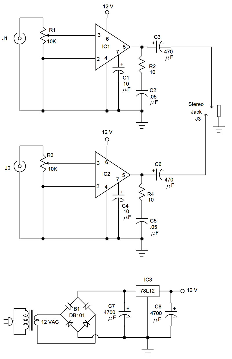
This first of three headphone amplifiers utilizes two LM386 audio power integrated circuits. The chips are designed to supply 300 milliwatts to speakers. The input impedance with the specified volume control is 10K ohms. This amplifier is ideal for connection with line outputs.
For most applications, a voltage gain of one (0 db) is adequate. The voltage gain of the LM386 chip is 20 (26 db), so the volume control will have to be turned down for most applications. The schematic is shown in Figure 1.
| R1, R3 |
10K ohm potentiometer |
| R2, R4 |
10 ohm 1/4 watt resistor |
| C1, C4 |
10 μF 16 volt electrolytic capacitor |
| C2, C5 |
0.047 μF 50 volt ceramic capacitor |
| C3, C6 |
470 μF 16 volt electrolytic capacitor |
| C7, C8 |
4,700 μF 16 volt electrolytic capacitor |
| IC1, IC2 |
LM386 audio power amplifier |
| IC3 |
78L12 voltage regulator |
| B1 |
DB101 bridge rectifier |
| Misc |
Two phono jacks, 1/4 inch stereo jack, 12 VAC transformer, circuit board |
FIGURE 1. Schematic and part list of the LM386 stereo amplifier.
The completed circuit is shown in Figure 2.
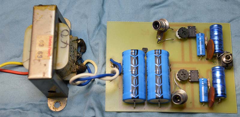
FIGURE 2. The LM386 stereo amplifier.
The printed circuit board (PCB) pattern is shown in Figure 3 along with the parts placement guide in Figure 4. (PCB pattern files are included in the downloads.) This amplifier is powered by a 12 volt transformer. This obviates the need to replace batteries.
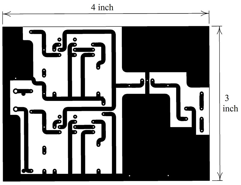
FIGURE 3. PCB pattern of the LM386 stereo amplifier; solder side view.
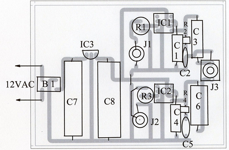
FIGURE 4. Parts placement diagram of the LM386 stereo smplifier.
A Battery-Operated Mono Amplifier for a Crystal Set
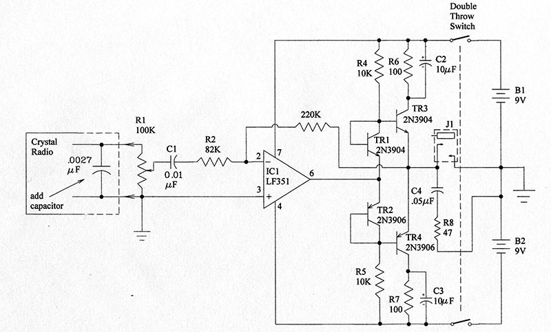
This amplifier has an input impedance of 45K ohms and is powered by two nine volt batteries in order to isolate the crystal set from the power line. The amplifier has a voltage gain of 2.7 (8.6 db), so it will provide higher volume than the old 4,000 ohm phones.
The schematic is in Figure 5. This amplifier uses current mirror biasing which is a relatively new technique. The 100 ohm resistors R6 and R7 are for measuring the current in the output transistors.
| R1 |
100K potentiometer |
| R2 |
82K resistor 1/4 watt |
| R3 |
220K resistor 1/4 watt |
| R4, R5 |
10K resistor 1/4 watt |
| R6, R7 |
v100 ohm resistor 1/4 watt |
| R8 |
47 ohm resistor 1/4 watt |
| C1 |
0.01 μF 50 volt ceramic capacitor |
| C2, C3 |
10 μF 16 volt electrolytic capacitor |
| C4 |
0.047 μF 50 volt ceramic capacitor |
| IC1 |
LF351 op-amp |
| TR1, TR3 |
2N3904 transistor |
| TR2, TR4 |
2N3906 transistor |
| B1, B2 |
Nine volt battery |
| J1 |
1/4 inch stereo jack, DPDT switch, battery holder |
FIGURE 5. Schematic and parts list of the battery-operated mono amplifier.
This amplifier can be used for any application that once required 4,000 ohm phones. The completed amplifier along with a crystal set is shown in Figure 6.
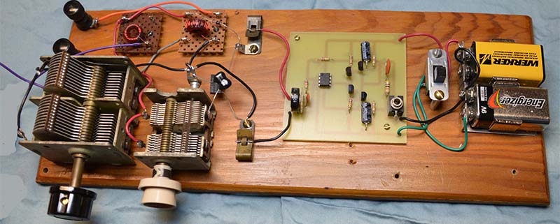
FIGURE 6. Battery-operated mono amplifier with a crystal set.
The PCB pattern is in Figure 7 and the parts placement diagram is in Figure 8.
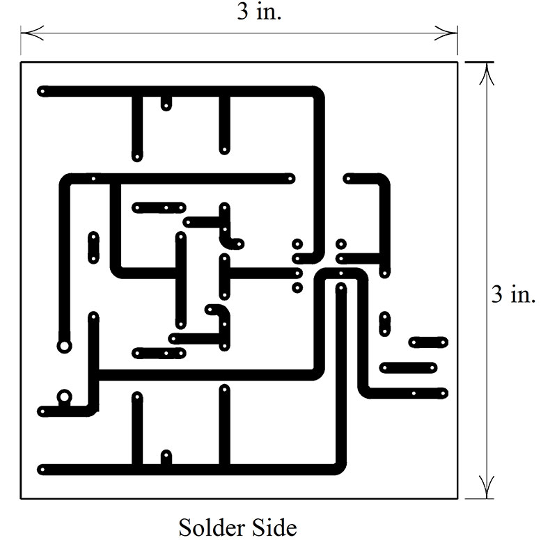
FIGURE 7. PCB of the battery-operated mono amplifier.
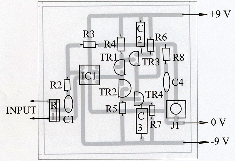
FIGURE 8. Parts placement diagram of the battery-operated mono amplifier.
A Battery-Operated Amplifier for a Ceramic Cartridge
I designed this amplifier in 1959 using germanium transistors, which were the only kind available at that time. The stereo vinyl record became available in 1958. In 1959, not many people had a quality stereo speaker system.
With this simple four-transistor amplifier, a turntable with a ceramic stereo cartridge, and army surplus headphones, you could listen to the “new” stereo records. I still listen to vinyl records with this system to this day.
The schematic of this stereo amplifier is in Figure 9.
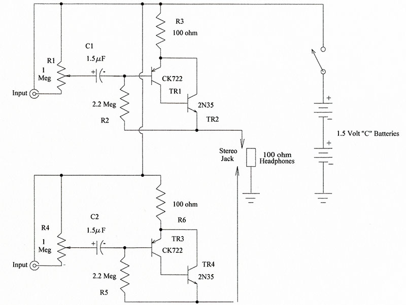
| R1, R4 |
1 megohm audio potentiometer |
| R2, R5 |
2.2 megohm 1/4 watt resistor |
| R3, R6 |
100 ohm 1/4 watt resistor |
| C1, C2 |
1.5 μF 16 volt capacitor |
| TR1, TR3 |
CK722 germanium transistor (may substitute 2N3906) |
| TR2, TR4 |
2N35 germanium transistor (may substitute 2N3904) |
| Misc |
Two C batteries, battery holder, two phono jacks, 1/4 inch stereo headphone jack, power switch |
FIGURE 9. Schematic parts list of the battery-operated amplifier for a ceramic cartridge.
As the two amplifiers draw a current of about 18 mA, they are powered by two C batteries. AA batteries would work but would discharge quickly.
This amplifier puts a DC current (about 9 mA) through the headphones. This was frequently done with the old 4,000 ohm headphones, but I didn’t know if it would work with modern versions. As it turns out, it does work well.
This amplifier has input impedances of 270K ohms. Though it was intended for a ceramic cartridge, it can be used for many of the same applications as the first amp discussed here.
It has a voltage gain of one (0 db), so the voltage of the output can’t be more than the voltage of the input. This is adequate for most applications. The output current, however, is many times the input current. Thus, the amplifier has a power gain.
I recommend building this amplifier using some type of prototyping system. I built it on vector board.
The vector board itself isn’t expensive, but the vector clips that are inserted in the board cost 10 cents each. Nevertheless, vector board prototypes are sturdy and permanent. The vector board prototype is shown in Figure 10.
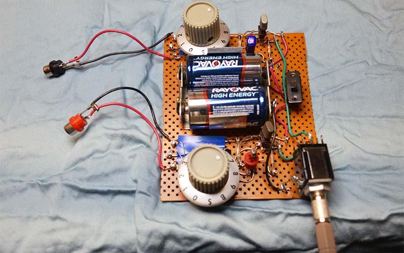
FIGURE 10. Battery-operated amplifier for a ceramic cartridge on vector board.
Conclusion
Headphones can sound better than many speaker systems. When listening to stereo, the “stereo effect” is exaggerated because material that was meant to be separated by speakers is played directly into the ears. Stereo recordings that are intended to be played over headphones are called binaural recordings.
May you have many happy hours listening via headphones. NV