When I was in university, a local restaurant owner approached me about designing a marquee lighting system in his entrance stairwell. He wanted to attract and guide more customers to his business. He never did agree to the proposed price, but it planted a seed. Since that time, I have seen many marquee-based systems at places like local theaters or animated holiday displays.
So, I set out to design my own system based on the following parameters:
- The ability to handle up to six channels.
- No undue stress on the light bulbs by the circuit. The intent here is to ensure the bulbs will last a long time to minimize replacement and system maintenance. A poorly designed circuit will cause early and frequent bulb failure.
- Simple and readily-available components with flexibility for substitutions as needed.
- No computer programming required. The number of channels is determined by a jumper setting on the board; the speed of the lights is controlled with either a printed circuit board (PCB) or an externally mounted potentiometer.
- Through hole components that can be easily soldered onto the PCB.
- Solid-state switching.
- The ability to operate in all temperature conditions.
- Easy testing and troubleshooting.
The end result is my system shown in the Figure 1 photos.
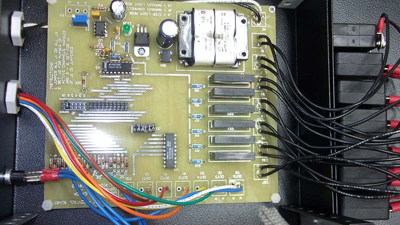
FIGURE 1a. Inside of the control unit.
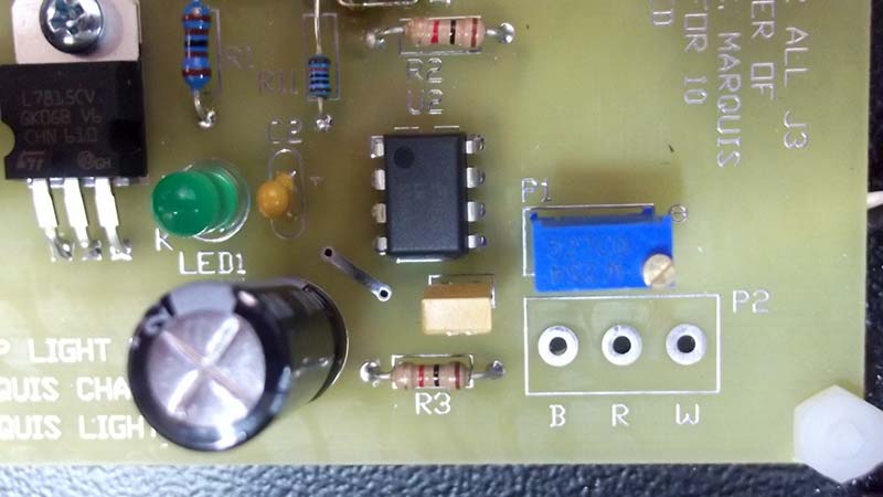
FIGURE 1b. Close-up of the speed control portion of the circuit.
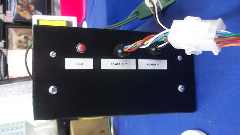
FIGURE 1c. Test button and power plugs.
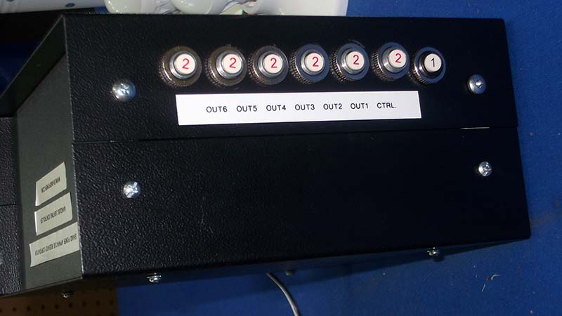
FIGURE 1d. Circuit breaker bank.
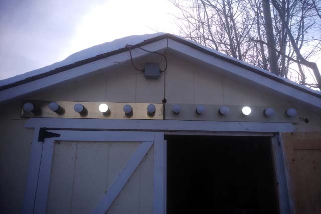
FIGURE 1e. Outside display.
Note: The circuit board shown is a prototype that also does a two head traffic stop light feature (not included in this design).
Important Safety Points to Consider Before You Build this System
- Neither Nuts & Volts nor the author assume any responsibility or liability of any kind as to how you use or install this circuit.
- This circuit operates at 120 VAC, 60 Hz with an unswitched neutral. This is typical for electrical installations in North America. This voltage level can cause property damage, serious burns, injuries, and possibly even death if improperly used.
- All external wiring needs to comply with your local codes and standards. You may require the services of a licensed electrician.
- Power the controller from a supply that has fuses or breakers for overcurrent protection.
- Use of this system is subject to local codes in your area. If in doubt, consult your local electrical inspector for any additional requirements not mentioned in this article.
- While all power components are agency approved (e.g., cRU), the overall system is NOT CSA or UL approved.
- The switching rate must be carefully controlled to prevent triggering epileptic seizures.
THE CIRCUIT AND SCHEMATIC DETAILS
Figure 2 is the schematic of the system.
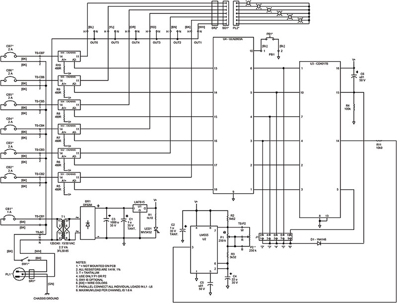
FIGURE 2. System schematic.
Specifics and notes are as follows:
- All resistors are 1/4W 1% metal film. However, published values are not critical, so you can use 5% resistors from your junkbox/lab stash that are close to the published values.
- PL1 plugs into a standard 15A grounded household receptacle. You can wire in an optional single pole/single throw (SPST) switch (SW1) to provide local on/off control of the system. Ensure the green wire connects to the chassis case!
- CB1, T1, BR1, C1, C3, and U1 make up a protected linear regulated power supply that provides 15 VDC control voltage (V+) on the PCB. Because of the board’s low current draw, a voltage dropping resistor upstream of U1 is unnecessary. Also, U1 does not require an additional heatsink. You can substitute a drop-in switching regulator in lieu of the LM7815.
- R1 and LED1 provide control power indication. This is optional; omit these components if desired. You can also externally mount LED1 on the panel.
- U2, C2, R2, P1, P2, R3, C4, and C5 create the astable oscillator section of the circuit. The circuit’s oscillation range is 0.13-4.96 Hz. C2 is a tantalum filter capacitor. I like to use them to minimize any effects from electromagnetic (EMI) and radio frequency (RFI) interference. To adjust the flashing rate, you can use either P1 or P2 but not both. If using P2, something like a Precision Electronics RV4 is a great choice because you can then lock the position of the pot once you’re satisfied with the flashing rate of the system.
- U3 is a sequential continuous counter. R4 and C6 form a “power on reset” function to pin 15, so the 4017 always starts at output ‘zero.’ Diode D1 is then required to interface and isolate the reset function of the counter circuit. The setting of J1 determines the number of active channels on the board by controlling which output the 4017 feeds to its reset pin. Clock pulses from pin 3 of U2 go into pin 14 of U3 via R11.
- U4 is an eight-channel Darlington array driver where the first six outputs are used. Because of the IC’s inverter action, it pulls the solid-state relay terminal A2- to ground whenever a channel is active. PB1 is an optional external test switch that will momentarily turn on all six channels for fast troubleshooting of really large lighting displays. When PB1 is pressed, the unit will draw full load current. If you use the maximum number of 3W LED bulbs as described in the next section of this article, the full expected load will be 9.6A.
- SS1-SS6 are solid-state switching relays capable of handling up to 2A each. The trigger voltage on terminals A1+ and A2- is less than 15 VDC, so resistors R5-R10 provide the necessary series voltage drop. These relays can also switch at a 50 Hz line frequency as well, without any additional changes to the circuit.
- Every channel has a 2A circuit breaker for protection of the relays and the loads against short circuits. Do not omit these components.
- If you need less than six channels, only populate the channels you need for your display starting with OUT1. Example: If you only need four channels, leave out CB6, CB7, SS5, SS6, R9, and R10 on the PCB. Only OUT1, OUT2, OUT3, and OUT4 with their power components and resistors are used.
All components are through hole and mount onto one double-sided PCB measuring 5.4” long x 5.45” wide. The board mounts into a case using four standoff holes sized for 4-40 hardware. Figures 3a and 3b are the board layouts.
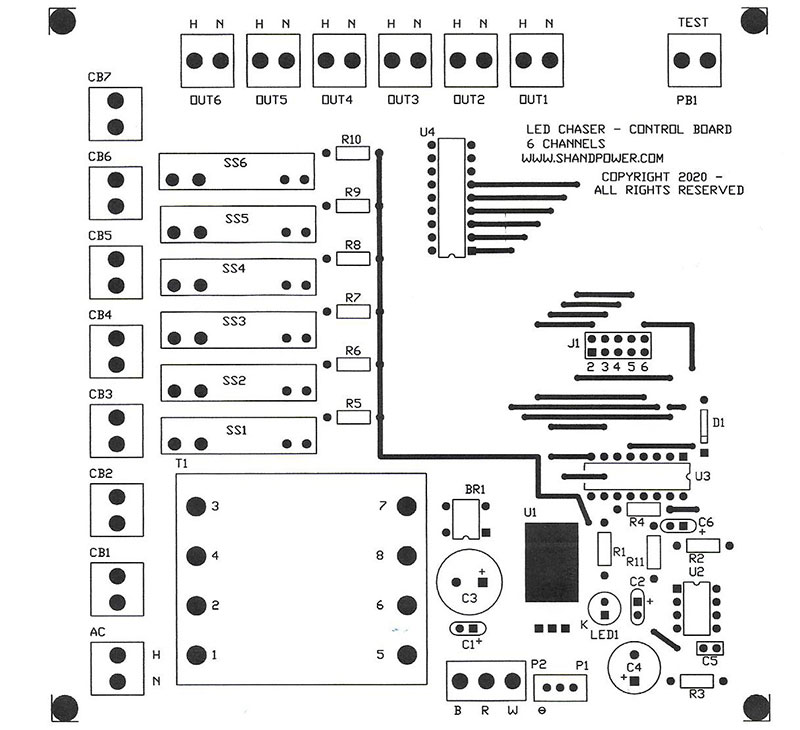
FIGURE 3a. PCB layout top view.
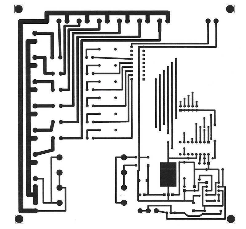
FIGURE 3b. PCB layout bottom view.
The suggested Parts List is for the overall system.
All the components are available from Digi-Key but you can substitute from other sources if convenient/required. You can use optional integrated circuit (IC) sockets for U2, U3, and U4, or you can directly solder them onto the board. U1 mounts to the board with 4-40 hardware.
The Parts List does not include external wiring past PL2, light sockets, lamps, or any supporting means. That’s all up to you and your creativity!
One thing to keep in mind is that the LED bulbs should be “instant on” with no power-up delay from the internal electronics for this system to work effectively.
SETUP & PROGRAMMING
Setup requires some planning on your part. You’ll want to sketch out a plan to determine how you want the lights to flash and then determine the number of bulbs required. My circuit uses 3W LED based light bulbs, and these bulbs are bright! They fit in a standard E26 incandescent light bulb socket.
My prototype used two multiple light bulb bathroom fixtures from a local building recycle store. The relays are capable of handling up to 2A, but I never load a circuit to more than 80% of its rating; 1.6A in this case. Then, the maximum number of 3W bulbs per channel is:
#bulbs
= (0.8 x maximum channel current) / (bulb power rating / 120 VAC)
= (0.8 x 2A) / (3W/bulb / 120 VAC)
= 1.6A / 0.025A/bulb
= 64 bulbs (or a total of 384 bulbs equally distributed over all six channels)
Notes on External Wiring
1. Use proper wiring. Stranded copper with a suitable insulated voltage rating is my go-to. Depending on the length of your runs, you may need to use #14 or #12 AWG wire to keep the voltage drop within values specified by your local electrical codes. This also prevents poor system operation. Some of the bulbs at the end of a circuit may not properly light or even light at all.
2. Use proper materials and components for all external connections and any wiring splices required in the circuit runs. This is not a job for masking/duct tape and thin speaker wire!
3. Wire the channels using color-coded wire to make wiring and troubleshooting easier. I recommend using the resistor color code in the following example:
- a. Channel 1: Black
- b. Channel 2: Brown
- c. Channel 3: Red
- d. Channel 4: Orange
- e. Channel 5: Yellow
- f. Channel 6: Blue
- g. Use green wire for any grounding or bonding requirements. That’s why it’s not used for channel 6.
- h. Use white wire for the neutral. This wire connects to all the light bulb sockets. Observe socket polarity as the white wire must connect to the metallic screw thread
Programming is easy. As mentioned before, J1 sets the number of channels, and P1 or P2 sets the flashing rate. Set J1 with the system unpowered. Adjust P1 or P2 to get the desired switching rate with power applied. Also disconnect the power to the unit before unplugging any loads or changing burned out bulbs. Safety first!
TESTING AND RESULTS
The first prototype test was at an indoor weekend flea market display. For 12 weeks, the display ran for seven hours every Saturday and Sunday. With a switching frequency of 0.5 seconds, each bulb endured over 1.2 million switching operations without any failures.
The second test was at my house and mounted on a front shed as part of a Christmas display. The flashing rate was identical to the flea market setup. The control box sat in the unheated shed in temperatures from -15°F to 40°F. I started the display on the afternoon of November 11 and ran the system 24/7 to January 1 (50 days straight with the exception of two brief power outages). Again, no bulb or system components failed after an estimated 8.6 million switching operations. Both tests used the same bulbs for an estimated total of 9.8 million switching operations.
CONCLUSION
This is the simple, reliable, and cost-effective circuit you need if you’re looking for:
- Creating or re-vamping an old-style theater display.
- Simple lighting animation for displays.
- An application requiring a continuous looping sequence that has to power AC devices.
I hope this circuit really brightens things up for you. NV
Parts List
| ID Number |
Description |
Manufacturer |
Supplier |
Supplier P/N |
| U1 |
Voltage Regulator, 15V, 1A |
Texas Instruments |
Digi-Key |
296-44418-5-ND |
| U2 |
Timer |
Texas Instruments |
Digi-Key |
LM555CNNS/NOPB-ND |
| U3 |
Decade Synchronous Counter |
Texas Instruments |
Digi-Key |
296-2037-5-ND |
| U4 |
Eight-Channel Darlington Driver |
STMicroelectronics |
Digi-Key |
497-2356-5-ND |
| LED1 |
Green LED, 2.2V, 20 mA |
Everlight |
Digi-Key |
1080-1111-ND |
| BR1 |
Bridge Rectifier, 200V, 1.5A |
On Semiconductor |
Digi-Key |
DF02M-ND |
| D1 |
Diode, 100V, 200 mA, DO35 Package |
On Semiconductor |
Digi-Key |
1N4148FS-ND |
| SS1, SS2, SS3, SS4, SS5, SS6 |
Mini SIP Solid-State Relay, SPST-NO, 2A, 24-480V |
Sensata-Crydom |
Digi-Key |
CC1744-ND |
| CB1 |
1A, Single Pole Circuit Breaker |
TE Connectivity |
Digi-Key |
PB193-ND |
| CB2, CB3, CB4, CB5, CB6, CB7 |
2A, Single Pole Circuit Breaker |
TE Connectivity |
Digi-Key |
PB194-ND |
| R1 |
1.10K, 1%, 0.25W Resistor |
Yageo |
Digi-Key |
1.10KXBK-ND |
| R2 |
5.62K 1%, 0.25W Resistor |
Yageo |
Digi-Key |
5.62KXBK-ND |
| R3 |
3.32 K, 1%, 0.25W Resistor |
Yageo |
Digi-Key |
3.32KXBK-ND |
| R4 |
100K, 1%, 0.25W Resistor |
Yageo |
Digi-Key |
100KXBK-ND |
| R5, R6, R7, R8, R9, R10 |
499, 1%, 0.25W Resistor |
Yageo |
Digi-Key |
499XBK-ND |
| R11 |
10K, 1%, 0.25W Resistor |
Yageo |
Digi-Key |
10.0KXBK-ND |
| P1 |
250K Multiturn Potentiometer |
Bourns |
Digi-Key |
3296W-254LF-ND |
| P2 |
250K Panel Mount Potentiometer with Locking Nut |
Precision Electronics |
Digi-Key |
RV4L254C-ND |
| C1, C2 |
1 µF, 35V Tantalum Capacitor |
AVX |
Digi-Key |
478-8953-1-ND |
| C3 |
1000 µF, 35V Electrolytic Capacitor |
Rubycon |
Digi-Key |
1189-3687-ND |
| C4 |
22 µF, 35V Electrolytic Capacitor |
Panasonic |
Digi-Key |
P15802CT-ND |
| C5, C6 |
0.01 µF, 50V Ceramic Capacitor |
Vishay |
Digi-Key |
BC1078CT-ND |
| PB1 |
Panel Mounted Momentarily Normally Open Pushbutton |
E-Switch |
Digi-Key |
EG2011-ND |
| JP1 |
Suitcase Jumper |
TE Connectivity |
Digi-Key |
A26228-ND |
| J1 |
Conn Header Vertical 10-Position |
METZ Connect |
Digi-Key |
1849-1002-ND |
| PL1 |
1.67’ NEMA 5-15P Cord |
Qualtek |
Digi-Key |
Q1054-ND |
| SW1 |
SPST Toggle Switch, 15A, 125V |
Carling |
Digi-Key |
432-1074-ND |
| T1 |
120/240V: 15/30V, 2.5 VA Transformer |
Tamura |
Digi-Key |
MT1121-ND |
| SOCKET1 |
8-Pin DIP Socket for U2 |
CNC Technologies |
Digi-Key |
1175-1475-ND |
| SOCKET2 |
16-Pin DIP Socket for U3 |
CNC Technologies |
Digi-Key |
1175-1488-ND |
| SOCKET3 |
18-Pin DIP Socket for U4 |
CNC Technologies |
Digi-Key |
1175-1478-ND |
| STANDOFF 1-4 |
4-40 x 0.5” Hex Aluminum Standoff |
RAF Electronic Hardware |
Digi-Key |
1772-1545-ND |
| SCREW 1-8 |
4-40 x 0.25” Stainless Steel Screw |
B&F Fastener Supply |
Digi-Key |
H703-ND |
| WASHER 1-8 |
Internal Tooth Washer (for Standoffs) |
B&F Fastener Supply |
Digi-Key |
H236-ND |
| SCREW 9, SCREW 10 |
4-40 x 0.50” Stainless Steel Screw (for U1 and Chassis Ground) |
B&F Fastener Supply |
Digi-Key |
H705-ND |
| NUT1, NUT2 |
4-40 Stainless Steel Nut |
Keystone Electronics |
Digi-Key |
7235-3-ND |
| FLATWASHER 1-4 |
#4 Flat Washer (for U1 and Chassis Ground) |
Keystone Electronics |
Digi-Key |
36-4692-ND |
| SPLITWASHER1, SPLITWASHER2 |
#4 Split Washer for U1 and Chassis Ground) |
Keystone Electronics |
Digi-Key |
36-4693-ND |
| CASE1 |
8” x 8” x 4” Case |
Hammond |
Digi-Key |
HM339-ND |
| SR1, SR2 |
Nylon Cable Gland - PG7 with 8207/8207.40 Nut |
American Electrical |
Digi-Key |
288-1164-ND |
| SO1 |
Nine-Position Socket |
TE Connectivity |
Digi-Key |
A1459-ND |
| PL2 |
Nine-Position Plug |
TE Connectivity |
Digi-Key |
A1458-ND |
| PIN 1-7 |
Pins for SR1, SR2 |
TE Connectivity |
Digi-Key |
A1441-ND |
| PIN 8-14 |
Pins for SO1 |
TE Connectivity |
Digi-Key |
A14300-ND |
| STAKON 1-18 |
Quick Connect Receptacle 14-16 AWG, 0.250” Wide |
TE Connectivity |
Digi-Key |
A27824CT-ND |
| RINGLUG1 |
Circular Ring Connector 16 -22 AWG, #4 Crimp |
TE Connectivity |
Digi-Key |
A0955-ND |
| BLACK WIRE |
#16 Stranded Copper Hookup Wire – Black |
Alpha Wire |
Digi-Key |
A3254B-100-ND |
| BROWN WIRE |
#16 Stranded Copper Hookup Wire – Brown |
Alpha Wire |
Digi-Key |
A3254N-100-ND |
| RED WIRE |
#16 Stranded Copper Hookup Wire – Red |
Alpha Wire |
Digi-Key |
A3254R-100-ND |
| ORANGE WIRE |
#16 Stranded Copper Hookup Wire – Orange |
Alpha Wire |
Digi-Key |
3254OR005-ND |
| YELLOW WIRE |
#16 Stranded Copper Hookup Wire – Yellow |
Alpha Wire |
Digi-Key |
3254YL005-ND |
| BLUE WIRE |
#16 Stranded Copper Hookup Wire – Blue |
Alpha Wire |
Digi-Key |
A3254L-100-ND |
| WHITE WIRE |
#16 Stranded Copper Hookup Wire – White |
Alpha Wire |
Digi-Key |
A3254W-100-ND |
| PCB1 |
Printed Circuit Board |
Shand Power |
Shand Power |
Not applicable |
ACKNOWLEDGEMENTS
I would like to thank the following for their assistance:
Digi-Key
Mr. Greg Whiting, President Alpine Flamingo
Mr. Pierre Dubois, President Circuits Imprimés de la Capitale (www.pcbcic.com/en)
Ms. Tracy Winchester
Downloads
What’s in the zip?
Schematic
PCB Top and Bottom Layers