It's always helpful to have a nightlight to illuminate an area, even if you’ve lived in the same house for 20 years and know where things are. Perhaps the clutter of 20 years has piled higher and crowded into walkways over those years. We’re not going to solve that problem, here.
File This One Under “E” for “Easy”
This project is a motion-activated nightlight. Sure, you can buy these devices already built, but where’s the fun in that? Plus, with the DIY approach, if you want to adjust parameters such as the duration of the light, the color of the illuminating LED, the trigger level for light input, or even multiple motion detectors in different areas, you have complete control.
Let’s Discuss the Hardware
Refer to Figure 1 as we go through the components.
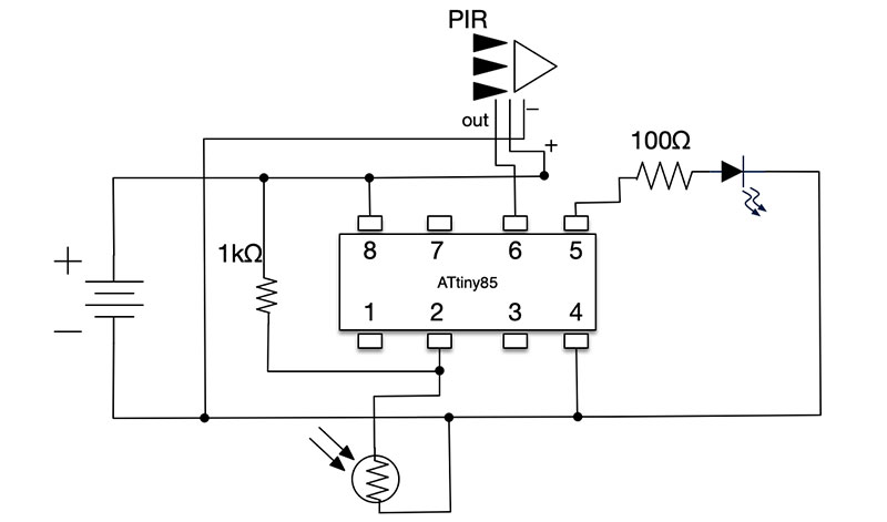
FIGURE 1. Circuit schematic.
Following the principle of using the right tool for the job, I chose the eight-bit AVR RISC-based ATtiny85 microcontroller for this project. The ATtiny85 fits perfectly for this simple project because it’s a low cost chip with just eight pins for easy breadboarding, plus it has a small footprint and relatively low power requirements. You can get it to run at 8 MHz or even 20 MHz, but for something like this, the default 1 MHz is still overkill. (Refer to Resources 1 and 2)
For the motion sensor, I like the Parallax passive infrared (PIR) sensors because they light up to indicate that motion has been detected which you can then correlate with an expected action from the microprocessor which, of course, helps with debugging. If you can find a cheaper model with similar pins, feel free to adjust.
The light sensor is your run-of-the-mill light-dependent resistor (LDR). LDRs have variable resistance depending on the amount of light available: more light means less resistance; less light means greater resistance. To obtain a value of relative brightness, the LDR and a fixed resistor are configured as a voltage divider. This is shown in the connection to pin 2 in Figure 1.
The 1 kΩ resistor limits the current coming from the positive voltage source in case the ambient light is bright and the effective resistance from the LDR is low. Too much current into an ATtiny85 pin will likely have a harmful effect.
As mentioned, when the light is bright, the resistance of the LDR will be low, and most of the voltage in the circuit branch will be “dropped” by the constant resistor, leading to a lower voltage into our ATtiny85’s pin.
So, to trigger the light in darker conditions, we’re looking for a higher input voltage, though the exact level can be adjusted in the code to your personal preferences. In our code, we’ll sample the voltage value and determine whether it meets the criteria for turning on the nightlight LED. (Refer to Resource 3 for an additional discussion on LDRs and voltage dividers.)
Similarly, the LED is your run-of-the-mill LED; though we don’t just turn it “on” for a set period of time. We’ll discuss pulse-width modulation (PWM) shortly. See “Potential Modifications” later in the article for a further discussion on LED choices.
For the power supply, I went with three AAA rechargeable batteries. The ATtiny85 runs at a relatively wide voltage bandwidth — 2.7V to 5.5V — so you have some flexibility in powering this project. As it happened, I had a battery holder for three AAA batteries (I bought a few extra when the local electronics store had a sale) and the approximate 4.5V works for both the microcontroller and the low-lit LED. So, I used that. Of course, if you use higher capacity AA batteries, you’ll get longer performance.
Note: When I first deployed the nightlight, I used brand name disposable AAA batteries and got about four weeks of use from them. Knowing that it wouldn’t make economical or environmental sense to throw out batteries each month, I bought a set of rechargeable batteries. Fresh from the package, I got about three weeks’ worth of power from the rechargeable versions. After fully recharging, I see close to a months’ worth of power before needing to recharge. You may have alternate ideas for powering this project. (Refer again to Potential Modifications.)
As I build more and more projects for actual use rather than theoretical testing on breadboards, I realize more acutely that electronics projects want stability. They want a firm foundation and surroundings that separate and stabilize the components. Also, they want firmly wired connections. So, in addition to the PCB (printed circuit board) for the electronic components (Figures 2 and 3), I also used a project box to enclose the components and attach it to its final location.
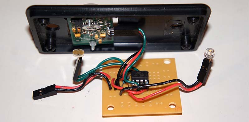
FIGURE 2. Constructed project, showing the individual components and placement. Notice the passive infrared sensor (PIR) on the project box top with small bolts to hold it in place. The light-dependent resistor (LDR) is the component center-left with the wavy lines. Female headers simplify component connection.
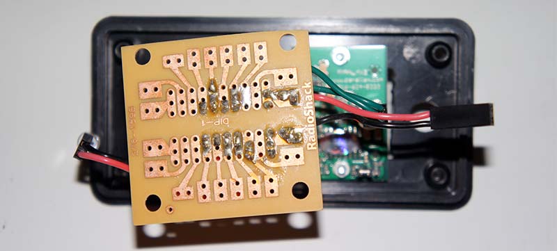
FIGURE 3. Underside of the circuit board, showing the convenience of connecting the various components to the separate pads.
Take a look at Figure 4.
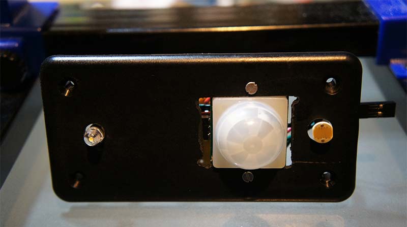
FIGURE 4. Top of the constructed project box, showing the position of the LED, PIR (white dome), and LDR (wavy lines).
You don’t have to use a project box, but it makes things easier and somewhat cleaner looking. For my project box, I “eyeballed” the approximate locations for the LDR and the LED which must have visibility outside of the box, and then drilled holes for them.
The hookup wire I used is solid core which generally holds its shape when bent, so the components are easily positioned where I want them.
The only component that needed screws was the PIR. A couple of thin bolts and compatible nuts worked just fine. You can use my project box arrangement as your own or come up with a completely different layout.
Software Logic
The pseudo-code logic of this project is about as simple as you could imagine:
- Wait for motion detected.
- If the light sensor reads above a certain value (if it’s dark enough), turn the LED on for three seconds.
- Resume waiting for motion.
We’ll discuss each of these portions individually.
Wait for Motion Detected
We have no reason to do anything of interest until we have motion, so in the block waitForMotion() in the code, we loop eternally, reading the PIR pin every quarter of a second until the PIR senses motion and sets the pin high (logical 1). At that point, we exit the loop so we can turn the LED on. This “loop eternally” is what we call “blocking.” Nothing else happens on the microcontroller until we get a desired signal.
Check the Ambient Light Level
As mentioned previously, the voltage divider will read a higher value when there’s less light because the LDR presents such a high resistance value in the dark and drops the majority of the voltage in the divider. The loop() function in the source code will read the analog value from pin 6 in Figure 1, scale it down to a 0-255 value, and then compare it against an arbitrary threshold. The threshold is defined as:
int lightThreshhold = ( .80 * 255 );
or 80% of the range. The higher you set the threshold, the darker it has to be to turn on the LED. You may want to change this if you find that the LED is on too often or not enough.
Turn On the LED for Three Seconds
The LED is “turned on” using PWM, which is amply described in Resource 4. In short, the LED is turned on and off quickly — faster than the eye notices — to allow us to dim the LED as if we had a variable brightness bulb.
As this is a nightlight and not a flood fill spotlight, we don’t necessarily want the full brightness of the LED. The brightness and duration of the light are both adjustable in the program code; see the function turnOnLed().
Once we’ve turned the LED on for the time limit, we return to the blocking loop to wait for more motion. It might be that motion is on-going, in which case, the blocking loop will immediately return to enable the LED again. Until the battery runs out, this is all we do.
Writing the Software
I used the Arduino application to write the software for this project. Arduino, of course, was designed to make microcontrollers accessible to the rest of us. I’m not going to provide an in-depth discussion of the Arduino project. That’s available on the Arduino project page; see Resource 5. If you don’t already have the Arduino app, you can download it from the link included in Resource 6.
Once you have the Arduino application installed, you’ll need to enable ATtiny85 support within, if you haven’t already. The Arduino environment supports many microcontrollers and related boards. By default, ATtiny85 support isn’t provided, so you need to add it. Fortunately, it’s relatively simple.
Rather than recreate the already well-written instructions from the Arduino project, I’m going to simply refer you to the page that explains how to do this; see Resource 7. When done, your Arduino configuration should look like Figure 5.
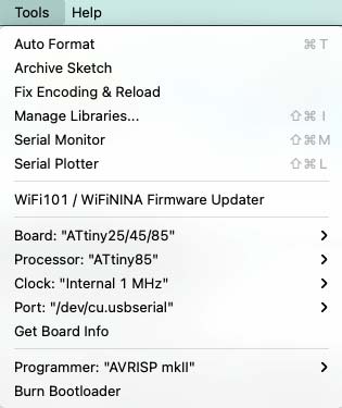
FIGURE 5. Arduino application configuration parameters when we’re ready to compile the program for the ATtiny85.
Take special note of “Board:,” “Processor:,” and “Programmer:,” which is discussed further below. “Clock:,” by default, is “Internal 1 MHz.” You can push the ATtiny85 faster, but it won’t improve performance in this application.
At this point, you should have the Arduino application installed; board support for the ATtiny85; and the correct microcontroller selected for the “Board.” We’re almost there. You can now load the MotionSensorNightLight_V03.ino code into the Arduino application.
From within the Arduino, use the File → Open option and browse through your folders to where you downloaded the project .ino file, then select that. It should open the source code in a new page. The code has been tested on my machine and should work right out of the box.
To compile, click on the “Verify” button in the upper left of the Arduino window; it should look like a checkmark (Figure 6).
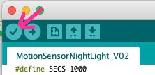
FIGURE 6. Button to press to compile the project within Arduino.
If all goes well, you should see a report in the bottom of the Arduino window that says, “Done compiling,” and a summary of how much memory the sketch uses.
Programming the Controller — Hardware
The results of compilation — assuming no syntax errors or typos — is a hex file which needs to be downloaded to the ATtiny85 before it can be executed. Unfortunately, it’s not just a simple drag-and-drop type of copy. The ATtiny85 requires specific signals on specific pins at certain times to successfully copy the hex file. Yes, it’s tricky, but it’s a solved problem.
Given that Arduino has a vast community of do-it-yourselfers who have done it and then some, there are plenty of options for writing the hex file to the ATtiny85. However, I decided to go with the official Atmel AVRISP mkII. This is a device built and dedicated to programming AVR chips. I was able to find these on Amazon (see Programmer Options below). It should cost less than $50, and it will save you lots of time and hassle when programming your AVR microcontroller.
You might also find one on eBay, but buyer beware. Alternatively, if you get serious about AVR programming, there’s the newer, more expensive — but with broader programming abilities — Atmel-ICE. It’s the replacement for the mkII, but, as mentioned, more expensive.
Programmer Options
I haven’t used the SparkFun or Pololu devices, but they seem to be drop-in replacements for the mkII. The under-the-hood programming software — avrdude, if you’re interested — is the same.
Wiring the Programmer
See Figure 7 for an example of how I configured the mkII to write the hex file to the ATtiny85.
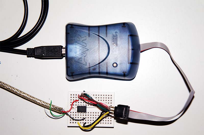
FIGURE 7. Components needed to download the hex file to the ATtiny85.
I’ve also included Figure 8 to clearly identify the wiring from the mkII to the actual pins on the ATtiny85.
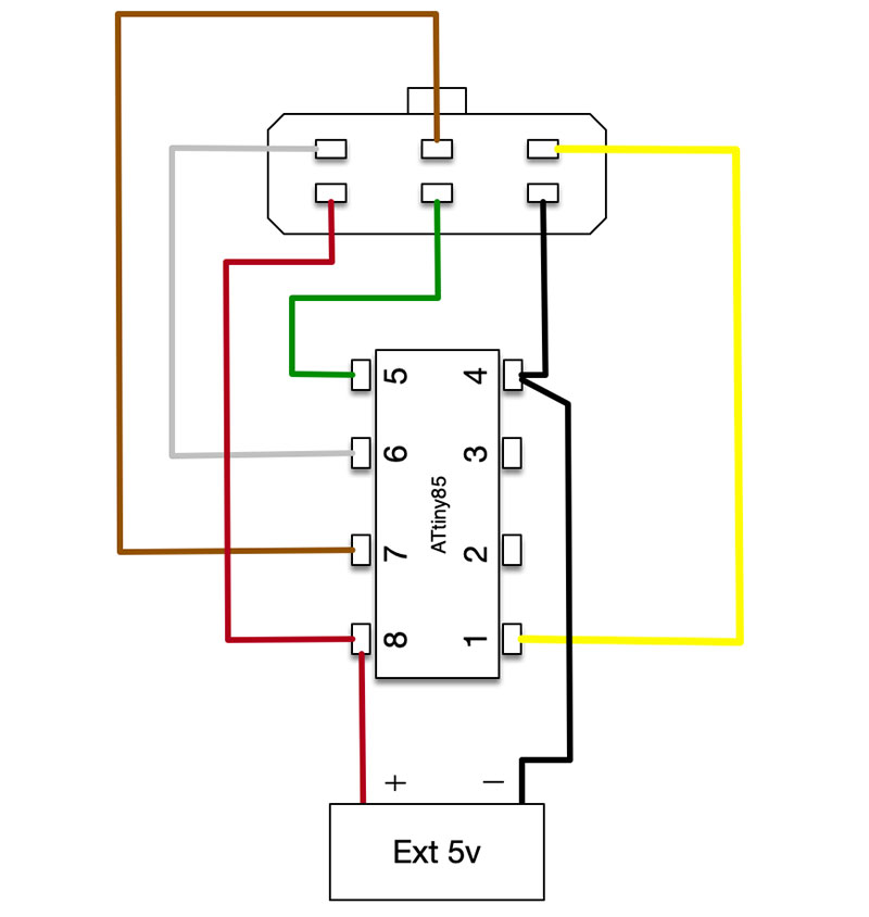
FIGURE 8. Detailed wiring connections coming from the AVRISP mkII connector.
You can program the ATtiny85 “in circuit” if you can wire it properly. However, you’ll have to make sure some pins in the circuit are not connected during programming, so they don’t interfere with the needed SPI signals.
As such, I figured it was easier to program the ATtiny85 on its own little programming breadboard and then put the chip in the socket on the PCB. If you don’t make lots of repeated modifications, it shouldn’t be too tedious to program the chip like this.
Note – very important: The AVRISP mkII requires an external power supply of approximately 5V into the pins of the ATtiny85. I’ve banged my head more than once on the little orange status light on the mkII because I’d neglected the external power. You’d think the mkII would provide the power for the chip, but it doesn’t.
If you try to program the ATtiny85 and simply get a blinky orange indicator, you need to supply power. That’s the “Ext 5v” in Figure 8. I hacked an old USB cable to expose the 5V and ground lines to provide an easy power supply.
Programming the Controller — Software
When programming from the Arduino interface, DON’T use the “Upload” button; use Sketch → “Upload Using Programmer,” instead as shown in Figure 9. If you’re using the AVRISP mkII device and it’s connected properly (including the external 5V supply), you’ll see the mkII status light go from steady green to flickering orange, and then steady green again.
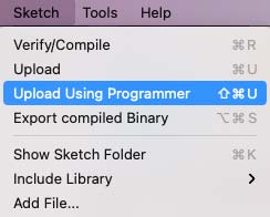
FIGURE 9. Correct Arduino program option to download the hex file to the ATtiny85 through the AVRISP mkII.
Once the mkII is showing steady green, the chip has been programmed and, if you’ve programmed it separately from the circuit, you can remove it from your programming breadboard and install it in the circuit. Build your circuit; provide power; and your nightlight should now be operational.
Installation
We sometimes have to get up at night to use the bathroom, so I chose a spot on the ceiling of our bedroom near the corner of our bed and also near the door to the hallway to install the nightlight (Figure 10).
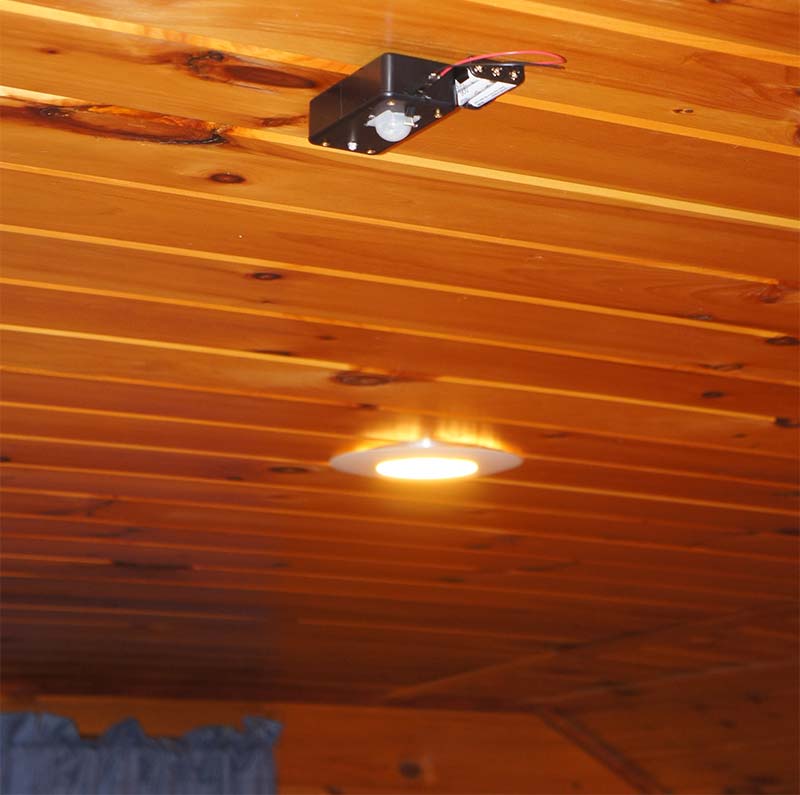
FIGURE 10. Example of positioning the nightlight in its final location.
The motion sensor is close enough to the bed that when we move our feet, it triggers the nightlight giving us a small amount of light to see our way to the door. The light, itself, however, is far enough away that we don’t notice it in our sleep if we’re just moving under the covers and accidentally trigger the motion sensor.
The LDR should protrude enough from the case to adequately sense the ambient light or it’ll trigger constantly. You may want to position the LDR side of the project box toward a window to optimize the light input to the sensor. Similarly, the LED should protrude from the project box so that it provides maximum lighting.
With my project box, I had to install the “top” piece first, screwing that into the ceiling, and then screwing the lower portion to the anchored top; see Figure 11.
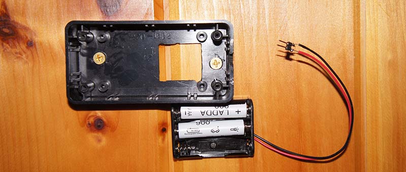
FIGURE 11. Project box top anchored to the ceiling. The box base with the project components will attach to the box top.
Of course, you’ll want to observe all household electrical safety precautions! For example, don’t drill screws into existing wiring runs above the ceiling, etc.
Potential Modifications
I used a white LED in my version, but a red, green, or blue one might be more palatable for different situations. For example, and related to the next item, a brighter white LED might act as an irritant while you’re sleeping if you’re using the nightlight in your bedroom.
The motion sensor can be triggered by adjusting the covers, depending on the distance away from the sensor. If you can’t set the PWM level to something low enough to be useful but not too bright to wake you up, try using a red or green LED instead.
Those colors might have less of an effect on your eyes while you’re sleeping. If you use female headers to attach your LED like I did (see Figure 2), then changing LEDs should be pretty simple. Just remember to match positive and negative polarities.
Initially, I had the LED brightness set for 25%, but my wife found that a little too bright, so I changed it to 20% instead. You can adjust the output as you like.
The code for this is located in:
#define PWMPULSEWIDTH 0.20
Power Supply
As mentioned above, I went with three AAA rechargeable batteries for simplicity, but you could also use a cheap USB power supply with a long enough cable. The 5V from the USB adapter is plenty. That way, you’d never have to change batteries which might be very useful, depending on where you position the motion detector. The circuit draws very little power, so adding a solar panel (depending on solar availability) would be an interesting upgrade. If you go this route, tell us about it.
One Last Idea
You could, theoretically, string a PIR sensor further away from the LED and processor, or more than one PIR sensor; refer to Figure 12.
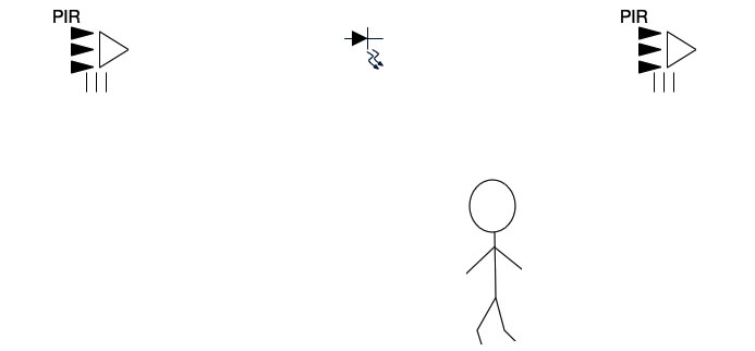
FIGURE 12. Potential arrangement of multiple PIR sensors with a single LED in a longer hallway.
Let’s say you have a long hallway and you want to extend the coverage of a single unit rather than install multiple units.
You could build the circuit as shown, but instead of positioning the PIR sensor right next to the ATtiny85 and LDR (as in Figure 2), you could run wires some distance down the hall and trigger the PIR sensor before you reach the LED.
This would be a case for a brighter LED setting as well. There are two free pins on the ATtiny85 in this design that you could use for additional PIR sensors. You’d need to modify the code to include them in the motion checks, but that’s relatively simple.
Summary
This project used parts that I had sitting around. It was easy enough to implement in a short amount of time and filled a minor need. Additionally, it was fun and taught me something new. If you’re a parent or grandparent of inquisitive children, you could use this as a teaching project.
When I first started to write this, it seemed “easy” to me. Now, having explained all this, I’m not so sure. NV
Downloads
What’s In The Zip?
Code File