What could be more fun than building a miniature oscilloscope? Not one with an LCD screen, but a scope with a real live cathode ray tube just one inch in diameter. All the parts — including two 6AU6 vacuum tubes — will be housed in a 5” x 7” x 2” box.
My inspiration came from the cover of a 1960 issue (Figure 1) of Popular Electronics.
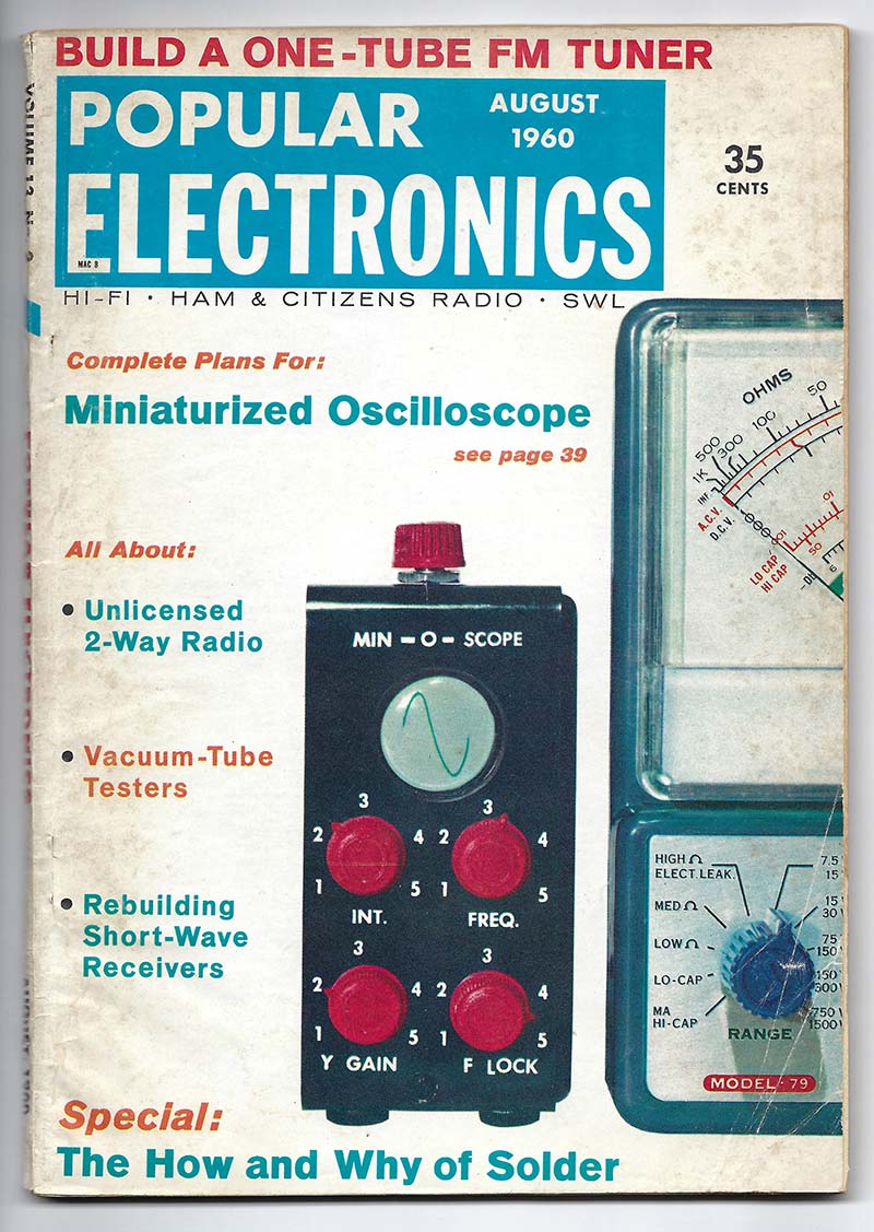
FIGURE 1. The inspiration for the one inch scope project was the Min-O-Scope featured in the August 1960 issue of Popular Electronics.
Actually, over the years, a bunch of clever people have built similar scopes using one inch CRTs. I decided to use the circuit in the magazine to see if I could build one just like Mr. Schauers W6QLV did way back then, with maybe a few changes and improvements thrown in.
The original Popular Electronics article can be found at https://worldradiohistory.com/Popular-Electronics-Guide.htm in the August 1960 issue, pgs. 39-44. It has some classic assembly diagrams that were popular in that era — much like the beautiful assembly drawings for Heathkits.
THE BIG REVEAL
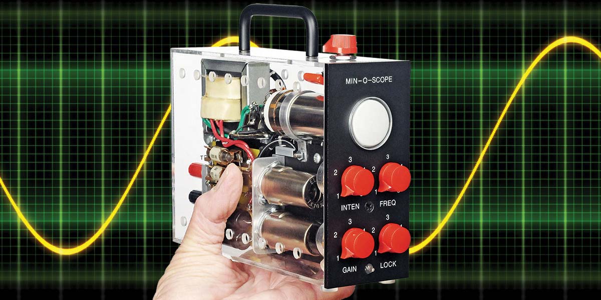
Figure 2 shows the finished scope and Figure 3 illustrates various signals displayed on its screen.
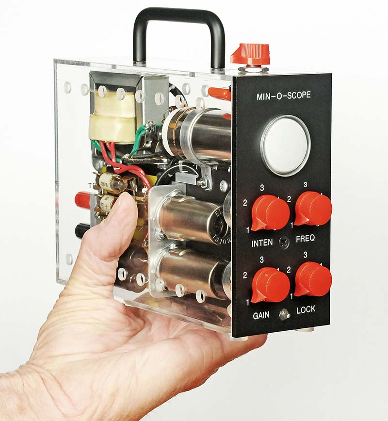
FIGURE 2. I housed the scope in a clear plastic case to showcase the vintage components such as vacuum tubes and cartridge rectifiers.
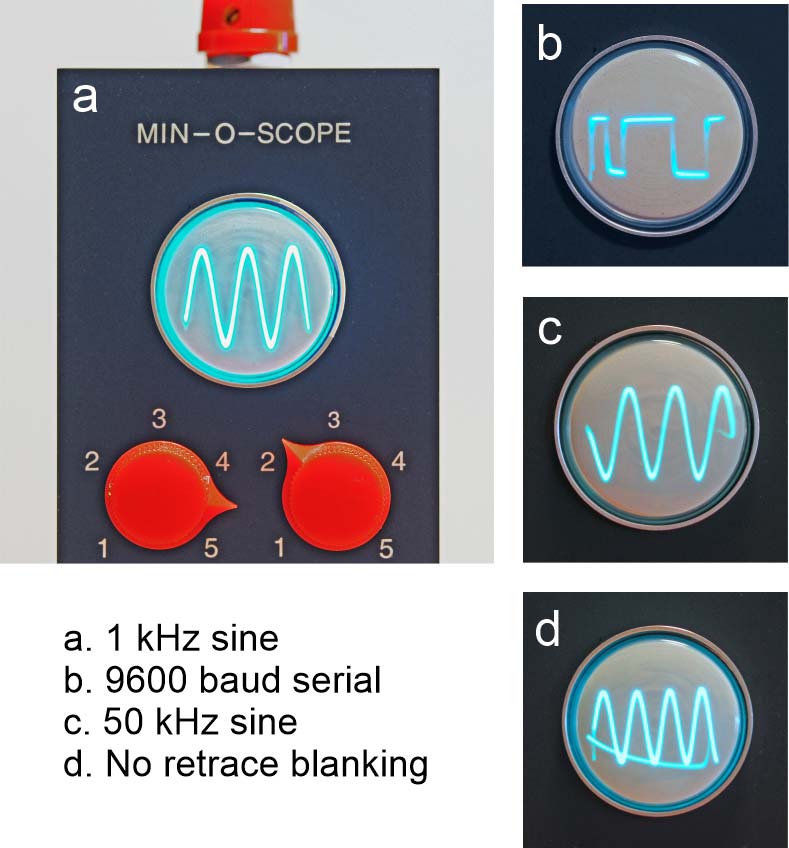
FIGURE 3. The compact unit is handy to check audio signals and digital data streams up to 19,200 baud.
As you can see, I opted for a clear plastic case because I thought it would look cool. Several lines of vent holes allow air circulation for the heat from the filaments of the vacuum tubes and the circuitry.
Signal B in Figure 3 is the serial output of an Arduino. I find this little scope handy to check audio and digital outputs of projects — especially when I’m just starting to check them out. Of course, it can’t compete with larger scopes, but what can you really expect from a “one inch” wonder.
The red knob on the top is a four-position rotary switch that controls the basic SWEEP speed. The pot on the front panel, marked FREQ, is the fine control. The LOCK control even does a fair job of syncing the sweep to the signal. However, you’ll have to play with all the controls to optimize the trace. It’s not like the perfect traces on a Tektronix or HP.
PERFORMANCE
The performance is what you might expect from a scope that has just two 6AU6s to do all the work. The horizontal sweep rate is set at 60 Hz to 18 kHz in four steps. This range can easily be modified by changing the sweep capacitors, within limits. The fine FREQ control has a range of 5-to-1.
The vertical sensitivity is pretty good. At 1 kHz, a three volt peak-to-peak sine wave will result in full vertical deflection. A 200 mV input produces a very usable 1/10” high waveform on the screen. With the GAIN control at maximum, the response is flat to 60 kHz and falls off to one-half at 300 kHz. Digital signals look good out to 19200 baud. Beyond that, they round off.
There’s no reticle on the screen at the moment but that seems like something that could be explored, along with calibration of the horizontal and vertical controls. Maybe in the future.
Bottom line: When you need a quick look at an audio or moderate rate digital signal, this scope can do the job.
THE SCHEMATICS
Figures 4 and 5 and the supporting Parts List reflect my final configuration.
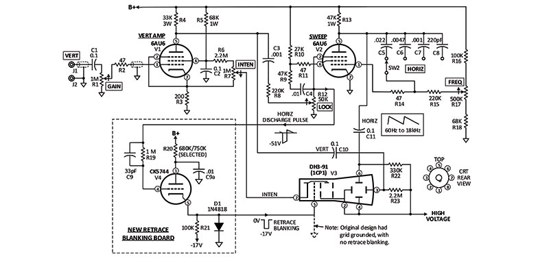
FIGURE 4. The sweep rate is 60 Hz to 18 kHz in four steps, along with a fine FREQ control. A new retrace blanking circuit was added.
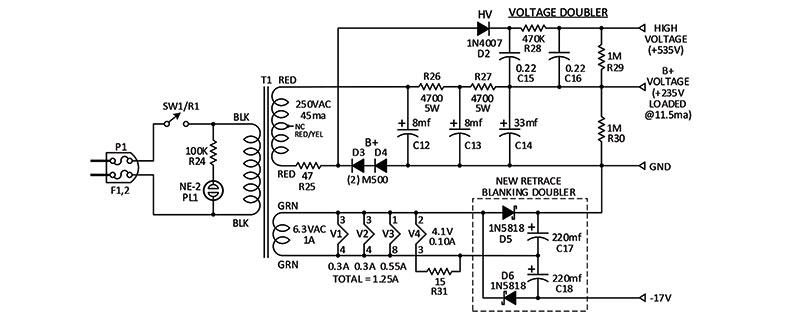
FIGURE 5. The power supply has two voltage doublers to generate special voltages for the CRT and blanking circuit.
The changes I made will Wbe described shortly in more detail. Before moving on, I’d like to mention a few things about the circuit design.
The power supply circuit is a little unusual in that the rectifiers (D3, D4) are in the ground leg of the B+ supply instead of up near the first filter capacitor C12. The original designer did this to produce a common ground for the B+ supply and the high voltage doubler circuit for the CRT. Actually, it’s a fairly clever design although the charging path for the high voltage capacitor C15 has to go through R26 and R27, which tends to buck the B+ supply. This interaction adds a 200 mV P-P ripple to the B+ supply, which is not significant because the B+ is 235 volts.
The other voltage doubler (which I added) is connected to the 6.3 VAC filament winding and supports the new retrace blanking circuit. The original design didn’t have any blanking and the retrace line was very distracting on the display.
Here’s a quote from the original article explaining how the vertical amplifier and sweep circuits work:
“Vertical deflection amplifier V1 is a conventional resistance-capacitance-coupled amplifier. The input signal from J1 is fed through DC blocking capacitor C1 to potentiometer R1, which controls the gain of the stage and thus the height of V3’s displayed pattern. The omission of the usual cathode-bypass capacitor from V1 introduces degenerative feedback into the stage and thus extends frequency response.
Sweep oscillator V2 generates the sawtooth waveform required by V3. Although V2 appears to be another conventional class A amplifier, the stage is actually a modified Miller integrator circuit. Its sawtooth output is chiefly a result of capacitors C5 through C8, which are individually switched between V2’s plate and control grid. The input to the tubes suppressor (controlled by the setting of R12) governs the charging and discharging of the selected capacitor by alternating V2’s effective plate and screen voltages; potentiometer R17 varies sweep speed over a 5-to-1 ratio by adjusting the voltage applied to the grid of V2 in its class A state and thus the discharge rate of the selected capacitor.”
LOOKING FOR VINTAGE HARDWARE
The first task was to find a source for the critical 1CP1 CRT; eBay, no joy. The usual vintage tube suppliers were also a no-go. However, I saw a reference to a Mullard DH3-91 that was compatible with the 1CP1. Back to eBay and bingo! $34 plus shipping from the UK. I ordered two, in case I dropped one. I checked eBay again and there was a genuine 1CP1 in the UK for $53. Oh well.
The 1CP1 and DH3-91 have interesting bases; eight pins loctal. Not octal, loctal. The pins are thinner than the usual eight-pin octal tube and there is a fat center pin that “locks” into a mating socket. The loctal configuration was developed in the 1950s for car radios so the tubes wouldn’t vibrate loose. I was pleasantly surprised to find a vintage loctal socket in my junkbox. You never know when something might come in handy in 20 or 30 years.
The Mullard CRT is self-focusing which helps reduce the parts count. Centering of the trace is controlled by the values of R22 and R23, thereby reducing the need for additional pots.
The other critical component to find was the power transformer, which I had grave doubts about. But … it took just one click on Antique Electronic Supply (tubesandmore.com) to find the perfect match: 250V at 45 mA and 6.3V at one amp. Plus, it was almost exactly the same size as the transformer used back in 1960. I was amazed!
THE BREADBOARD
Now I felt confident that I could move ahead with finding the rest of the components on Mr. Schauers’ parts list. For example, I wanted the resistors to be vintage Ohmite “Little Devils” with their bright unambiguous color bands. Luckily, I already had a fairly good stock of Little Devils, but I did have to go through them because as you probably know, carbon resistors tend to drift with age.
Admittedly I did make a big exception with “vintage-ness” by going with modern capacitors. It was easier to use the slick yellow 630V capacitors from Antique Electronic Supply than to search for ceramic or paper parts. So, sue me.
Figure 6 is an early photo of the breadboard I built to double-check the design.
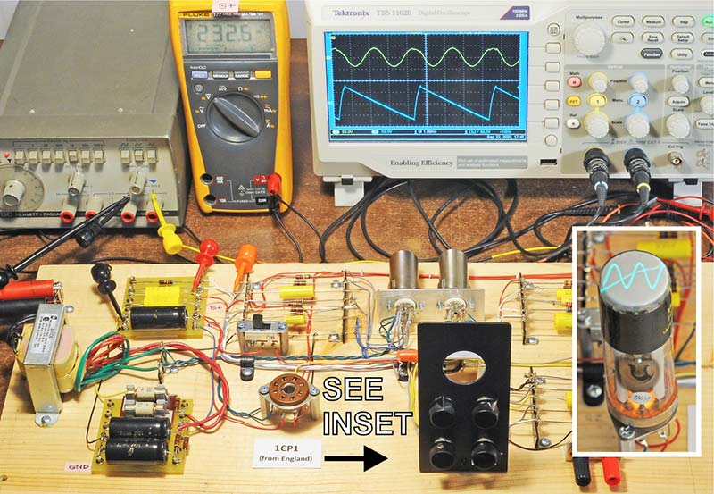
FIGURE 6. A full-up breadboard allowed testing and resolution of several problems prior to packaging.
I’m glad I spent the time to build it because it would have been a disaster to cram all those parts in a tiny box and not have it work for some reason(s). Amazingly, the breadboard worked the first time I powered it up, but as time went on and the CRT arrived from England, I discovered several problems that needed attention.
PROBLEM #1: The horizontal sweep did not always start when the breadboard was turned on.
Analysis: After checking the wiring and values of all the components, they looked okay. What the heck?? I went back and reread the writeups by other people who had built similar 1” scopes. Nada.
Solution: I did what all good service technicians do: plugged in a new tube. Success!!!! Grrrr!
Comment: Initially, I had checked six vintage 6AU6s on my tube checker and they all tested in the green. The one I started with showed 86 on the meter and didn’t work in the sweep circuit. The one that worked had a reading of 106. Whatever!?
PROBLEM #2: After days of exercising the breadboard, the B+ voltage suddenly went to zero.
Analysis: The M150 rectifier (now D3 and D4) was open. Fortunately, it didn’t short! It was rated at 150 mA and the whole scope only drew 11.5 mA. The peak reverse rating (PRV) was a different story, however.
Comment: This problem prompted me to take a hard look at the power supply design. Figure 7 shows what I concluded.
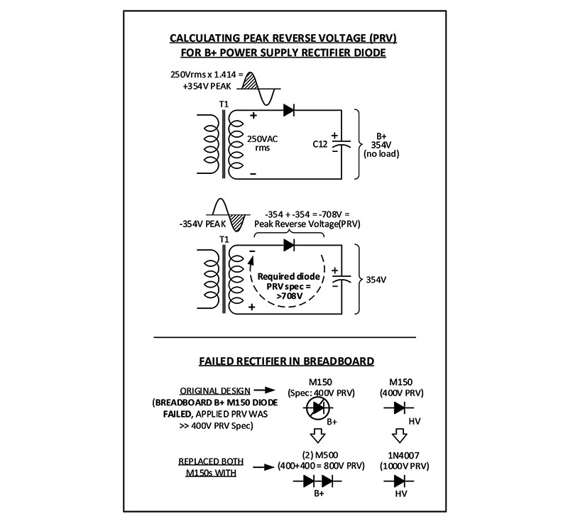
FIGURE 7. The original design overstressed the rectifiers in the power supply, requiring a change to higher PRV rated rectifiers.
The B+ rectifier was vastly underrated for a “capacitor input” power supply. In this type of supply, the rectifier must have a PRV of at least TWICE the peak output of the transformer. The M150 was rated at 400V and approximately 700V was being applied, so it failed.
Solution: I wanted to keep the neat looking cartridge-mount rectifiers, so I snapped in two Sarkes M500s (D3, D4) in series as an upgrade to the M150 that failed. (Jumping ahead, if you look closely in Figure 11, you can see a 1N4007 [D2] tucked in near the M500s that replaced the other M150 diode.)
PROBLEM #3: Each time the scope was powered up, I could smell something cooking.
Analysis: I gave each component the finger test and zowie! The 33K resistor (R4) practically melted the ridges off my finger. It was a 1/2 watt resistor dissipating 3/4 watts. The original parts list specified using all 1/2 watt resistors. However, R5, R13, R26, and R27 were pretty hot too, so I measured/calculated the actual dissipation of all the resistors.
Solution: Only five of them were being overstressed. They were replaced with higher wattage components. Some replacements were a bit overrated only because I had them on hand.
PROBLEM #4: It was distracting to have the visible retrace of the CRT beam cut across the screen. Please see Figure 3d.
Analysis: Several other similar small scopes had blanking amplifier circuits which usually required yet another vacuum tube. I had very little room to spare.
Solution: After puttering around for several days, I designed a blanking circuit that used a Raytheon subminiature CK5744 triode. I also had to add a doubler circuit to generate a negative 17 volts to turn off the grid of the CRT during retrace. The CK5744 acts as a high-to-low impedance switch, with a frequency boosting cap (C9).
PROBLEM #5: The total filament current required for the 6AU6s, CK5744, and CRT added up to 1.25 amps which was 25% higher than the one amp rating of the transformer.
Solution: Live with it, since this was a hobby project; not something for a man-rated rocket. Plus, the 250 volt winding was underused, so the total VA rating of the transformer was not exceeded.
QUESTION: What the heck is with all the 47 ohm resistors? I think the only necessary one is in the power supply. In the past, a low value series resistor (R25) was recommended by the manufacturers of M150/M500 cartridge rectifiers to reduce inrush currents.
TIME TO PACKAGE ALL THE SUBASSEMBLIES
First of all, let’s talk about the clear plastic box. On the Internet, I found a number of suppliers of plastic display cases. The stock sizes were pretty cheap and it was just a bit more for custom sizes. I ordered two cases for $77 each because I knew from experience that I could easily mess one up when drilling the holes.
As you know, drilling holes in brittle acrylic plastic is tricky at best. So, I purchased a set of special drills made just for plastics. Their cutting faces were specially shaped, so they didn’t grab the plastic.
They worked great at 300 RPM on the milling machine. Not a single hole cracked or crazed. There are videos on YouTube on how to modify regular twist drills for drilling plastics or brass.
Figures 8 and 9 show the interior of the original unit, as published in the 1960 magazine.
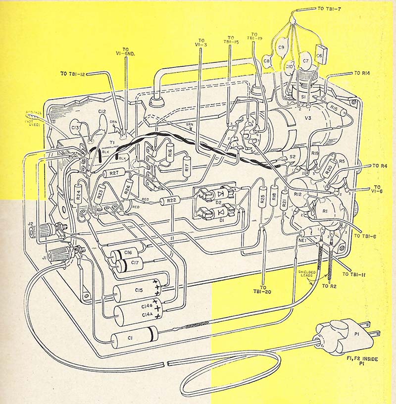
FIGURE 8. The assembly drawings in Popular Electronics were beautiful but depicted an unruly nest of floating components.
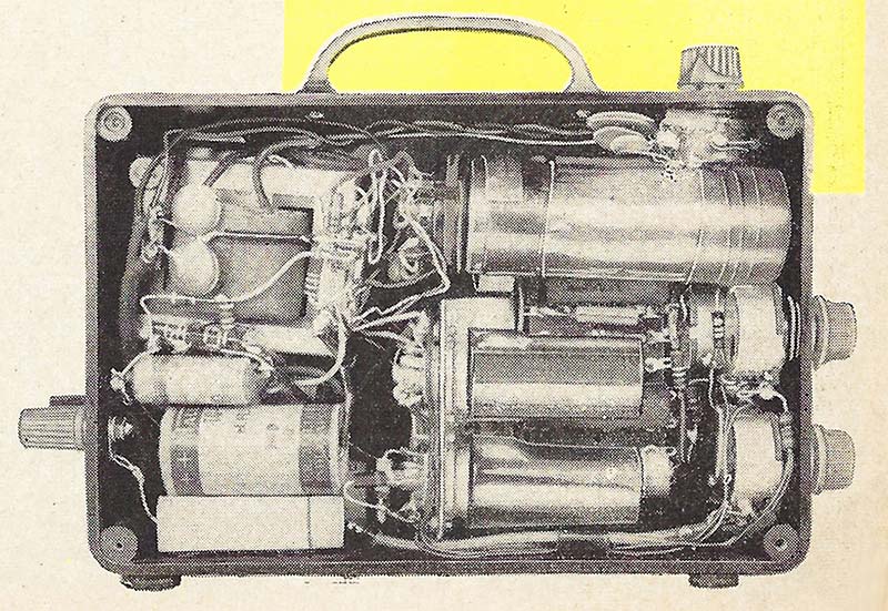
FIGURE 9. A photo of the original Min-O-Scope showed a good general layout, but could have employed a neater wiring job.
The builder’s technique of mounting most of the components with flying leads was way too messy for me.
So, I went back to Antique Supply and found some “yellow tagboards” that looked like they could be used to clean up the mess. I could have fabricated custom “turret” boards which would have been more compact but the stock tagboards were close enough.
Figure 10 shows an exploded view of all the finished subassemblies including the neat power plug with its two internal fuses.
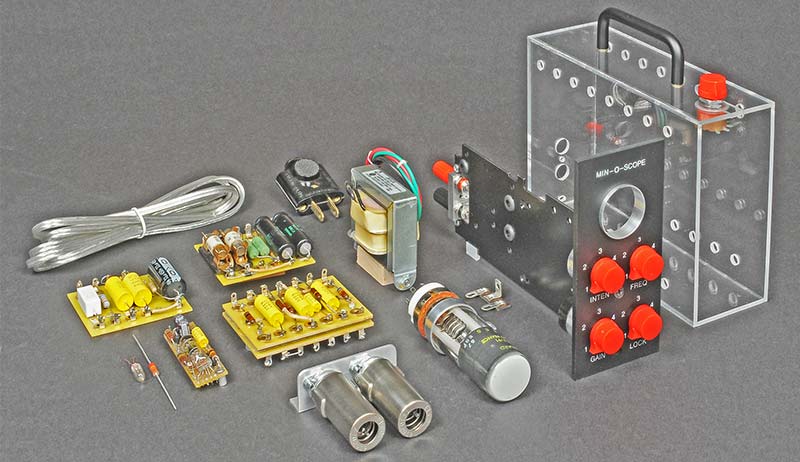
FIGURE 10. I mounted the components on terminal boards and affixed them to a black metal spine connected to the front panel.
Believe it or not, before I mounted everything in the box, I connected all these assemblies together with dozens of clip leads just to make certain that it was ready to be packaged. No problems!
Please also notice in Figure 10 that the black front panel supports a 0.062” thick black aluminum “spine” that extends from the front to the back. Everything was mounted to this spine. Figures 11 and 12 show the final result.
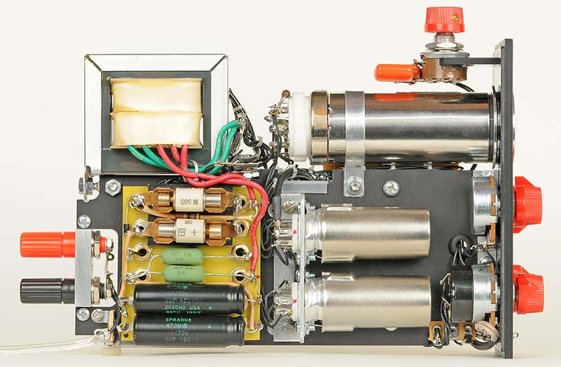
FIGURE 11. The red knobs were found at a shop that services guitar stomp boxes. Go figure! The knob on top is the coarse SWEEP switch.
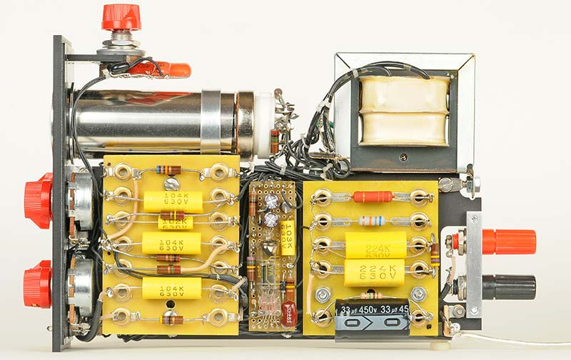
FIGURE 12. The skinny perf board in the middle contains the new retrace blanking circuit with its subminiature Raytheon CK5744 triode.
I was more than pleased with the final layout, although I have to give credit to the original builder for his vision of the Min-O-Scope.
In Figures 11 and 12, you might have noticed the silver tube around the CRT. The original unit included a sleeve of Mu-metal around the CRT to shield it from the magnetic field of the nearby power transformer, T1.
I don’t know if it was necessary or not, but I put it in just to be on the safe side.
ADDING IT TO MY DIAGNOSTIC TOOLBOX
Now that it’s done, it’s sitting on my bench, ready to take on the world. I hope you enjoyed following along on this construction project. It didn’t involve much designing, but I find that sometimes just building things is a challenge and rewarding too. NV
Parts List
| ITEM |
QTY |
DESCRIPTION |
DIGI-KEY (unless noted) |
| C1,C2,C10,C11 |
4 |
Capacitor, 0.1 µF, 630V (104) |
Antique Elec #C-TD1-630V |
| C3 |
1 |
Capacitor, 0.001 µF, 630V (102) |
Antique Elec #C-TD001-630V |
| C4,C9a |
2 |
Capacitor, 0.01 µF, 630V (103) |
Antique Elec #C-TD01-630V |
| C5 |
1 |
Capacitor, 0.022 µF, 630V |
Antique Elec #C-LD022-630 |
| C6 |
1 |
Capacitor, 0.0047 µF, 600V |
Antique Elec #C-PD0047-600 |
| C7 |
1 |
Capacitor, 0.001 µF, 630V |
Antique Elec #C-LD001-630 |
| C8 |
1 |
Capacitor, 220 pF, 500V, mica |
Antique Elec #C-SM220 |
| C9 |
1 |
Capacitor, 33 pF, 500V, mica |
CD15ED330J03 |
| C12,C13 |
2 |
Capacior, 8 µF, 450V |
Antique Elec #C-SA8-450 |
| C14 |
1 |
Capacitor, 33 µF, 450V |
Antique Elec #C-ET33-450 |
| C15,C16 |
2 |
Capacitor, 0.22 µF, 630V (224) |
Antique Elec #C-TD22-630V |
| C17,C18 |
2 |
Capacitor, 220 µF, 25V |
RadioShack |
| R1 |
1 |
Potentiometer, 1 meg, w/SW1 |
eBay |
| R2,R11,R14,R25 |
4 |
Resistor, 47 ohms, 1/2W |
Antique Elec #R-I47 |
| R3 |
1 |
Resistor, 200, 1/2W |
CFR-50JB-52-200R |
| R4 |
1 |
Resistor, 33K, 3W |
PPC33KW-3JCT-ND |
| R5 |
1 |
Resistor, 68K,1W |
FMP100JR--52-68K |
| R6,R23 |
2 |
Resistor, 2.2 megs, 1/2 W |
Antique Elec #R-J2D2M |
| R7 |
1 |
Potentiometer, 1 meg |
Antique Elec #R-VA1ML |
| R8,R15 |
2 |
Resistor, 220K, 1/2W |
Antique Elec #R-I220K |
| R9 |
1 |
Resistor, 47K, 1/2W |
Antique Elec #R-I47K |
| R10 |
1 |
Resistor, 27K, 1/2W |
Antique Elec #R-I27K |
| R12 |
1 |
Potentiometer, 50K |
Antique Elec #R-VA50KL |
| R13 |
1 |
Resistor, 47K, 1W |
FMP100JR-52-47K |
| R16,R21,R24 |
3 |
Resistor, 100K, 1/2W |
Antique Elec #R-I100K |
| R17 |
1 |
Potentiometer, 500K |
2368-502-0418 |
| R18 |
1 |
Resistor, 68K, 1/2W |
Antique Elec #R-I68K |
| R19,R29,R30 |
3 |
Resistor, 1 meg, 1/2W |
Antique Elec #R-J1M |
| R20 |
1 |
Resistor, 680K,750K, 1/2W |
Antique Elec #R-I680K or 750K |
| R22 |
1 |
Resistor, 330K, 1/2W |
Antique Elec #R-I330K |
| R26,R27 |
2 |
Resistor, 4700, 5W |
PPC5W4.7KCT |
| R28 |
1 |
Resistor, 470K, 1/2W |
Antique Elec #R-I470K |
| R31 |
1 |
Resistor, 15 ohms, 1/2W |
Antique Elec #R-I15 |
| T1 |
1 |
Transfmr, 250V, 45 mA, 6.3V, 1A |
Antique Elec #P-T261C6, $34 |
| D1 |
1 |
Diode, 1N4818 |
1N4818RS-ND |
| D2 |
1 |
Diode, 1N4007 |
1N4007RLG |
| D3,D4 |
2 |
Diode, D500 (1N1084) |
eBay |
| D5,D6 |
2 |
Diode, 1N5818, Schottky |
1N5818G |
| V1,V2 |
2 |
Vacuum Tube, 6AU6, Pentode |
Antique Elec #T-6AU6A_EF94 |
| V3 |
1 |
Vacuum Tube, CK5744, Triode |
eBay, Submin, Raytheon |
| V4 |
1 |
CRT, 1 inch, Mullard DH3-91 |
eBay, England, $39 |
| SO1,SO2 |
2 |
Socket, 7-pin Miniature, w/Shiel |
Antique Elec #P-ST7-816 |
| SO3 |
1 |
Socket, 8-pin, Loctal (locking) |
eBay, China |
| SHIELD |
1 |
Mu-metal EMI Shield, 0.004” |
Nooelec.com |
| SW2 |
1 |
Rotary Switch, 1P4T, Grayhill |
eBay |
| KNOB |
5 |
Knob, Small, Red,1/4” shaft |
eBay, Davies #1400 |
| J1,J2 |
2 |
Binding Post Jack, Red, Black |
eBay |
| TERM BRD |
2 |
Terminal Board (Tagboard) |
Antique Elec #P-HTAG-56 |
| PL1 |
1 |
Pilot Light, NE-2 |
eBay |
| P1 |
1 |
Line Plug with Internal Fuses |
eBay |
| F1,F2 |
2 |
Fuse, 1/4 amp, 3AG |
3AG 250-R |
| FRONT PANEL |
1 |
Black Acrylic, 3/16” thick |
McMaster 8505K747 |
| CASE |
1 |
Clear Acrylic, 7” x 5.125” x 2.375” |
shopPOPdisplays.com, custom, $77 |
| HANDLE |
1 |
Black Handle, 3” centers |
Home Depot |