For our Designing With Microcontrollers class at Cornell University, we were tasked with incorporating a PIC32 microcontroller into any project that we could think of. Armed with only a $125 budget, we wanted a project that would be complex, fun to work on, and entertaining for any user. What we eventually came up with was a spin on the classic mechanical pinball machine, which we thought would be a cool way to integrate the PIC32 microcontroller into a highly interactive physical product.
The major aspects of our project (from start to finish) include the mechanical build of the machine itself and the electrical integration of lights, sounds, and sensors with the PIC32. The integration of all these components gave way to an unforeseen challenge of electrical interference, which proved to be very difficult to solve.
Hardware Design
When we first started, we quickly learned that there were a staggering number of design decisions that we had to discuss to make our pinball machine playable. Although many of the components like the flippers and launching mechanism are purely mechanical, we wanted to integrate as many electrical components as we could. It turned out that designing the physical components to be mechanically sound while leaving room for wiring and other electrical components would prove to be the most time-consuming part of the project — especially when we also had to consider aesthetics.
The first aspect of the pinball machine that we considered were the flippers since they’re literally the driving force for a game of pinball. We chose 12V 8A solenoids as the actuation mechanism for the paddles since they would give enough power to launch the ball across the playing field. We had first tested with 2A solenoids. However, the impulse was only strong enough to launch the ball a few inches up the incline of our playing field.
The stronger solenoids, on the other hand, gave the powerful old-school pinball paddle feel that we were looking for. We then used CAD (AutoDesk Inventor) to design and visualize the physical parts we’d need for the game, including the paddles and obstacles on the playing field, which we felt would be easiest to prototype through 3D printing.
After several failed iterations, we ended up with a two-piece design for the paddles: the ball flippers and a lower actuation piece (Figure 1).
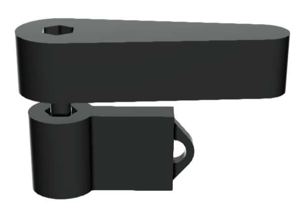
FIGURE 1. CAD of paddle.
A long screw would go through both pieces so that they sandwich the plywood playing field and move as a single unit. We used lock nuts on the screw inside the pieces to secure them in place so the flippers wouldn’t rotate about the screw.
When actuated, the solenoid would strike the lower piece which, in turn, would cause the flipper to rotate (Figure 2).
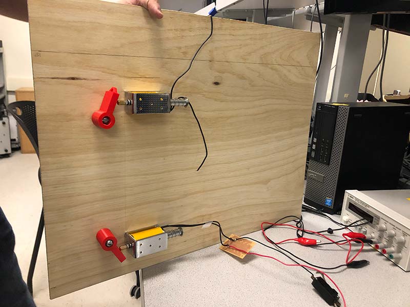
FIGURE 2. Solenoids.
The loop on the lower piece was so we could tie a rubber band to pull back the flippers after being actuated.
In addition to the flippers, we also used CAD to design the obstacles on the playing field: two triangular bumpers and a boomerang-shaped bumper. Since points in pinball are accrued through contacting obstacles, we thought placing limit switches inside of the bumpers would work well for detecting impacts against the raised obstacles on the playing field. Each time the ball hit a bumper and pressed on a limit switch, it would trigger a GPIO interrupt on the PIC, and increment the score by 50. Rubber bands were used to both protect the switches and also to provide a bounce-back effect typical of pinball obstacles.
Again, drawing inspiration from classic pinball machines, we decided to add two tracks on the left side of the playing field. These would be relatively harder to reach than simply hitting the bumper obstacles, so the amount of points for going down these tracks was worth double the points for bumper obstacles.
To detect when balls rolled down the tracks, we used two pieces of copper tape placed extremely close together such that when the metal ball rolls down the track and over the tapes, a connection is made between the pieces, triggering an interrupt and incrementing the score by 100. The triggering was consistent and was a fantastic addition to the game, but the mechanism itself would prove to be slightly problematic; this will be discussed in the “Solenoid EMI” section.
The last design element was the ball launching mechanism. Originally, we thought we would just drop the ball in from the top for simplicity, but we later decided we wanted to stay as true as we could to classic pinball mechanics.
We designed the launcher by placing a wooden dowel through a spring with a square piece on one end. The other end is threaded through a wooden block attached to the playing field. Players could pull back on the dowel, and when the spring tension was released, it would launch the ball rapidly into the playing field.
To accompany this, we decided to add a rounded top for the playing field, since the ball could smoothly ride along the curve after being launched. We used a long Teflon piece supported by wooden pegs behind it to model the curve; the low-friction Teflon surface worked exactly as we wanted for giving the ball a smooth transition onto the playing field. The overall mechanical build is shown in Figure 3.
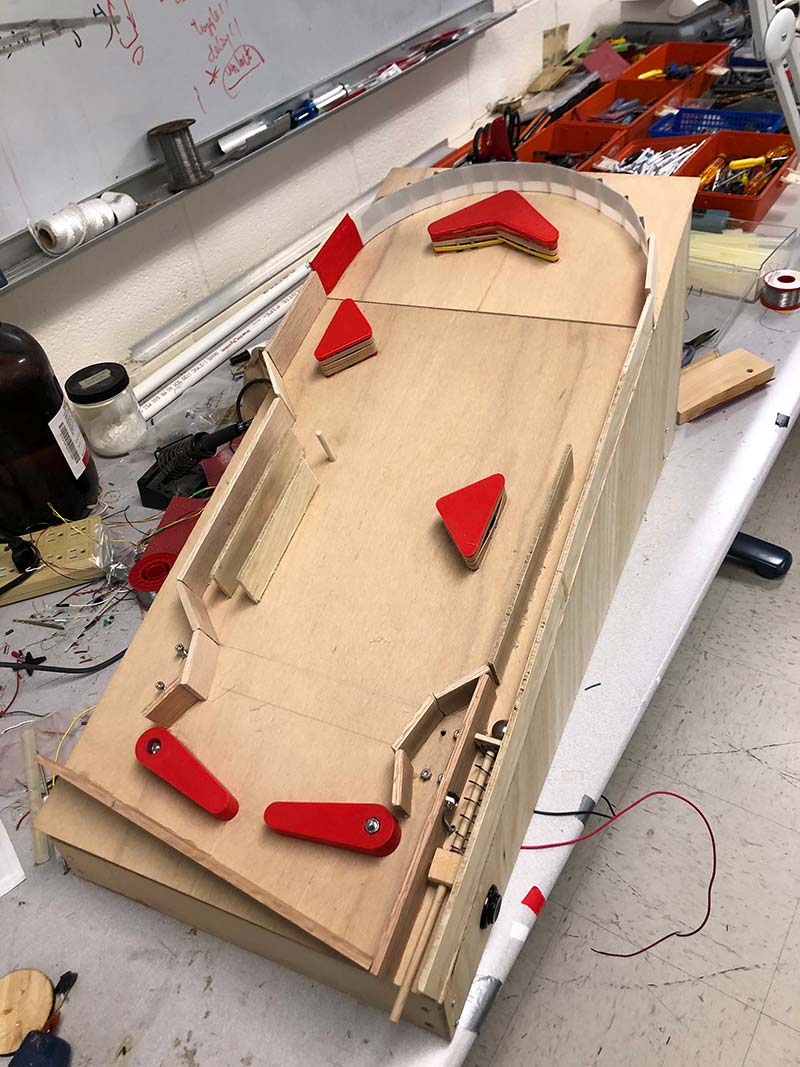
FIGURE 3. Mechanical build.
We displayed the score on a small four-digit seven-segment display, which we placed at the top left of the machine. To drive the display, we used a BCD-to-seven-segment latch decoder (described in the “Program Design” section). We also used speakers to play sounds whenever an obstacle was hit or the ball ran over the tracks.
We modelled the sounds after classic pinball like the cashing of a cash register and the tune of a slide whistle. A start lever was placed on the top right of the machine and an LED strip was added to change color according to the state of the game and the current score.
To power the project, we used a 12V 8A power supply for the solenoids. We used an adjustable DC power supply for the LED strip, which was a 12V strip that drew up to 0.5 amps. We powered the PIC32 itself using a 9V battery. We originally used a 5V power supply, but switched to the battery in an attempt to reduce the effects of electromagnetic interference from the solenoid circuit (more detail is in the “Electrical System” and “Solenoid EMF” sections).
PIC32 Development Board
To give some context to the microcontroller we used for the class, we’ll briefly outline the key components of the PIC32 development board (refer to the system schematic) in this section.
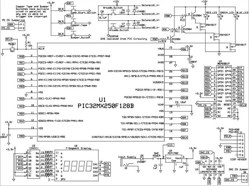
Full system schematic.
The digital-to-analog converter (DAC) on the development board was used to convert the digital signals from the sound files we used to analog audio signals that were played over a speaker. The DAC has two channels: channel A and channel B. We configured channel A such that it would play the “ka-ching” sound and channel B such that it would play the slide whistle sound. Another key component on the PIC32 development board was the I/O expander, which gives us an additional seven GPIO pins using SPI to communicate between the PIC32 and the expander.
This expander was necessary, as we needed 14 GPIO pins total on the PIC32 to drive the LEDs, input interrupts, and seven-segment display. Note on the system schematic that the pins on the I/O expander were exclusively used for the seven-segment display.
Since the PIC32 had to handle driving multiple outputs for lights and sound as well as getting input from the interrupts, we wanted the multitasking for all these different events to seem like they were occurring simultaneously. To achieve this, we used Protothreads — a lightweight threading library by Adam Dunkels — when programming to make it seem like different processes were occurring at the same time. Using interrupts also helped with this since they allow the microcontroller to detect external events instantly (in this case, the limit switch presses).
The Electrical System
For the rest of our electrical design, there are four important circuitry systems to note: the seven-segment display; the switches triggering interrupts; the LED strip; and the solenoids. Each of these systems is also detailed in the schematic. An image of the display is shown in Figure 4.
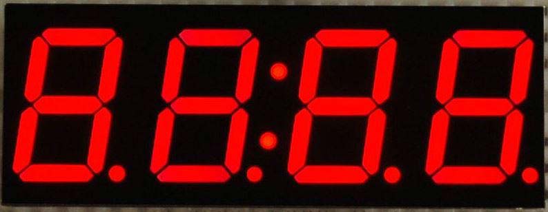
FIGURE 4. Seven-segment display.
For the seven-segment display, we used the Adafruit seven-segment clock display with a BCD-to-seven-segment CMOS decoder for the scoreboard. The purpose of the decoder was to allow a BCD (Binary Coded Decimal) value to be decoded into the proper seven-segment output. For example, we could feed in0011 from four I/O expander pins into the DA, DB, DC, and DD ports on the decoder, and the decoder would turn on the proper segments in the display to show a “3.”
Four other I/O expander pins are used to drive the digit-selector pins CA1, CA2, CA3, and CA4 on the display itself. If a pin is driven high, the corresponding digit is turned on. By rapidly cycling through each digit and different BCD values, we can display four different numbers on each of the digits on the display, which was necessary for scorekeeping.
All the switches that triggered interrupts were connected to one of three input ports on the PIC. The “Game Start” switch was connected to INT0 on port B7 and triggering it would reset the score and toggle between the “idle” and “game start” modes. We used two different segments of copper tape, but since they incremented the score by the same amount (100 points), we connected them to the same input A1 for INT3.
Thus, if the ball rolled down either track, the interrupt would be triggered, incrementing the score while also playing the slide whistle sound. Since all three bumpers also incremented the score by the same amount and we wanted them to play the same “ka-ching!” sound, we tied all the bumper switches to the same interrupt: INT4 on pin B3.
For the LED strip, we used a non-individually addressable 12V alternating RGB LED strip. We were planning to use a fancier strip that would be able to light up specific parts of the playing field based on which interrupts were triggered, but due to budget concerns we stuck with a much more inexpensive strip.
We used PWM output pins on the PIC32 connected to 2SK4017 power MOSFETs to drive the three different colors (red, green, and blue) for on, off, or some value in between. We originally tried hooking up the PIC PWM output pins directly to the FETs, but we found that the output voltage was lower than the switch turn-on voltage, as the datasheet ID vs. VGS curve suggests using more than a five volt drive.
To solve this, we added intermediate 2N3904 NPN transistors which would be turned on/off by the PIC PWM output and could give the required input voltage for the 2SK4017s (refer to the schematic). This gave us full control of each color output on the LED strip, allowing us to program several cool patterns.
Lastly, for the solenoids, at first we just had the suppression diode across the positive and negative terminals to help prevent the sudden voltage spike typically seen across inductive loads (in this case, the 100W solenoid is a massive inductive load) when the supply current rapidly changes when the paddles are triggered/released. However, when we ran into the issue of significant electromagnetic interference from the solenoid, we added capacitors across both the solenoids and also between 12V and GND in an attempt to add decoupling to the system to reduce noise.
This was somewhat successful, but there were several other solutions we had to implement to reduce this issue to a reasonable degree; these are detailed in the “Solenoid EMF” section.
Programming
The first design decision when writing the software was determining whether to poll or use interrupts to determine when the ball interacted with any of the playing field obstacles. At first, we tested with polling which we found to be consistent enough because we had enough CPU time to spare. However, once we tried to implement the seven-segment display, we found that we needed as much CPU time as possible to continuously update the seven-segment display, and that interfered with the polling method.
Therefore, we decided to use three external interrupts to deal with updating the score and game start/reset so that the PIC would be automatically alerted when the ball hit something in order to update the score.
The next part of the project that we had to implement programmatically was the seven-segment display. To control the seven-segment display, we would display one of the four digits at a time, but cycle through all the digits rapidly enough so that it would seem like all four digits were on at the same time.
We achieved this within our scoreboard thread which handled cycling through each digit as quickly as possible, while also making sure that the output pins for displaying the number were correct.
One concern we had about our seven-segment display was playing sound and how much CPU time that would steal from the scoreboard thread since both are CPU-intensive, but we needed the scoreboard to update quickly enough that it didn’t look like it was flickering.
We used the method of direct digital synthesis to produce sound through the DAC on the PIC32 board. Since we relied on interrupts to handle the sound transmission, we had two main concerns when dealing with sound and the scoreboard thread: moderating SPI between the DAC and the port expander (since only one could be active at a time); and determining the least amount of timer interrupts we could have while still having reasonable sound quality.
We compromised between display updates and interrupt frequency by settling on an 8 kHz rate for the sound output rather than CD quality (44 kHz). That allowed the scoreboard to function properly while still providing clearly audible sound effects. We also customized our sounds by importing audio files and converting them to arrays of digital samples. So, whenever a sound was queued up to be played, we would simply loop through the array of digital samples in the timer interrupt handler — one sample per invocation of the handler — to transmit to the DAC and play the sound.
The final software element that we implemented was the control for the LED strips. To turn on any of the three colors, we simply had to pull a pin connected to the LED strip low (Figure 5).
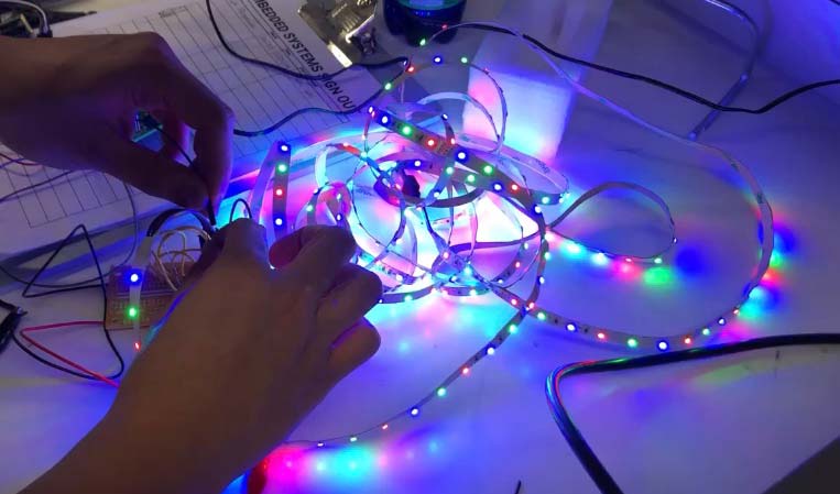
FIGURE 5. The LED strip.
However, such an effect is not desirable because the LEDs would be blindingly bright if they were only fully on or fully off during gameplay.
Therefore, we relied on the output compare functionality of the PIC to use PWM to control the brightness of the LEDs. The output compare pins relied on Timer 2 — the same timer that we used for our direct digital synthesis — so we were running the PWM at a frequency of 8 kHz.
Our LED strip had two states throughout the operation of the game: a glow effect before the start of the game, and another mode where each of the three LEDs would lowly start turning brighter based on the score. In the pre-game state, we relied on a triangle wave signal that would slowly increment and decrement the PWM duty cycle.
Once the game started, we switched to a different mode that relied on a piecewise linear function to slowly decrement the PWM duty cycle of each LED. The first LED would turn on to full brightness at 2,500 game points; the next LED turns on to full brightness between 2,500 and 5,000 points; and the last LED turns on to full brightness between 5,000 and 7,500 points.
Solenoid EMI: Our Greatest Challenge
When we interfaced the PIC32 board with the rest of the machine and connected the solenoids up for our first test, we were pleasantly surprised that the systems appeared to be functional after being integrated. The LED strip was on, the scoreboard was displaying properly, and when we touched the switches the score would increment as intended. However, a problem arose which we noticed as soon as we triggered the flipper solenoids after integrating everything else.
The most noticeable effect was that the various interrupts would trigger automatically and increment the score. Even more bizarrely, we found that we had the same issue whenever we plugged in any device into the same extension strip that was powering the PIC.
To combat this issue, we isolated the power for the PIC by powering the microcontroller with a 9V battery (through an LDO regulator) which would isolate it from the strip that was powering the external power supplies. However, this only slightly reduced some of the interference issues we were having.
Pretty quickly, we realized that the high current being drawn through the solenoids was causing electromagnetic interference (EMI), which induced current on nearby wires and thus triggered interrupts for obstacles whenever the paddles were actuated. The first thing we tried to solve this issue was to move from using internal pull-ups on our external interrupt pins and convert to external pull-ups. The reasoning behind this change was that the internal pull-ups on the pin are on the order of magnitude of a 100K ohms, and as a result there is very little difference in the current through the pin when the input is triggered as opposed to not triggered.
An external 5K ohm pull-up resistor draws significantly more current when the input is triggered, so the current induced by the EMI from the solenoids would be less likely to trigger the interrupt. While this method worked to cut down some of the interference, there was still an unacceptable amount affecting game play.
Our next approach was placing 0.01 µF capacitors across the solenoids to act as a low pass filter and suppress some of the high frequency noise from the solenoid from interfering with the PIC. Unfortunately, this was still not enough to solve our problem.
Our last attempt implemented through hardware was to create a Faraday cage around any of the wires that were connected to the obstacles in hopes that the cage would shield the wires from any excess charge. After finding a roll of foil in the lab, we began to wrap these wires from the base of the board all the way to the PIC itself.
For each pair of wires (ground and pin), we grounded the foil to the board and moved the wrapped wire as far away from the solenoids as possible. While this solution worked surprisingly well for the bumpers, the interrupt would still get triggered every so often because the copper tape is an exposed conductor and covering them up would not be possible. Thus, we resorted to using software to debounce some of the interrupts as well.
Our approach with debouncing the software was based on our assumption that the EMI from the paddles is very brief, but just long enough to trigger the interrupt once. Placing the interrupt input on the oscilloscope demonstrated that our hunch was correct. For a very brief moment in time, the signal would be pulled low when the paddle was actuated.
So, with this in mind, we designed an interrupt debouncing routine where two successive interrupts would have to be encountered within 50 ms to register as a valid interrupt input. The idea is that the impulse was fast enough to trigger one interrupt. So, to try to filter out misfires, two successive interrupts would have to be generated, which would more likely correspond to a legitimate scoring mechanism triggering.
We designed a simple FSM (Figure 6) in which the state after “waiting” corresponds to the first interrupt handler call, and the third state corresponds to the second interrupt handler.
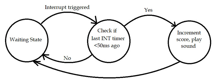
FIGURE 6. Interrupt FSM.
The transition from the second state to the third state only happens if the interrupt is triggered again within 50 ms.
Once the FSM reaches the third state, we go through the additional debouncing routine from before the score is updated. We reached this value of 50 ms by manual tuning of the system and seeing what value would capture almost all the proper interrupt triggers while eliminating as many misfires as possible.
This debouncing routine worked really well for the most part and eliminated almost all of the noise. Sometimes, there are accidental triggers which increment the score. We’ve noticed that this could be linked to coupling effects from the ball travelling through the playing field. We have deduced from experiments where the ball is not in play and when the ball is in play that the EMI gets significantly worse when the ball is in play.
Our assumption is that the conductive nature of the ball makes the interference that much more potent. In addition, the proximity of the wiring between the PIC and the solenoid circuits directly correlates to the potentness of the EMI. So, we ended up having to strategically place some of our inputs away from the PIC.
Results and Conclusions
At the end, we were able to give a playable demonstration of our PICBall Machine, and we were very satisfied with the result (Figure 7; see the demonstration video link in Resources).
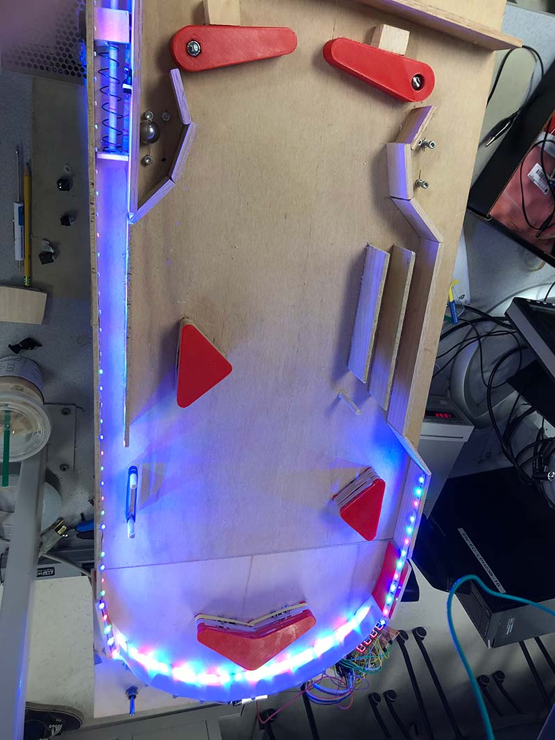
FIGURE 7. Finished playing field.
However, that’s not to say that our current product is perfect. If given more time, there are several things we would have liked to address.
Though we were able to reduce the effects from the EMI, it was only to a degree where it would not significantly detract from gameplay; accidental interrupt triggers would occur much less frequently, making it difficult to obtain a definitive percentage of accidental triggers. This was the most obvious gameplay flaw in our design; one that we didn’t anticipate and thus was a problem that we only encountered very late in the design process.
In hindsight, we should have tried putting the overall system together earlier, which likely would have let us discover this issue sooner, and thus have more time to brainstorm and attempt more effective solutions.
Aside from this issue, all our other systems worked just as we expected. The LED strip greatly enhanced the aesthetics of the pinball machine, which was our main purpose for including them in the first place. The limit switches and copper tape sensors worked rather consistently, and the incrementing score and sounds made the gameplay much more exciting and meaningful.
The solenoids — while problematic for the software side — were very satisfying to actuate using the arcade buttons that we obtained, and were powerful enough to launch the ball all the way to the top.
Other design aspects that we would improve on are the paddles and the aesthetics. The current method we use to secure the flipper and actuation piece onto the screw is still not robust, and after several minutes of gameplay the pieces have to be readjusted. Additional elements like a Plexiglas cover on the playing field and individually addressable LEDs would further enhance the aesthetics of the machine.
Although we have a list of additions and modifications we would like to make, we are still very satisfied with the results of this project — especially considering our time and budget limitations.
We achieved the functionality and aesthetics that we had envisioned at the start of the project, and seeing it come together and seeing other people having fun playing it made us consider our PICBall Machine to be a success overall. NV
Parts List
| Small Board |
| Description |
Value |
Part Number |
Vendor |
Qty |
| C1, C2 |
100 nF |
399-1249-1-ND |
Digi-Key |
2 |
| C3 |
10 µF |
311-1376-1-ND |
Digi-Key |
1 |
| C4, C5 |
1 µF |
311-1181-1-ND |
Digi-Key |
2 |
| D1 |
1N4007 |
641-1614-1-ND |
Digi-Key |
1 |
| J1 |
ICSP Header |
(M-M Headers) |
Digi-Key |
- |
| J2 |
Input Supply |
(2.1 mm Power Jack) |
- |
1 |
| J3 |
Power/DAC Outputs |
(M-M Headers) |
- |
- |
| J4, J5 |
PIC GPIO |
(M-M Headers) |
- |
- |
| R1 |
10K |
RMCF1206JT10K0CT-ND |
Digi-Key |
1 |
| SW1 |
Reset |
(Pushbutton Switch) |
- |
1 |
| SW2 |
Power |
(Toggle Switch) |
- |
1 |
| U1 |
PIC32MX250F128B |
PIC32MX250F128B |
Microchip |
1 |
| U2 |
MCP1702 |
MCP1702-3302E/TO-ND |
Digi-Key |
1 |
| Note: SPDIP (0.3”) sockets are recommended for any chips/displays (UX), In the case of the TFT, a female-to-male header will do. |
| Large Board |
| Description |
Value |
Part Number |
Vendor |
Qty |
| C1, C2 |
100 nF |
399-1249-1-ND |
Digi-Key |
2 |
| C3 |
10 µF |
311-1376-1-ND |
Digi-Key |
1 |
| C4, C5 |
1 µF |
311-1181-1-ND |
Digi-Key |
2 |
| D1 |
LED |
(Red LED) |
- |
1 |
| D2 |
1N4007 |
641-1614-1-ND |
Digi-Key |
1 |
| J1 |
ICSP Header |
(M-M Headers) |
- |
- |
| J2 |
Input Supply |
(2.1 mm Power Jack) |
- |
1 |
| J3 |
Power/DAC Outputs |
(M-M Headers) |
- |
- |
| J4, J5 |
PIC GPIO 1 |
(M-M Headers) |
- |
- |
| J6, J7 |
Port Expander PortY |
(M-M Headers) |
- |
- |
| J8 |
DAC CS Jumper |
(M-M Headers + Jumper) |
- |
- |
| J9 |
TFT CS Jumper |
(M-M Headers + Jumper) |
- |
- |
| J10 |
PE CS Jumper |
(M-M Headers + Jumper) |
- |
- |
| R1 |
10K |
RMCF1206JT10K0CT-ND |
Digi-Key |
1 |
| R2 |
330 ohm |
P330ECT-ND |
Digi-Key |
1 |
| SW1 |
Reset |
(Pushbutton Switch) |
- |
1 |
| SW2 |
Power |
(Toggle Switch) |
- |
1 |
| U1 |
PIC32MX250F128B |
PIC32MX250F128B |
Microchip |
1 |
| U2 |
MCP1702 |
MCP1702-3302E/TO-ND |
Digi-Key |
1 |
| U3 |
MCP4822 |
MCP4822-E/P-ND |
Digi-Key |
1 |
| U4 |
MCP23S17 |
MCP23S17-E/SP-ND |
Digi-Key |
1 |
| U5 |
TFT Display |
(TFT Display) |
Adafruit |
1 |
Downloads
What’s in the zip?
Code
Schematic
PCB Files
PICKit3 User’s Guide
Assembling the Large Board Instructions
Port Expander Example