Ken Gracey, CEO of Parallax, Inc., and I aren’t exactly email pen-pals, but I recognized the sender and opened the email with heightened interest. Ken wrote to tell me that he was offering $50 off the price of Parallax’s Propeller 2 Evaluation Boards. I’ve used the Propeller 1 for a number of small around-the-shop projects and have paid casual attention to the development of the Propeller 2, so I was excited at the price reduction and immediately placed an order.
In nearly no time at all, I got my new P2 EVAL board (Figure 1).
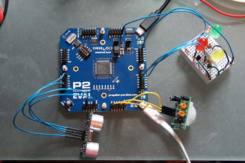
Figure 1 - The P2 EVAL board, sensors, and status LEDs. The "ACC HDR 5V" jumper (see text) is in the upper right by the black USB cable.
Wondering just what I should do with my new treasure, the idea of “social distancing” came to mind, given the recent COVID-19 pandemic.
So, I developed a project that uses a motion detector and distance detector to tell — via some status LEDs — whether a moving object is too close (red), getting too close (yellow), or is a safe distance away (green).
Important Note: This project does nothing to help stop the spread of COVID-19. It’s for entertainment and educational purposes only.
But first, a fly in the ointment …
Of course, the first thing we do with new boards is a “blinky light” program to make sure that the hardware is minimally functional and that our development tools work with the new board. Lots of Propeller developers are completely happy with Spin or PASM, but I’m a long-time C programmer and cracked open SimpleIDE to fire off a quick and dirty blinker.
I quickly discovered that was the wrong answer! SimpleIDE only works with Propeller 1 chips. The developer of SimpleIDE has not produced a Propeller 2 compatible version and there have been no rumblings or rumors that he might. This is unfortunate, since SimpleIDE made C development for the Propeller, well, simple.
Scouring the forums at Parallax, I found that there were four tools for C development. I settled on FlexGui, which has a version for the Mac — my preferred development host. FlexGui is a perfectly competent development environment, but once I got it set up, I found I worked faster with old-fashioned VIM for text editing and the command line to compile and run the binary on the target board.
Using command completion, I can quickly arrow-up to a previous compile-and-execute command, change parameters if necessary, and then fire off another round of testing. Fewer mouse movements make for faster workflows (Figure 2).
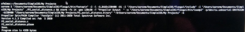
Figure 2 - Command line on a Mac to compile and execute the Propeller code using the FlexGui compiler and program loader.
Once I got a working compiler and board programmer, I could begin in earnest on my actual task: keeping people the heck back.
Hardware Design Overview
The design goal is relatively simple: When a motion detector senses motion, use a distance detector to measure how far away the object is. Sure, I could probably use the distance detector continuously, but I wanted to use the motion sensor to help put the Propeller 2 through its paces. Plus, if there isn’t any motion for so many seconds, all the LEDs are turned off, saving a small amount of power.
Based on the distance, we light up one of three LEDs (green, yellow, red) to indicate whether the object’s distance is “safe” (green), “getting unsafe” (yellow), or “dangerously close” (red). The distances I used are arbitrary and can be easily changed within the code.
Given all this, our hardware bill of materials is relatively short:
- The Propeller 2
- A PIR (passive infrared) motion sensor
- An ultrasonic distance sensor
- Some LEDs
- Some transistors to drive the LEDs
- Some passive components to tie it all together
Why the Propeller 2? As I’ll touch on more fully below, the Propeller platform has some very useful features for embedded development. I have quite a few Propeller 1s in my stash of development boards. Ken Gracey and his team at Parallax have been working on this next iteration of the Propeller for over 14 years.
This will not be an in-depth review of the Propeller architecture, and you can find way more information on the official Parallax website (see Resources), but at the heart of the Propeller is the concept of “cogs.”
In simple terms, a cog is essentially a separate processing core. Think of multiple, separate, but still connected, microcontrollers in one device. Propeller 1s have eight cogs, which means a developer can control eight separate programs simultaneously on one microcontroller.
Cogs can also share resources between them; we’ll see an example when we discuss the code. The Propeller 2 will reportedly have up to 16 cores, but the P2 EVAL is still an early fabrication release, so only has eight cores. It’s still faster and has more memory than a Propeller 1, and has tons of exposed I/O pins. So, there’s a benefit to upgrading, if you don’t absolutely need 16 cores right now.
Logic Design
As mentioned, one of the benefits of using a Propeller 1 or 2 is the availability of cogs. Using a cog, I can fire off a small self-contained program to, say, monitor an I/O pin or manage a timer. In fact, in this application, I use cogs to do both these things.
This design uses three cogs:
- One for the main program that starts the other cogs and manages the distance and LED control.
- One to monitor the PIR sensor for motion.
- One to run a timer to stop checking for distance when we no longer detect motion.
Using cogs, I don’t have to set up or manage interrupts as with other microcontrollers. The self-contained programs running in cogs simplify program development.
SimpleIDE provided a mature library of C code to interface with many kinds of sensors. However, since the Propeller 2 is relatively new and not 100% backwards-compatible with the Propeller 1, the library code base isn’t yet “soup,” so I had to tinker and write some driver-type code myself, which was actually kind of fun.
For example, the ultrasonic distance sensor module I have is an older unit; something I had available in my parts bin. Instead of a single pin to perform the trigger and echo functions, it has separate trigger and echo pins.
To initiate a distance measurement, you:
- Pulse the trigger pin for 10 µs.
- Wait for the echo pin to go high.
- Read the echo pin until it goes low again.
See the Resources for an excellent technical description of how ultrasonic sensors work. The length of time that the echo pin was high gives you an indication of how far away the object is. The longer the high pulse, the further the distance. There is some simple math to get the actual distance, but that’s the gist of it.
For testing, I wrote code to pulse the trigger pin for 10 µs, and then used my oscilloscope to verify that the pulse was the correct width (Figure 3).
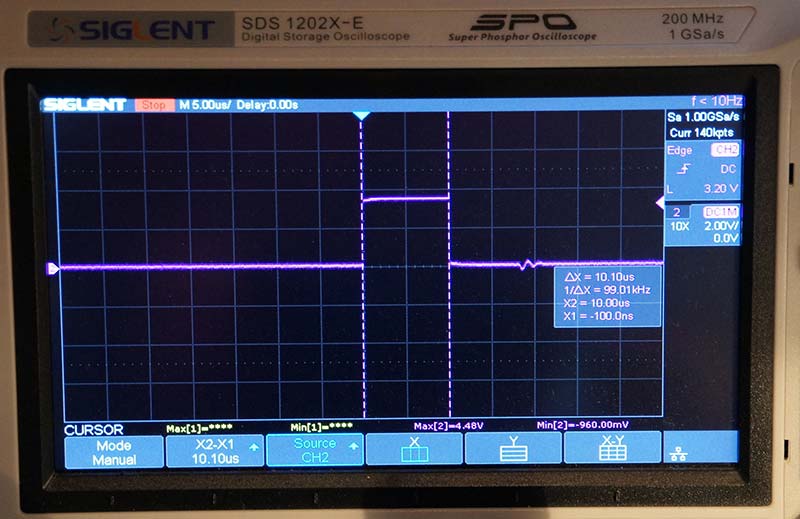
Figure 3 - Oscilloscope output from pulsing the ultrasonic trigger pin for 10 µs. Physical output shows a close correlation to the program code.
Here’s a simplified description of the software logic:
- Initialize the I/O pins.
- Start the support cogs.
- Loop forever:
- If the motion timer has expired, turn off all LEDs and sleep for a bit.
- Otherwise, measure the distance of the object in view, and turn on the appropriate LED: green, yellow, or red.
Software in a Cog
Generally speaking, you write cog code to run forever. Of course, there are cases that break this rule, but it’s a good general guideline. So, where the main program in a microcontroller uses a “loop forever” construct, so does a cog.
Within the timer cog, we run forever to count a timer variable down to zero and sleep for a second between each check. Could not be simpler. This little four-line code snippet happily runs in its own space without concern for anything else in the processor.
The passive infrared (PIR) motion detector cog is only slightly more complex. It also runs forever, checking the state of the PIR pin. If the pin is positive, indicating motion, it sets the timer variable to an arbitrary 10 seconds. This is where shared resources come in handy.
The timer cog, PIR cog, and main cog all use the timer variable. The timer cog tries to bring the variable to zero while the PIR cog sets it to 10, as necessary. The main cog merely checks to see if the timer variable is zero, and, if so, turns off all LEDs.
Because of the potential constant changes to the timer variable, we declare the timer variable as volatile. This is a C keyword that tells the compiler that this variable may change at any time during an instruction execution, and not to optimize out any instructions that might refer to it.
If I were developing an application that had life-or-death consequences, I could have used semaphores or other resource-locking mechanisms for variable safety. For this small project, it wasn’t necessary.
Using cogs, I don’t have to set up or handle interrupts. My code to handle those tasks is clean and simple. I believe in the right tool for the right job, and will happily use other microcontrollers if they’re a better fit. However, because of the Propeller’s cogs (which make handling sub-tasks so much simpler), I tend to lean toward Propellers for my projects, unless I can’t.
Building the Project
The P2 EVAL board came with the “ACC HDR 5V” jumper disconnected, so you have to enable that for the various 5V pins to work.
I used simple 2N2222-type transistors to drive the LEDs to avoid problems with current draw from the Propeller 2. Perhaps the P2 EVAL can drive the LEDs straight from the board. I didn’t want to risk it. Using some transistors and resistors, the LEDs draw minimal current from the board.
For the red LED, I used a 1K Ω resistor, since red LEDs typically use less current than other colors. For yellow and green, I used 220 Ω resistors (Figure 4).
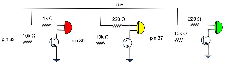
Figure 4 - Schematic for LED drivers. Note the different resistor value for red compared to yellow and green.
Since this was primarily a learning experience with the P2 EVAL rather than a deployed product, I didn’t build an actual project housing for this. That was unfortunate. One thing I’ve come to learn is that projects work much better overall when you implement the hardware components in permanent positions. Then, you can work out the wire routing, not have to worry about components flopping around, falling out of place, etc.
Testing for motion and distances would have been so much easier if I’d had a project box drilled to hold the sensors in place. However, since I fully expected to disconnect everything when I was happy with the performance, I didn’t bother with a case.
Wrapping Up
One thing I noticed with the distance detector is that the detection area gets spotty after about half a meter. Using my hand as the motion source was hit-and-miss due to ultrasonic signal spread.
Using an 8.5”x11” notebook as my motion source, detection was much more consistent. If I needed higher accuracy, I’d probably add multiple ultrasonic sensors aimed in different directions.
Finally, while just about everything with the Propeller 2 is in flux at the moment, I have high hopes that the hardware and software aspects will improve as the platform matures.
If you’re unfamiliar with the Propeller, give it a try. I’m sure it will find a special place in your microcontroller toolbox. NV
Downloads
What’s in the zip?
Source Code