My wife and I are proud parents of a University of Michigan Physics graduate teaching high school mathematics and computer science. I’m especially lucky because my son shares my interest in science and technology. I must admit that when he was a youngster, I didn’t want to leave this purely to chance. I built many electronics projects tailored for pre-teens in an attempt to sway him towards technology and the sciences.
Of all the projects we jointly worked, the Super-Secret Invisible Burglar Alarm is one of my favorites (Figure 1). Aimed at 8–12 year olds, it takes a somewhat ordinary microprocessor based alarm system and adds a sizable element of secrecy that is very appealing to kids in that age range. For hobbyists who are already involved with programming PIC microcontrollers, this project would only take a few hours to build.
FIGURE 1. This is the plywood safe, protected by the Super-Secret Invisible Burglar Alarm. To open the safe’s cover, the user can insert a small piece of stiff wire into a 1/6” hole on the far side, causing an internal latch to release. To avoid the use of hinges, the side of the safe opposite the latch is secured by a pair of small dowel rods or nails inserted into holes in the frame.
Before we dive into the circuit details, a little background is in order. While working on this project, I wanted to expose my son both to the products of engineering and to the overall engineering process, generally simplified as the steps: specify, design, build, and test. Therefore, the first section of the article will also illustrate the requirements development process that either consciously or unconsciously enters into any design project. The logic is from a 10-year-old’s point-of-view, but the process I attempted to teach him is very similar to what I use daily in my engineering profession.
Readers who don’t have an interest in this particular circuit can still hopefully take something more important away from this article: the need to expose the country’s youth to technology. Exposure is a first required step on the road to a career in a technology based trade or profession.
Project Background
One thing parents need to teach their children is to take proper care of valuable items (which, for 10-year-olds tends to be birthday gift money, any coins older than 20 years, and an occasional dried bug found in the backyard). To teach them to protect these treasures, they need to have a safe and consistent spot in which to store them.
Our son’s bed had a bookcase built into the headboard. As a result of this, it has some unused space on the back. My son and I built a small wooden enclosure on the back which became the primary storage location for his prized possessions.
The enclosure was built using the same type of wood as the headboard and it didn’t have any visible hinges or latches — all of which helped keep it from looking like an addition to the bed.
To open the enclosure, a two inch length of stiff wire is inserted into a small inconspicuous hole, which popped an internal latch allowing the cover to be removed. It was very secret, and hence very cool.
It was a secret location, but “what if someone did figure out it was there?” my son reasoned.
“Good point. How else could we keep if safe from a burglar?” I asked in response, subtly starting the requirements development phase that is so critical to the design of any engineering project.
We talked about a lock. This would be very easy to install on the cover, but it would take away from the secrecy since there would be no other reason for an exposed lock. One solution to this might be hiding the lock, possibly from underneath. My goal was to keep him thinking of alternative solutions (plus, I was hoping for more of an electronic based solution), so I noted that locks can sometimes be defeated. He thought some more.
“We need an alarm!” was his next design concept — the super-secret storage location needed a super-secret burglar alarm to go with it. This solution would certainly be electronics based, so we had a winner as far as I was concerned.
With a core design concept selected, it was time to work on the associated design requirements for the alarm. Again, I had to remind myself that it was much more important to me that he learn the engineering design process, rather than simply build a circuit to protect a 1942 Wheat Penny from being stolen. From an engineer’s perspective, I was teaching my son how to fish.
The discussion moved to the required elements of the alarm: a small limit switch on the door to detect the enclosure being opened; a buzzer for an audible signal if it were opened; batteries for power; and finally some method of disabling the alarm when he wanted to get into the safe. Again, we talked about alternatives on how the circuit would work — at least as deeply as you can consider these issues from a 10-year-old’s perspective.
For example, one possibility for the disabling mechanism was a keypad. With a keypad, he could deactivate the circuit using a four-digit code prior to opening the door. An exposed keypad, however, would again eliminate the secret part of the project since there would be no other explanation for a keypad in that location. He liked the security of a secret code, but he didn’t want to jeopardize the hidden aspect of the enclosure.
I’d previously exposed him to the invisible world of magnetism and, in particular, the ubiquitous reed switch. He applied this knowledge to the current project, simultaneously generating an intriguing design solution while also making his father very proud.
The first prototype consisted of a normally-closed reed switch on the inside of the enclosure in series with a battery, a door switch, and a buzzer. When you want to open the enclosure, simply place a magnet on the appropriate spot on the side of the box to open the reed switch to disable the alarm.
It was a simple circuit that worked well. However, in the testing phase, my son realized that anyone who knew where to place the magnet could defeat the system. With this design, there was still significant insecurity in the system.
In this process, my son came to realize a basic truism of engineering: “Your first design is your worst design.” Design, build, and then test your projects. When you find significant flaws in any design, it becomes time for yet another design iteration, where you specifically focus on designing out the flaws of the previous iteration.
“I wish I could have a secret code,” he said.
Bingo! The project just moved from a pure teaching exercise to something with which dad was going to have some fun. Secret codes imply microprocessors, which for me, this meant a PIC. Our new concept was to use the hidden reed switch as an input line to a microprocessor. The PIC would count magnet pulses for each digit of a code number and if the wrong code were entered before opening the safe’s door, the circuit would subsequently sound the alarm.
Originally, we planned to use the somewhat standard four-digit code. After building the second prototype, it was obvious that entering a digit in this fashion took a significant amount of time, so the code length was dropped to only two digits (and preferably low digits at that!).
The Circuit
The required I/O count for the microcontroller was at three pins: two inputs to detect the reed and door switches; and one output to run the small buzzer. I had plenty of PIC12F629 devices in stock, so I ended up having a total of six I/O lines available. Because we had extra, I also added in a small pushbutton switch on the circuit board to allow my son to enter a new secret code any time he wanted. (Generally, he would change the code after demonstrating the safe to a friend. After all, what fun is having a secret if you don’t tell anyone?)
Figure 2 shows the schematic diagram. The buzzer draws only about 10 mA, so it’s low enough current that it can be directly driven from the PIC’s output pin. Both the switch inputs are normally open, but this doesn’t matter a great deal since you could easily change the logic in the microcontroller’s code.
FIGURE 2. The schematic for the alarm circuit, complete with several testing points. Originally, SW2 was for debugging purposes but it became the “learn” button to enable resetting of the alarm’s deactivation code.
Power comes from three AA batteries in series, again maintaining the stealth nature of the design much better than would a wall-wart connecting to the enclosure. Three 1.5V cells only provide about 4.5 volts to power the circuit; the schematic lists 5V for simplicity. Because the PIC12F629 has such a wide operating range, the circuit will work with only two AA batteries, but the alarm volume is greatly reduced.
Another benefit of using the battery pack is that it gave my son the periodic responsibility of checking and changing the batteries in the circuit. (Some parents are likely to find that teaching kids to learn responsibility via batteries is much cheaper than learning it via goldfish.)
Because the limit switch to detect the opening of the main door is connected to the printed circuit board (PCB), the entire PCB was mounted on the wall inside the safe. This allows for activation of the limit switch arm when the door opens. Figure 3 shows the PCB with the components soldered into place.
FIGURE 3. This circuit is simple enough to be wired on perfboard in just an hour or so. This version used a dedicated PCB, shown here with components soldered in place.
The circuit board also includes the reed switch, but this can easily be mounted remotely if it’s not in a convenient location for swiping the magnet. We kept the reed switch on the PCB since the magnet we used was more than powerful enough to work through the 3/8 inch thick plywood of the wall of the safe. (Side note: This is possibly the first time in the history of print that the word plywood has been used to describe the construction of a safe.)
Figures 4 and 5 show the top and bottom layers of the PCB, respectively.
FIGURE 4. This is the top layer of the PCB.
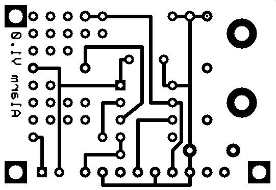
FIGURE 5. This is the bottom layer of the PCB.
Software & Operation
I actually enjoy coding in assembly language. However, I didn’t want to dampen my son’s enthusiasm for the project with a lengthy coding process, so I used a unique BASIC complier. The complier outputs an assembly language version of the code as well as the hex version that can be used to directly program a PIC. The files required to directly program your own PIC microcontroller can be found in the article downloads.
Assuming you’ve programmed your PIC with the default code, powering up the circuit will cause it to simply sit there. The user needs to enter a code via SW2 (also labeled DEBUG on the schematic). For example, if you want 21 to be the safe’s combination, here’s the sequence:
- Press SW2 two times and wait. For each press, U1 will do a short beep of the buzzer to let you know it received the input.
- Wait until the piezo electric buzzer quickly beeps twice, indicating it’s ready to accept the second digit of the code.
- Press the SW2 switch one more time, inputting the second digit of the safe’s combination.
- When U1 goes two seconds without getting any more inputs, it will write the two-digit code to EPROM memory. In this way, the code will be retained even if batteries to the circuit are removed.
With the safe’s combination now programmed into U1, you can begin using the system.
Once the safe door is closed, this will cause the closure of switch SW3. The circuit automatically arms itself and is ready to go. Opening SW3 at this point will sound the alarm.
The user needs to enter the disable code via the reed switch prior to opening the safe’s door. During testing, we found that the circuit would occasionally miss swipes of the magnet, most likely due to misalignment of the magnet over the reed switch. It was another educational moment on the benefits of testing engineered systems prior to releasing them for general usage. Version 2.0 of the software emits a short beep whenever it detects the reed switch being closed by each swipe of the magnet.
At this point, the code is basically in a loop watching for closures of the reed switch, following the exact same process that was used to enter the combination via SW2.
Each time SW1 is momentarily closed via a magnet swipe, the micro simultaneously increments the first digit counter and starts a timer. If the micro sees another swipe, it will again increment the digit counter and reset the timer.
During this phase, if the PIC goes about two seconds without seeing a swipe it assumes the user is done entering the first digit and it will move on to the second digit of the two-digit code. At this transition point, the software will generate another beep to let the user know digit one is complete and it’s ready to receive digit two.
The same software algorithm is used to enter the second digit of the safe’s code number. Once it stops seeing reed closures for the two second period, it assumes the code has been completely entered. It compares the two digits entered with the two digits it has stored in its Flash memory. If they match, it will disable the alarm and give three quick beeps to let you know the code had been entered correctly. You are now able to open the safe’s door.
Possible Extensions
The original purpose of the project was to expose my son to an early engineering education, but I must say I probably learned more on this project than he did. We never did another design iteration of the alarm, but if we had, I know of a few design changes that would be incorporated.
Future revisions would certainly include some form of a battery check circuit where the PIC would occasionally read the battery voltage and generate a unique beeping pattern only if the batteries needed to be changed.
Analog-to-digital conversion is fairly simple on the PICs, and this small design extension would have prevented more than a few perfectly healthy batteries from giving their lives for the advancement of science education.
One aspect of the project that was more difficult than I had expected was the timing of the secret code entering sequence. As we were learning to enter the digits, it took some practice to make the swipe slow enough that the reed switch could close.
During tests with early versions of the software, if we missed a swipe because of a misaligned magnet, the code would not wait for you to have a second try. It prematurely moved on to the second digit. Because there is no cancel button, you have to wait for the end of the second digit, and then restart the digit entering process from the beginning.
Shortening the time it takes to enter codes could have been accomplished by using two separate reed switches (one for each digit). With this, the software would have been much simpler because it wouldn’t have to use a timer to transition between digits.
The last major change I’d make would be on the unlatching mechanism for the safe. As noted, the design requires the user to place a short piece of wire into a hidden hole to open the safe.
An obvious extension of the project would be to use a small solenoid to automatically unlatch the safe’s door after the user enters the correct code number. (However, keeping in mind failure modes such as discharged batteries, the safe would still need to be openable via a backup access hole.)
If all these changes were incorporated, the total I/O count for the project would still only be six lines — still within the limit of an eight-pin PIC. The main benefit would be a much simpler user interface; one more forgiving to those learning to use it.
I did include extra component mounting holes on the PCB for flexibility; refer to Figure 6.
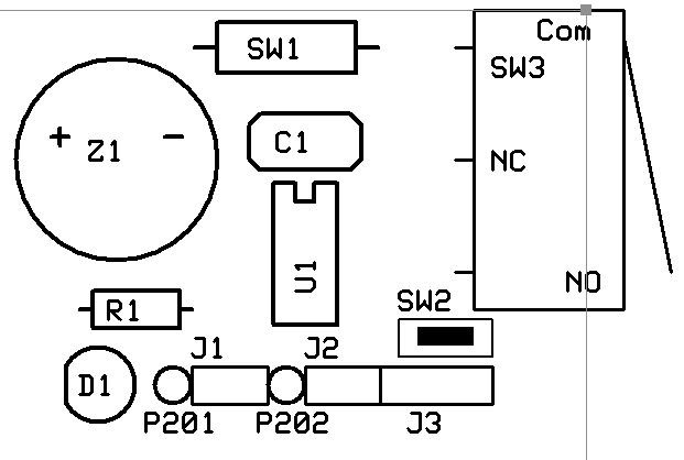
FIGURE 6. For flexibility, the board contains extra component mounting holes. This allows the PCB to be used in other applications that require a simple eight-bit PIC microcontroller.
Summary
As I noted in the beginning, the purpose of the project was to increase my son’s interest in science and to expose him to the engineering process. The project was unquestionably worth the effort.
As I write this article, my son is working on grading final projects for his high school class in introductory computer science. Those students have a teacher with a passion for educating and with a strong background in the practical uses of computer code, as well as an appreciation for what it takes to make computer code practical for general users.
Perhaps some of his skills can be directly traced back to my guidance during the Super-Secret Invisible Burglar Alarm project.
My contribution to his success as a teacher is obviously small, something like the energy in a single electron compared to the total output of Hoover dam. But hey, I think it still counts. NV
A Note about the PCB
Like most PCB suppliers, the one I used had a minimum order requirement; in this case, five boards. I likely would have no use for the extra boards, so I decided to give the PCB a bit more flexibility for future project use, as well as design in some flexibility for the final implementation of the safe project.
For example, the reed switch is mounted directly on the PCB. I had a couple of different reed switches in my spare parts bin; both were about the diameter of a 1/2W resistor, but they had different lengths: 0.4” and 0.6”. To accommodate a variety of lengths, I purposefully placed two pads 0.1” apart on both the anode and cathode sides of SW1. This way, you pick your holes based on reed switch length.
Note that the third hole on the ground terminal of the reed switch is actually to run up to the level switch used to detect the door opening. The lever switch is physically mounted to the PCB via screws, but the electrical connections for the switch need to be wired in place.
In some packaging configurations, the user may not be able to use the planned circuit board locations for either the reed switch or the door switch. Therefore, both switches have traces to a standard 0.1” two-pin header on the PCB, making it quick and easy to connect a remote switch if needed.
The door switch connector (J3) also has a connection for remote power input, which would have been used to connect to a wall wart for other applications or if the safe project started to eat too many batteries.
Unused areas of the board were filled with standard 0.1” thru holes to allow for additional components of future projects.
Resources
https://www.microchip.com/wwwproducts/en/PIC12F629
https://www.digikey.com/products/en/integrated-circuits-ics/embedded-microcontrollers/685?k=12F629
https://en.wikipedia.org/wiki/Reed_switch
https://www.littelfuse.com/products/magnetic-sensors-and-reed-switches/reed-switches.aspx
https://teachkidsengineering.com/introducing-kids-to-electronics
Parts List
| Name |
Description |
Notes |
| U1 |
PIC12F629 |
Microcontroller, Eight-pin DIP Version |
| SW1 |
Reed Switch |
Normally Open |
| SW2 |
PCB Pushbutton |
Normally Open, PCB Mounted |
| SW3 |
Lever Switch |
Normally Open, for Use as Door Sensor |
| C1 |
1 µF Radial |
|
| Z1 |
5V Piezo Buzzer |
PCB Mounted, 0.3” Terminal Spacing |
| Bat1 |
Battery Pack |
Holder for Three AA Batteries (4.5V total) |
| J1-J2 |
0.1” Header, two-pin |
Optional (see text) |
| J3 |
0.1” Header, three-pin |
Optional (see text) |
| D1 |
LED, Red |
Optional (see text) |
| R1 |
280Ω, 1/4W |
Optional (see text) |
Downloads
What’s in the zip?
Code Files