After a 50 year hiatus, I renewed my interest in ham radio and erected two antennas in the woods behind my townhouse. One was a four-band fan vertical (a quad vertical array [1]) and the second was a half-wave dipole. To select between the two, I waterproofed a mechanical coaxial switch and tie-wrapped it to a tree in the backyard [2]. While the switch worked well, it was terribly inconvenient to use — especially in bad weather or at night.
After a year of operation, I began looking for a replacement using wireless technology that could be operated remotely from my shack. At the same time, I decided to add a second dipole. With the additional dipole, I needed a switching scheme that would allow me to select one of the three antennas; switch my balun between the two dipoles; and perform all of this from the comfort of my shack.
I developed a few requirements for my new project:
- Use wireless technology to select one of three antennas from my basement-level shack (below ground) to a switch box 55 feet away.
- Withstand all weather conditions: driving rain; ice and snow; and freezing temperatures.
- Operate remotely from a 12 volt battery.
- Operate at the full legal power limit on SSB with a 50% operator duty cycle.
- Operate from 80 through six meters.
- Display the selected antenna.
Switch Box Design
My plan was to use a wireless relay to select one of two high current capacity power relays. The power relays (capable of handling the full legal limit) would then perform the actual balun and antenna switching. This approach required a dual-channel wireless relay, with one channel assigned to each power relay.
After researching wireless relays on the Internet, I purchased a two-channel DC wireless receiver and transmitter model WR-02, manufactured by AGT (All German Technology).
The unit (Figure 1) came with two remote controllers (transmitters) and one receiver; uses an eight-bit encoding scheme; and transmits at 315 MHz. It has an advertised range of 150 feet.
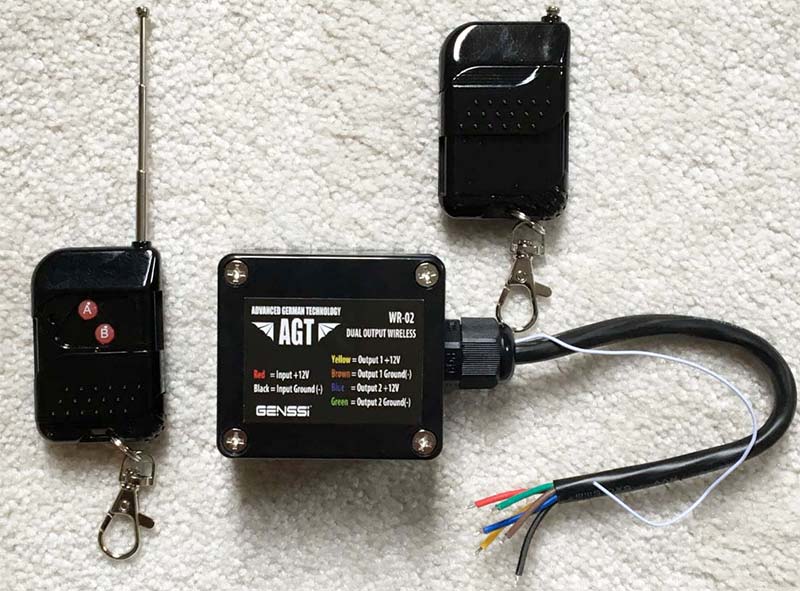
FIGURE 1. Each 315 MHz remote controller (transmitter) is powered by a single 23A/12V alkaline b attery. The receiver (shown in the center) is powered by a 12 volt DC source.
The receiver unit has two channels capable of independently switching five amps at 12 volts DC. Multiple receivers can be reprogrammed to respond to a common set of controllers. When I received the unit, I performed a few characterization tests.
First, I measured the unobstructed clear line-of–sight operating range to be >150 feet. I then verified it operated reliably from my basement-level shack to the intended switch box 55 feet away.
After looking at various power relays, I purchased two 12 volt DC double-pole double-throw 700 Series Magnecraft “IceCube” power relays and mounts, models 782XBXC-12D and 16-782C1, respectively. The relays can be mounted in any orientation, have an AC contact rating of 15 amps, and a pole-to-pole dielectric rating of 2500 volts RMS (3535 volts peak).
Figure 2 shows the schematic of the switching scheme with the wireless receiver; RE1 and RE2 represent the power relays.
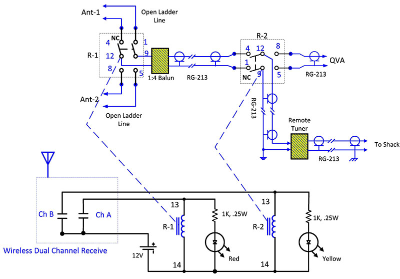
FIGURE 2. Switch box and AGT receiver schematic. The maximum current draw with all the relays and LEDs active is 275 mA.
RE2 is used to route the RF signal from the shack to either RE1 (the dipole leg) or directly to the QVA. When RE1 and RE2 are unpowered, both are in the Normally Closed (NC) state, and Antenna-1 is connected to the shack. Activating Channel A causes RE1 to switch from Antenna-1 to Antenna-2.
Activating Channel B disconnects the dipole leg from the RF path and routes the RF signal to the QVA.
Switch Box Construction
The switch box components (Figure 3) are housed in a 26 cm x 18 cm x 10 cm, Velleman G378 PVC enclosure.
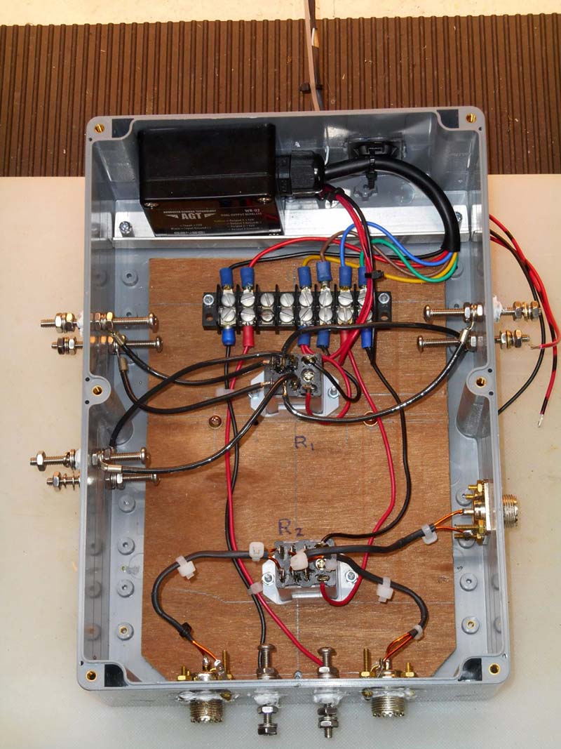
FIGURE 3. The black AGT receiver is shown at the top left; its antenna (white) wire can be seen exiting the top of the enclosure and is attached to a Plexiglas support. Power relays RE1 and RE2 are located along the center line of the enclosure. The three wires shown at the upper right side (red, black, and red-black) power two LEDs (Figure 2) that are mounted in a separate external project box. The LEDs indicate which relay is powered.
The cover (not shown) is gasketed for a waterproof fit. The 8-32 screw-terminal pairs on the left and right sides connect to ladder lines for the two dipoles, and to the balun input (lower left side). I used AWG #14 THNN wire rated at 15 amps to connect the terminals on RE1 to these three ports†.
The SO-239 connector on the bottom left goes to the balun output; the 6-32 screw terminals at the bottom center connect to a 12V 7 Ah SLA battery that powers the entire switch box, including the AGT receiver. The SO-239 connector on the bottom right connects to the input of the remote tuner, while the SO-239 connector at the lower left side is the QVA port. All hardware is stainless steel except for the 4-40 brass hardware used for attaching the SO-239 connectors to the enclosure; 4-40 stainless was out-of-stock at the time, so I purchased the brass hardware instead.
The wire pairs between the terminals of RE2 and its ports, balun output, tuner input, and QVA are all 4.5” long 50 ohm transmission lines constructed from AWG #16 Formvar wire. Transmission lines were used because the port outputs connect to 50 ohm lines (refer again to Figure 2), and I wanted to minimize mismatches where possible. The characteristic impedance of a parallel wire transmission line is given by:
 Equation 1
ϵr is the relative permittivity of the medium equal to 1.0, D is the center-to-center spacing of the conductors, and a is the conductor radius. After trying various materials to achieve the desired impedance, I eliminated the spacing material and placed the two Formvar wires next to each other and secured them with heat shrink tubing and tie-wraps. Figure 4 shows a 9” x 1” x 1/8” Plexiglas L-bracket that provides support for the white AGT antenna wire.
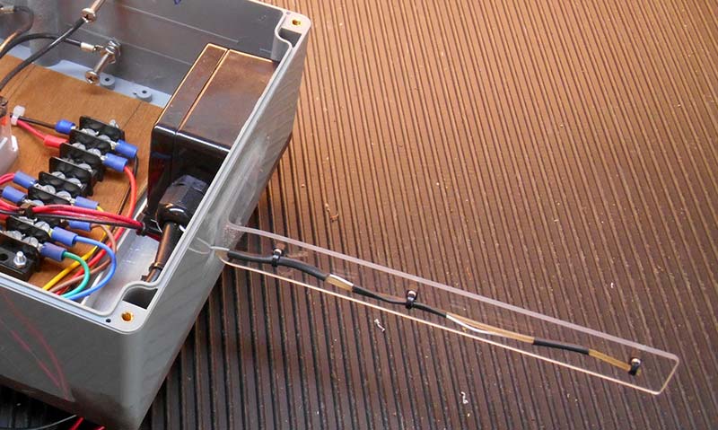
FIGURE 4. AGT antenna and support bracket.
To add stiffness to the wire, a length of 2 mm dia fishing line was placed parallel to the wire and the combination secured with heat shrink tubing. The wire/fishing line pair was then tie-wrapped to the antenna bracket which was hot glued to the enclosure.
The switch box, balun, and remote antenna tuner are all mounted on a 16” x 16” x 3/8” polypropylene cutting board. On the back side of the cutting board, two parallel 1” dia x 12” long PVC tubes placed 3” apart were screwed to the panel to form a cradle which allowed the assembly to be securely mounted to a tree with tie-wraps. Figure 5 shows the back side of the panel with the cradle and external LED display box.
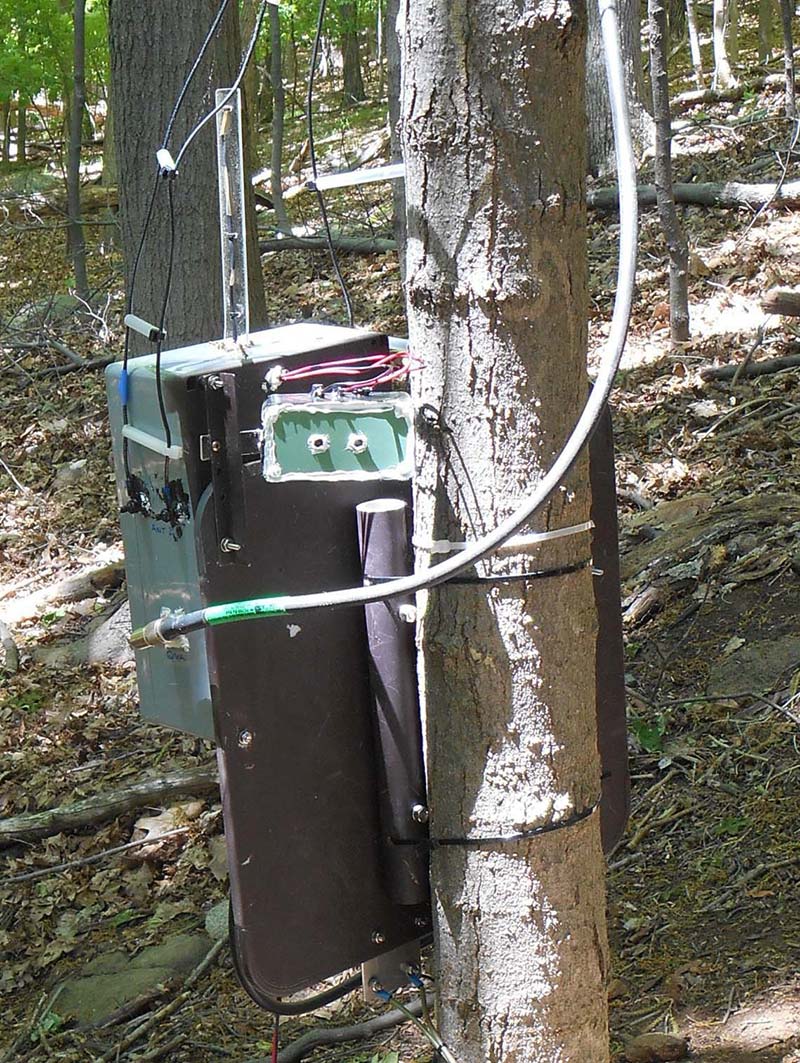
FIGURE 5. Mounting panel with cradle secured to a tree with tie-wraps. The green external display indicates which relays are active and can be easily seen in daylight from my family room window. All external connections to the 8-32 hardware were coated with liquid tape to prevent corrosion.
I use this display as a back-up to verify that the relays are unpowered when I turn in for the evening.
Figure 6 shows the 12 volt 7 Ah SLA battery housed in a water-tight 16 cup Snapware™ food container (9.15” x 7.35” x 5.28”).
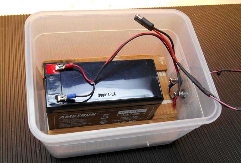
FIGURE 6. The 12 volt 7 Ah SLA battery housed in a Snapware food container.
The lower right-inside of the container was reinforced with a 2” square piece of 1/8” Plexiglas hot-glued to the sidewall.
The reinforced section was drilled and fitted with 6-32 hardware, then wired to the battery terminals and two external wires that provide power to the switch box.
Establishing the Power Handling Capability
The power handling capability of the Switch Box was determined by ensuring that the voltage and current limits of the transmission lines and power relays were not exceeded for a matched (RL = 50) and mismatched load (RL = 1000, SWR = 20:1).
The voltage and current limits for these two components is as follows: AWG#16 Formvar wire in the transmission lines has a dielectric breakdown voltage of 11,300 volts per wire [3] or 22,600 volts between them. The wire is rated for 3.7 amps; to be conservative, I de-rated the current to 1.85 amps. The power relays have a pole-to-pole rating of 3535 volts peak and a contact rating of 15 amps.
To determine the actual voltage and current at the transmission lines and at the relay terminals, I used a loss-less transmission model [4] shown in Figure 7.
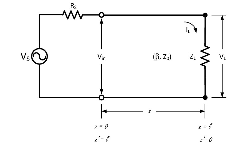
FIGURE 7. A loss-less transmission line was used to model the two 4.5 inch transmission lines in series; l = 9 inches. Vs and Rs represent the open source voltage and source resistance respectively, Rs = 50 ohms.
From Figure 7, the voltage, current, power, and SWR at the load(z’ = 0) are, respectively:
 Equation 2
 Equation 3
 Equation 4
 Equation 5
where
ı = 9” = .229 m, transmission line length.
β =  = Phase constant (radians/s), f is the frequency (Hz), c is the speed of light (3 x 10⁸ m/s), and Vf is the velocity factor.
Z0 = 50, transmission line impedance, ohms.
Γ =  , voltage reflection coefficient with ZL equal to the load impedance.
For a matched load, RL = ZL = Z0 = 50 , Γ = 0, and SWR = 1.0:1. Substituting these into Equation 4 and solving for the source voltage for a 1500 watt load yields VS = 774.5 volts. Substituting VS into Equations 2 and 3 yields the load voltage and load current of 387.25 volts and 7.75 amps, respectively.
When the SSB modal duty cycle of 40% (heavy processing) and operator duty cycle of 50% are applied, the resultant load current is reduced to IL,SSB = 0.4 x 0.5 x 7.75 = 1.5 amps.
The modal duty cycles of CW and digital modes (including FM voice) are 40% and 100%, respectively.
The resultant load currents for these modes with an operator duty cycle of 50% are 1.5 and 3.87 amps, respectively. Since the load current for digital modes exceeds my self-imposed limit of 1.85 amps, the maximum power for digital modes is limited to:

For a mismatched load of RL = ZL = 1000 ohms, Γ = 0.9, and SWR = 20:1. Substituting these values and VS = 774.5 volts into Equations 2 and 3, the load voltage and load current are 737.4 volts and 0.074 amps, respectively.
In summary, the voltages for matched and mismatched loads do not exceed the voltage limits of the power relays or Formvar wire transmission lines.
In addition, the corresponding currents are within component limits, with the exception of the digital modes which are limited to an output power of 685 watts.
Antenna Display
I utilized a second WR-02 in the display design, reprogrammed to respond to the first set of controllers [5]. Two wireless receivers would enable me to switch the antennas with one WR-02 and simultaneously activate LEDs in the display, with the second to indicate which antenna was selected — all with the push of a single controller button.
My display requirements were simple: Indicate which of the three antennas was selected and indicate when both power relays are active. With both activated, only the QVA is connected to the shack, but relay RE1 is active and drawing unnecessary battery current.
Knowing this, I could switch off Channel A (i.e., relay RE1), reduce the current, and increase the time between battery charging cycles.
Table 1 shows the truth table representing these requirements.
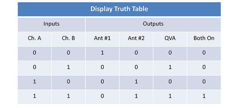
TABLE 1. Display requirements were translated into a truth table. A “0” in the table indicates no activation, while a “1” indicates activation. In the Output, a “1” indicates that an LED is lit.
From the truth table, four Boolean equations were generated; one for each output. The equations (shown below) were then implemented in Resistor-Transistor-Logic (RTL) as shown in Figure 8.
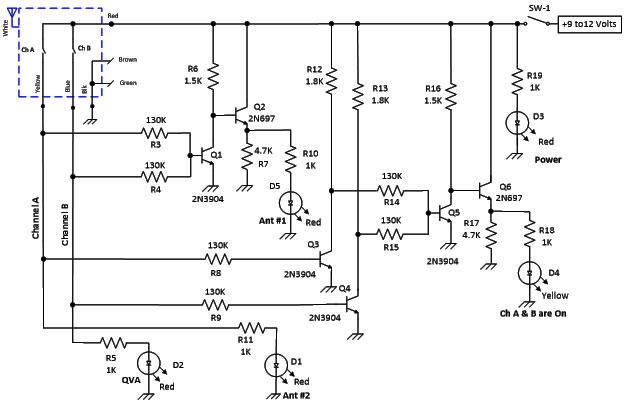
FIGURE 8. Antenna display schematic implemented in RTL logic. The second WR-02 is shown in the upper left corner. All resistors are 1/8 watt.
- Ant #1 = A’ & B’ = (A + B)’
- Ant #2 = A & B’ + A & B= A & (B’+B) = A & 1 = A
- QVA = (A’ & B) + (A & B) = B & (A’ & A) = B
- Both On = A & B =(A’ + B’)’
Transistors Q1 and Q5 are NOR circuits while Q3 and Q4 are inverters; Q2 and Q6 are emitter followers.
The emitter followers were added to provide additional current capability for a potential future display. A nine volt wall wart powers the display.
Figure 9 shows the display wiring built on a portion of a Velleman Eurocard three-hole Island PCB (printed circuit board) and installed in a 5-1/8” (W) x 2-9/16” (H) x 6-1/4” (D) clam-shell project box
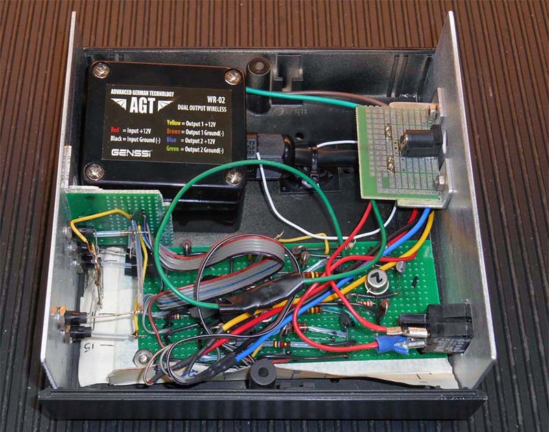
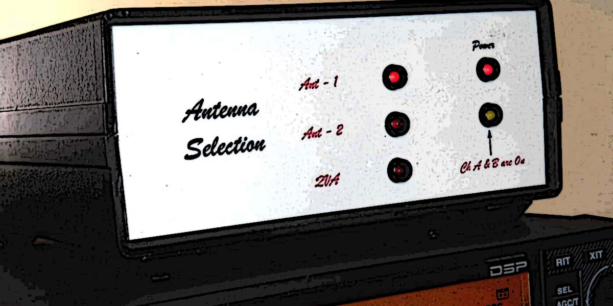
FIGURE 9. Top inside view of the display unit. The rear panel (right) contains the wall wart connector and power switch, while the front panel (left) contains LEDs indicating power on/off, and three LEDs indicating the antenna selection. The second WR-02 is in the upper left corner.
Figure 10 shows the final display.
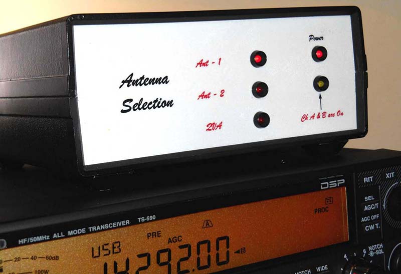
FIGURE 10. Antenna display unit sitting atop my Kenwood TS-590s. Front and rear panel graphics were generated in Microsoft Visio. The “mirror” image of each was printed onto an HP ultra-thin plastic inkjet transparency. After cutting out the graphics, the “ink” side of each transparency was glued to their respective panel using 3M Super 77 multipurpose (spray) adhesive. This produces a scratch resistant display.
Conclusion
The wireless switch box has been a major addition to my shack, allowing me to rapidly switch between antennas during contests or while chasing DX regardless of the weather — all from the comfort of my shack. NV
†THNN wire insulation is rated at 600 volts. The breakdown voltage of dry air is approximately 30KV/cm; derating this to 15 KV/cm to account for high relative humidity provides an additional insulating potential of 19 KV since the 14 gauge wires were spaced at least 1/2” away from other wires.
References
[1] S. Ekiert, “A Stealthy Quad Vertical Antenna,” QST, August 2016, pp 37-40.
[2] S. Ekiert, “Weatherproofing a Coaxial Switch,” QST, Hints and Kinks, February 2017, pp 70-71.
[3] Essex Formvar, Magnetic Wire/Winging Wire, Product Datasheet, https://www.essexbrownell.com/media/cms_content/downloads_links/Essex-Wire-Datasheet-Formvar-EN-062020.pdf.
[4] D.K. Cheng, “Field and Wave Electromagnetics,” 2nd Ed., Addison-Wesley, 1985, Chapter 9.
[5] S. Ekiert, “K3KKH Presents: A Wireless Three-Way Antenna Switch and Display,” FairLawnARC.org YouTube, January 18, 2019.
| ITEM |
DESCRIPTION |
SOURCE |
| WR-02 |
AGT GENSSI, Two-Channel DC Wireless Receiver & Transmitter |
Amazon |
| RE-1,RE-2 |
Magnecraft 700 Series “Ice Cube” Power Relay, DPDT |
Mouser |
| Relay Mounts |
Magnecraft 700 Series “Ice Cube” Power Relay Mount |
Mouser |
| Switch Box Enclosure |
Velleman G378 |
Local electronics store |
| Battery |
Amstron 12 volt, 7 Ah SLA Battery w/F1 Terminals |
Amazon |
| Battery Enclosure |
16 cup Snapware Food Container |
Stop & Shop |
| Circuit Board |
Velleman Eurocard Three-hole Island PCB |
Local electronics store |
| Kitchen Cutting Board |
Oneida 16 in sq Plastic Cutting Board |
Bed Bath & Beyond |
| External LED Display Box |
2” x 4” x 1-1/2 ” Project Box |
RadioShack |