One hobby that’s prevalent today is restoring antique radios. Two such radios are shown in Figure 1 and Figure 2.

FIGURE 1. Philco 1938 console radio.
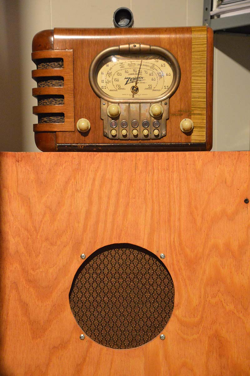
FIGURE 2. Zenith table model radio from the late 1930s, sitting on a speaker box to raise the level of the radio and provide a better speaker for better sound.
The wood on these radios was refinished. They were stripped down to the chassis; the chassis was painted silver; and the tubes, capacitors, and hookup wire were replaced.
Once you have an antique radio, it’s nice to listen to it. Unfortunately, the content of present day AM radio stations leaves a lot to be desired. It’s comprised mostly of religious stations, political talk shows, sports talk shows, and gospel and country music. There’s nothing comparable to the type of programming that was on the air in the heyday of radio broadcasting.
The solution to this dilemma is to use a low power crystal-controlled AM transmitter to broadcast age appropriate material to the antique radio. Such an AM transmitter is the subject of this article. The transmitter can also be used for any other purpose desired. The transmitter is legal to use under FCC part 15 rules because the power is low and the antenna is short.
The Internet is a current source of vintage music and old radio programs. Pandora, You Tube, Google Play, and Spotify are examples of such sources. Most of these sites have free services. Some have premium services for a price.
Sirius XM provides streaming on the Internet for customers that subscribe to their satellite radio service. The Sirius XM channel 73 — “40s Junction” — is appropriate for antique radios. Vintage music can also be obtained on audio CDs and old vinyl records; sometimes from FM radio on audio cassette tapes.
The AM transmitter can get a modulation source from a computer, Internet radio, a smartphone (maybe with an audio Bluetooth adapter), an audio CD deck, an audio cassette deck, or a vinyl record turntable with a preamp. The input to the transmitters is an RCA jack.
A cable with RCA plugs on one end and a 3.5 mm stereo plug on the other end may be necessary for some sources. One unique application is to use two AM transmitters of different frequencies with a stereo source (such as a CD player deck) of vintage style music to broadcast to two separate antique radios providing what could be called antique stereo.
The Transmitter
The oscillator of the transmitter uses one gate of a digital hex inverter as the amplifier. A schematic diagram of the transmitter is given in Figure 3 (and included in the downloads) and a Parts List is provided.
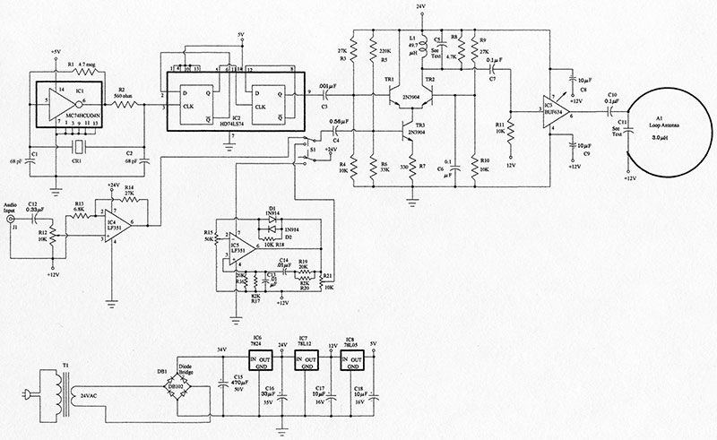
FIGURE 3. Schematic of the AM transmitter.
The transmitter has several unique features. A broadcast frequency is chosen that’s not used by any local or high power station. Because crystals for AM frequencies are somewhat hard to find, a crystal of four times the desired AM band frequency (a shortwave crystal) is used.
A dual D flip-flop is used to divide the frequency by four. The modulator is a modified Gilbert cell with a load tuned to the broadcast frequency. This is followed by a BUF634 buffer amplifier.
The buffer amplifier is fitted with a stick-on heatsink. The antenna is a 1/4 inch copper pipe bent into a circle one meter in diameter. The antenna is tuned to the broadcast frequency by a capacitor in parallel with it. This antenna is much more efficient than a straight wire three meters long. An onboard 1,000 Hz oscillator is provided for testing and a switch is provided to change the oscillator to the audio input of the transmitter. The power supply contains three voltage regulators to provide the three needed voltages: 24 volts; 12 volts; and 5 volts.
Tuned Circuits
There are two tuned circuits in the transmitter for which the capacitance must be calculated based on the AM band frequency that’s chosen. The inductance used in the tuned circuit in the modulator is 49.7 mH. This is made by winding 30 turns of number 24 wire on an Amidon FT-50-61 ferrite core. The equation for calculating the capacitance to resonate with this inductor is:
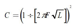
where 2π = 6.28; F = frequency; and L = inductance.
For the inductor given above, the equation becomes:
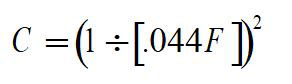
where F = 1510 kHz (1.51 x 10⁶) and C = 224 pF (224 x 10-12 Farad).
The closest standard value is 220 pF.
The inductance of the one meter circular antenna I used measured 3 mH. Thus, the equation for calculating the capacitance in parallel with the antenna is:
where F = 1,510 kHz and C = .00362 µF (.00362 x 10-6 Farad). The closest standard value is .0033 µF.
Choose the closest value of capacitance available. One could use a variable capacitor across the inductances and tune for the maximum output voltage. Keep in mind that small variable capacitors with a capacitance this large are not common.
Parts Procurement
Most of the parts are available from online distributors like Mouser and Digi-Key. The copper pipe for the loop antenna can be obtained at a hardware store. One quarter inch pipe is the type used to supply water for ice makers.
The ferrite core for the modulator inductor can be obtained online from Amidon Associates. While the distributors have crystals, a better supply is available online from the AF4K site. The stick-on heatsink for the BUF634 buffer is available online from Jameco Electronics. The circuit board was made by FAR circuits in Dundee, IL. The common mode choke was a surplus item. It may be omitted if one can’t be found. Simply attach the 24 VAC wires to the AC input of the diode bridge DB1.
Construction
The circuit is built on a 5-7/8 inch by 6-3/4 inch circuit board. The solder side PCB (printed circuit board) diagram is shown in Figure 4.
FIGURE 4. Printed circuit board pattern for the transmitter.
The parts placement diagram is shown in Figure 5.
FIGURE 5. Parts placement diagram for the printed circuit board.
A picture of the completed board is shown in Figure 6.
FIGURE 6. AM transmitter board.
A picture of the loop antenna is shown in Figure 7.
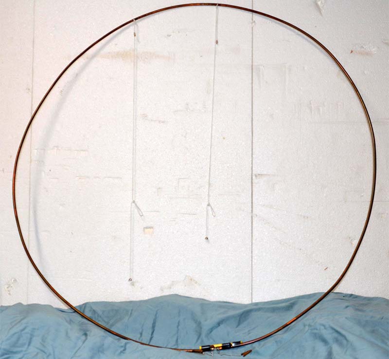
FIGURE 7. The loop antenna.
The termination of the copper pipe of the loop antenna is shown in Figure 8.
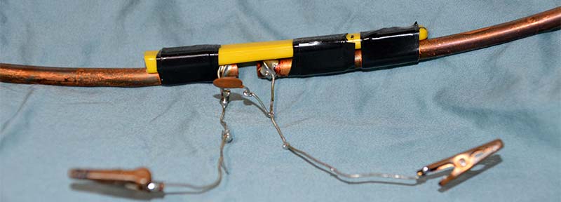
FIGURE 8. Close-up of the loop antenna termination showing the capacitor C11 attached.
The ends of the pipe are secured by taping them to an insulator such as a toothbrush handle. Lead wires are soldered to the ends of the pipe. The lead wires are terminated by mini-gator clips to attach the antenna to the transmitter. The capacitor C11 is attached across the lead wires. The transformer is not mounted on the circuit board but is external to it. The transformer and the circuit board could be mounted on a wooden breadboard.
SetUp
Once the transmitter is built, there’s very little adjustment required. If an oscilloscope is available, the onboard audio oscillator can be switched in and the modulated waveform can be checked. It should look like the graph in Figure 9.
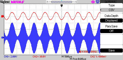
FIGURE 9. Response of the transmitter (bottom trace) to sine wave modulation (top trace).
The top waveform is the modulation signal and the bottom waveform is the modulated output of the transmitter. With music audio into the transmitter, set the modulation level so that the transmitter clips every several seconds.
Music contains a lot of spikes. If the modulation was set so that the transmitter never clips, then the modulation level would be too low.
I hope you’ll consider getting and/or restoring an antique radio. There’s nothing quite like listening to vintage music on vintage equipment. NV
Parts List
| Resistors (All are 1/4 watt) |
| R1 |
4.7 meg |
| R2 |
560 ohm |
| R3, R9, R14 |
27K |
| R4, R10, R11, R18 |
10K |
| R5 |
220K |
| R6 |
33K |
| R7 |
330 ohm |
| R8 |
4.7K |
| R12, R21 |
10K Miniature Trimmer Resistor |
| R13 |
6.8K |
| R15 |
50K Potentiometer |
| R16, R19 |
20K |
| R17, R20 |
82K |
| Capacitors (50 volt Unless Otherwise Specified) |
| C1, C2 |
68 pF |
| C3 |
.001 µF |
| C4 |
0.56 µF |
| C5 |
Depends on the frequency chosen. See section on Tuned Circuits. |
| C6, C7, C10 |
0.1 µF |
| C8, C9, C17, C18 |
10 µF Electrolytic 16 volt |
| C11 |
Depends on the frequency chosen. See section on Tuned Circuits. The capacitor is mounted on the loop antenna, not the circuit board. |
| C12 |
0.33 µF |
| C13, C14 |
0.01 µF |
| C15 |
470 µF Electrolytic 50 volt |
| C16 |
33 µF Electrolytic 35 volt |
| Semiconductors |
| IC1 |
MC74HCUO4N Hex Inverter |
| IC2 |
HD74LS74 Dual D Flip-Flop |
| IC3 |
BUF634 High Speed Buffer |
| IC4, IC5 |
F351 Op-amp |
| IC6 |
7824 Voltage Regulator |
| IC7 |
78L12 Voltage Regulator |
| IC8 |
78L05 Voltage Regulator |
| TR1, TR2, TR3 |
2N3904 Transistor |
| DB1 |
DB102 Diode Bridge |
| D1, D2 |
1N914 Diodes |
| Miscellaneous |
| CR1 |
Crystal for four times the desired transmitter frequency. |
| L1 |
Inductor: 30 turns of 24 gauge wire on a FT-50-61 core. |
| A1 |
Loop Antenna: 1/4 inch OD copper pipe bent into a single circle one meter in diameter. |
| S1 |
DPDT Slide Switch |
| T1 |
Transformer 24 volt secondary, one amp; Mouser 553-F-45X. |
| |
Copperclad Circuit Board 5-7/8” x 6-3/4” |
| J1 |
Circuit Board mounted RCA phono jack; Mouser 490-RCJ-041. |
| |
Power Cord for the transformer. |
| |
Heatsink for BUF634 Buffer IC; Jameco #2213472. |
| CMC |
Common Mode cCoke 3.3 mH per section. |
| |
Two Mini-Gator Clips |
Downloads
What’s In The Zip?
Schematic
PCB Patterns