The MEMO_BOX (Figure 1) is a battery powered, motion-detector triggered, audio record/playback project that will help you to remember what you might forget; be that appointments, taking medicine, etc.
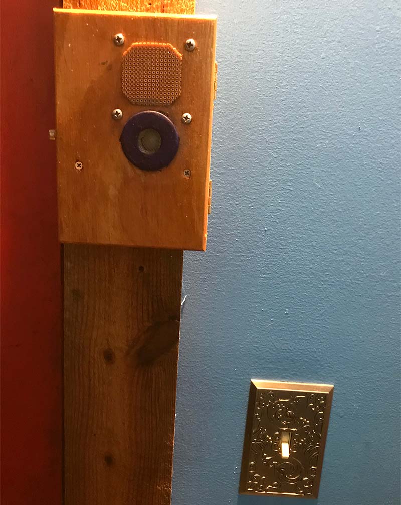
FIGURE 1. The completed MEMO_BOX, mounted on my door frame.
Before you stop reading because you see the words ‘battery powered,’ you should know that this device may well last many months on three AAA batteries, depending (of course) on how often it’s triggered.
I have one next to my front door (Figure 1) on which I record voice messages such as:
‘Do you have your phone and did you take your medicine?’
‘Dentist appointment on Wednesday. Pick up Noah at 3 pm.’
Playback is automatic when I get close to the door. I’ve seen reminder boxes that require pushing a playback button, and I’ll bet a lot of them do not get used. With the motion detector, there is no decision making to ignore.
I have another box along the path through the woods at my home that I use for jokes, like ‘Beam me up, Scotty. There’s no intelligent life here.’ The MEMO_BOX lends itself well to Halloween gags as well.
The MEMO_BOX is made up of the following:
- Parallax motion detector
- Nuvoton I16-COB20 voice recorder evaluation board
- Custom protoboard circuit
- Three AAA batteries in holder, with wires
- Speaker (eight ohms)
FUNCTIONAL DETAILS
The Nuvoton I16-COB20 is a ‘chip corder’ evaluation board that costs less than $7 from Digi-Key. Add a power source and a speaker, and you have everything you need for simple voice recording.
The MEMO_BOX has a RECORD button, a PLAYE button, and a PLAYL button. The difference between the latter two is that PLAYE can be pressed and released for playback of the entire recorded message, whereas PLAYL will stop playback when you release it. Recording stops when you release the RECORD button or when the maximum recording time of approximately 10 seconds is reached. The Parallax motion detector costs about $11 from Digi-Key and is rated at 3-15 VDC. It draws only about 20 µA, which makes it great for battery powered projects. Its output goes HIGH for about three seconds when motion is detected.
It’s quite sensitive; so much so that I had to find a way to reduce sensitivity. Otherwise, it will trigger from 20 feet when a dog walks past, which would soon drive everyone in the house crazy. That might be fine for an outdoor application, but I need it to only trigger when I get close to the front door. Spoiler alert: Covering the motion detector with a piece of nylon window screen works quite well. More on that later.
The custom protoboard serves two functions: power switching in response to a signal from the motion detector; and triggering the PLAYE input on the I16-COB20. See Figure 2 for the schematic.
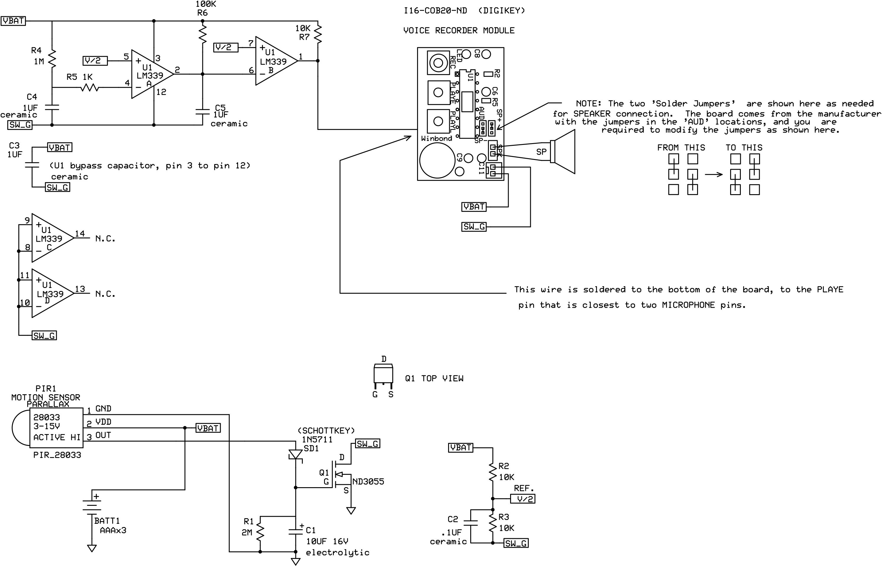
FIGURE 2. Schematic for the MEMO_BOX; created using ExpressPCB.
CIRCUIT DETAILS
The POWER SWITCHING section has the task of applying power to everything except the motion detector, which receives power at all times. The idle motion detector consumes only about 20 µA.
When motion is detected, the HIGH output turns on MOSFET Q1. Most of us are accus-tomed to seeing power switched at the high side (VBAT) with a common ground as the return for all of the circuitry.
Things are done differently here, mainly because I wanted to use one of my N-channel MOSFETS (U1).
Looking at the schematic, the only components connected to ground are the motion detector, R1, and C1. The remainder of the circuitry — including the I16_COB20 chip corder module — have their returns connected to what I call SW_G (switched ground). When MOSFET Q1 is ON, SW_G and battery ground are virtually the same due to the very low ON resistance of Q1.
When Q1 is OFF, current drain is due only to the motion detector.
Q1 turns ON when the motion detector output goes HIGH. The ON threshold of Q1’s gate is somewhere between 1.7 and 2 volts. In addition to turning on Q1, the motion detector output also charges up capacitor C1.
The output of the motion detector goes LOW after about three seconds, so diode SD1 prevents the motion detector from discharging C1 when its output goes low. We need C1 to keep Q1 ON for some desired length of time. We need resistor R1 to slowly discharge C1 so as to turn OFF Q1 at the end of that desired length of time.
Choosing values for R1 and C1 is somewhat critical. If C1 discharges too quickly, we won’t get the maximum 10 second record time that the I16-COB20 offers. If C1 discharges too slowly, we are not only wasting battery power, we’re also extending the amount of time we must wait until the motion detector can re-trigger the I16-COB20. The U1 triggering circuitry around U1 works at power UP, so we must have power DOWN before we can trigger. Values of 2M and 10 µF for R1 and C1 work well. We get an ON time of somewhere between 12 and 14 seconds; long enough, but not excessively long.
The PLAYE TRIGGERING section has the task of triggering playback once and only once after wake-up. (Wake-up is when the motion detector has put its output HIGH in response to detected motion.) The heart of the triggering is the LM339 comparator, of which only two of the four comparators are used. The goal is to wait a few milliseconds after wake-up (with the output of U1B pulled high by R7), then pull the outputs low for several milliseconds, then let it go high again.
This output is wired to the PLAYE switch on the I16-COB20 module, so the high/low/high pulse causes the module to play the prompt one time. After making the pulse, we want the U1A outputs to remain HIGH forever (or until power goes away). It helps to look at the schematic.
There are two timers here: U1B, R6, and C5 (on the right) make the shorter timer that causes the high to low edge (which starts the playback); and U1A, R4, and C4 (on the left) make the longer timer that causes the low to high edge (which ends the pulse).
At wake-up, both C4 and C5 are discharged, so the output at U1B will be HIGH due to the R7 pullup resistor. We need this brief high period after wake-up to give the module time to do whatever reset procedure it needs.
It’s important to remember that the LM339 outputs are open drain, which means it can pull low but not high. This characteristic is exploited at the junction of U1A’s output. Once C4 charges up enough to cause the output at pin 2 to go low, it will remain low until power fails. As a result, we get the desired one (and only one) pulse at the output of U1B, which is tied to the PLAYE input on the I16-COB20 module.
THE I16-COB20
The I16-COB20 requires a modification in order to drive the speaker directly. Again, refer to the schematic in the upper right corner for details. Also see Figure 3A and Figure 3B for photos of the ‘before and after’ modification.
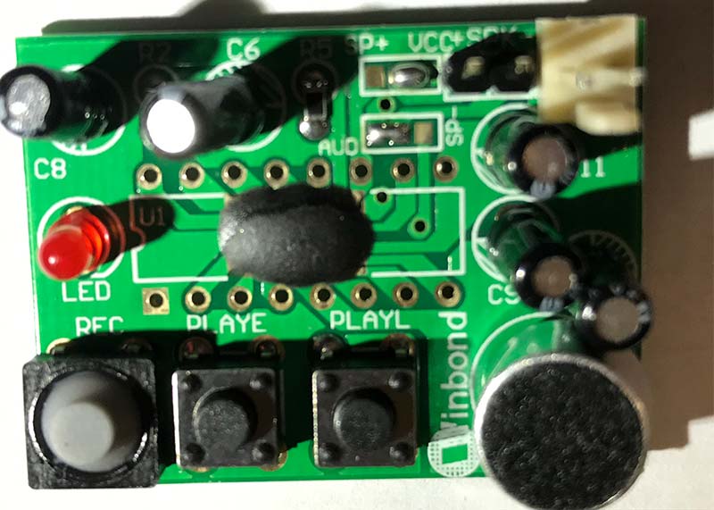
FIGURE 3A. The I16_COB20 module BEFORE modification.
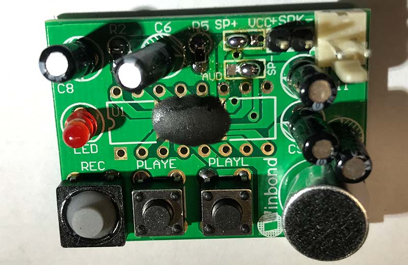
FIGURE 3B. The I16-COB20 module AFTER modification.
It involves moving two solder blobs to opposite pads. (A little flux and some solder wick can help here.)
It’s advisable to test the I16-COB20 first before you do all the other work. I purchased four of them, and one of them didn’t work. All you need for testing are four temporary wires (two for power and two for the speaker). You can use a 5V power supply instead of batteries if desired.
Figure 4 shows this temporary connection for testing.
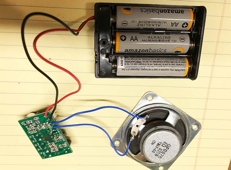
FIGURE 4. The I16-COB20 test setup.
Press the REC button, then the red LED should turn ON to indicate recording. Speak into the microphone, then release the REC button. Next, press and release the PLAYE button, and you should hear your voice played back.
‘The audio quality is poor’ you say, and rightly so. But don’t worry. The enclosure will make a dramatic improvement.
THE ENCLOSURE
I debated building an enclosure from scratch, but fortunately I searched for ‘small wooden boxes’ on Amazon and found one (6” x 4” x 2”) for $6.53 that is perfect for this project. Try entering ‘9151-50’ and scroll down until you see it. (I find it hard to justify buying the hinges, the clasp, and the wood, and then doing all the work, when I can buy one for such a low price.)
THE PROTOBOARD
Another great component for this project is the protoboard used for the custom circuitry. Made by Adafruit, you can get it from Digi-Key for less than $5, using part number 1528-1195-ND. The quality is excellent, and it fits perfectly into the enclosure mentioned above.
CONSTRUCTION
Figure 5 shows the main components placed inside the enclosure.
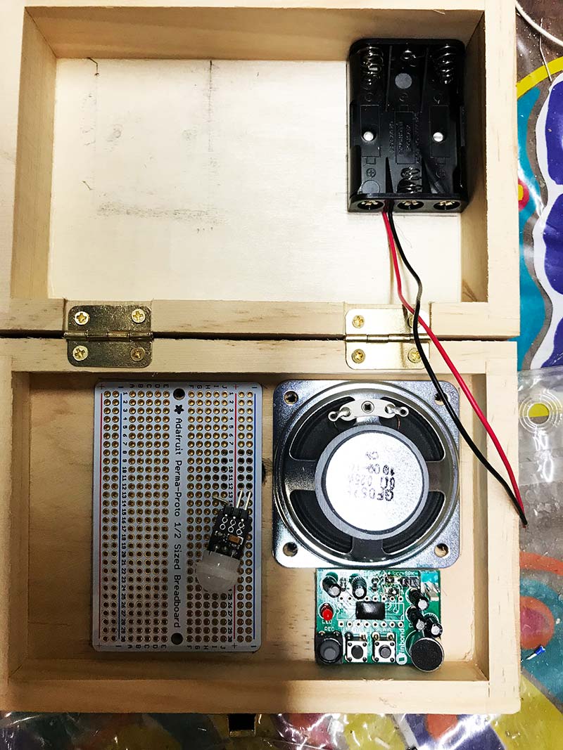
FIGURE 5. Component layout inside the enclosure.
The motion detector will be mounted on the bottom of the protoboard, but I have it lying on top so that you can see what it looks like. I also show the AAA battery holder in the upper left corner, so that you can see it, but it will eventually slide under the protoboard.
I used a pencil to mark mounting holes for the speaker and the protoboard. Allow at least one inch between the bottom edge of the protoboard and the inside edge of the enclosure. That will allow sufficient space to slide the battery holder underneath the protoboard. (I had originally planned to place the battery holder into the other half of the enclosure, but it occurred to me that frequent opening and closing of the enclosure would eventually flex the battery wires to the point of breaking at the solder joint on the protoboard).
On the outside of the enclosure, draw two diagonal lines between the speaker mounting holes. From the intersection, measure out 3/4 inches along each line and make a mark. Then, drill a 1/4 inch hole at each of the four marks and also at the intersection.
Mounting the motion detector with the Adafruit protoboard can be done as described next.
Place the board exactly where you intend it to be. Carefully bend the OUT pin of the motion detector 90 degrees sideways. Place the remaining two pins into the board holes labeled ‘10’ and press just hard enough into the soft enclosure wood to make a mark that you can see. Remove the board and drill a small (say 1/16 inch) hole through the mark farthest from the speaker. Then, close the door and use a 9/16 inch spade bit through the small hole to drill a hole big enough for the motion detector to fit through.
Figure 6A and Figure 6B show the drill holes from the inside and outside of the enclosure.
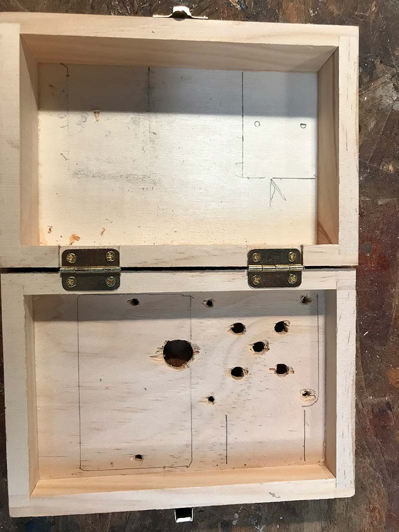
FIGURE 6A. Drill holes seen from inside the enclosure.
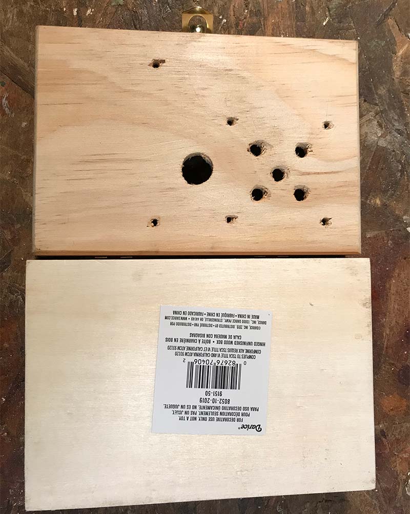
FIGURE 6B. Drill holes seen from outside the enclosure.
One more step before the motion detector can be soldered to the protoboard is that the OUT pin you bent sideways needs to have its end (say 1/16 inch) bent down so as to be in line with the other two pins. Then, all three pins can be inserted into holes on the protoboard.
BE CAREFUL! The motion detector needs to be on the BOTTOM of the board. All the components EXCEPT the motion detector will be on the TOP of the board.
The GND pin should be in the outer hole (labeled ‘-’ in blue); the VDD pin should be in the inner hole (labeled ‘+’ in red); and the OUT pin (which you bent) should be in the hole just below the ‘10’ label. Figure 7 shows the protoboard flipped upside down so that you can see the motion detector mounting.
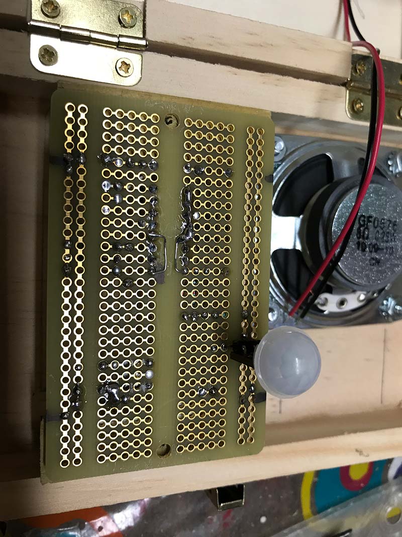
FIGURE 7. Motion detector mounting.
Next, we need spacers to hold the protoboard away from the inner face of the enclosure, so that the dome of the motion detector will be flush with the outer face; 3/4 inch spacing is good for this. You may have screws and spacers to accommodate this.
I made spacers out of wood. A 1x4 piece of pine is exactly 3/4 inches thick, so I cut two pieces 1/2 inch wide and two inches long, and glued them against the inner sides of the enclosure. I then placed the protoboard on top with the motion detector dome in the enclosure hole and drilled two small holes for small wood screws to hold the protoboard in place.
Just take care when you start mounting components onto the protoboard. Leave an open 1/2 inch on the left and right sides of the protoboard because the undersides will be flush against the spacers you glued. Figure 8 shows the homemade wooden spacers.
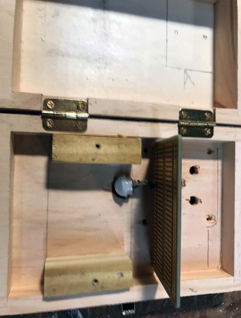
FIGURE 8. Protoboard spacers.
Note that I didn’t make an effort to mount the I16-COB20 or the battery holder. The I16-COB20 seems to fit well next to the speaker, and the wires seem to hold it good enough in place. You might hot glue it in place if desired. The battery holder will simply slide underneath the proto-board.
Wiring the protoboard can benefit from good component placement. By this, I mean that you can avoid a lot of wires by placing the components to take advantage of the protoboard layout. Be sure to jumper wires from the ‘-’ side at the top to the ‘-’ side at the bottom, and the same for the ‘+’ side at the top to the ‘+’ side at the bottom. The ‘-’ side is the battery ground.
One mistake I made was the placement of Q1. Looking at Figure 9, I should have placed Q1 such that the drain tab was above the center line and the gate and source lines below the center line.
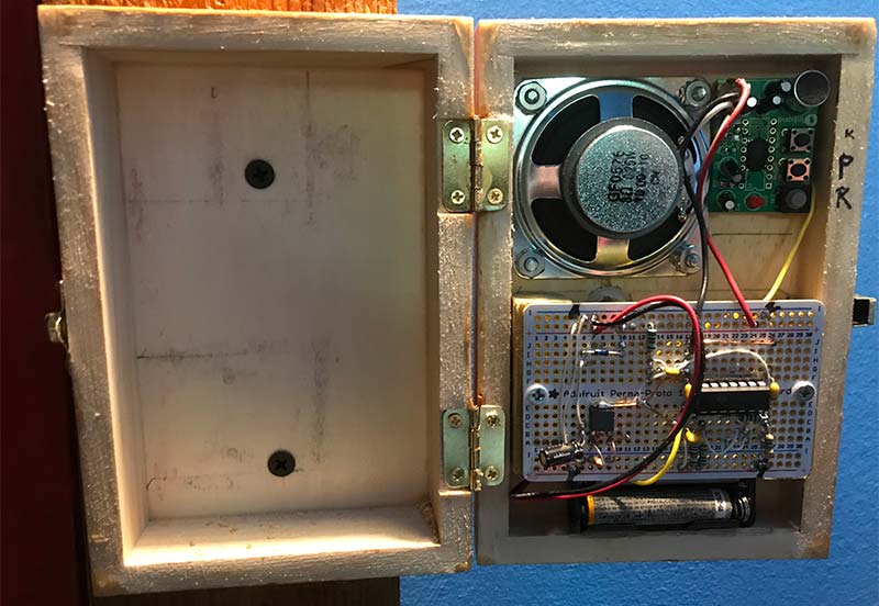
FIGURE 9. Inside view after wiring.
The way I did it, all three pins of Q1 are shorted together because of how the pads are connected together on the bottom of the Adafruit board. It was fixed easily by cutting traces on the bottom of the board with a hobby knife, but next time I’ll do it right.
Another mistake I made more than once while wiring was placing component leads into a ‘-’ hole when, in fact, they were supposed to be going to SW_G. Battery ground and SW_G are NOT the same.
I made the same mistake when I wired the I16-COB20 black wire to battery ground instead of SW_G. This was more serious because it meant that the I16-COB20 was being powered all the time which drains the battery faster, and yet not obvious because the system worked normally when triggered by the motion detector. I noticed it only when I happened to press the PLAYE button and heard the playback even long after Q1 should have turned off.
Keep the wires to the I16-COB20 power and speaker terminals short. That helps to hold the little board in place. The wire from U1 pin 1 to the I16-COB20 can be soldered to the PLAYE pin that is closest to the microphone, which is third pin from the corner. Figure 9 shows the inside after construction is completed.
MOTION DETECTOR SENSITIVITY
The Parallax motion detector is very sensitive; too sensitive, in fact, for my front door MEMO_BOX. I want it to trigger ONLY when I get close to the door; say three feet. I tried several options, including partial covering of the dome and aiming it at different angles.
Eventually, I found that a piece of nylon window screen over the dome works remarkably well. If, however, you are using it for something like a Halloween gag, you might actually want the full sensitivity.
I have one outside that is pointed down at about 45 degrees from horizontal, and I glued a two inch piece of PVC with a 1/2 inch internal diameter to focus the dome and reduce false triggers from things like flickering sunlight due to wind moving tree branches or clouds passing by.
BATTERY LIFE
As mentioned earlier, battery drain is about 20 µA when only the motion detector is powered. After trigger, the circuitry draws about 60 mA while the I16-COB20 is actively driving the speaker with audio, and about 1.1 mA when the I16-COB20 is no longer driving the speaker but continues to receive power until Q1 shuts off. The AAA batteries are rated at 1,000 mAh.
How long should our batteries last? Let’s use the following example. Say the recorded message is five seconds and the message is triggered 10 times per day. During playback, the current drain is 60 mA for five seconds. Then, the current drain is 1.1 mA for the remainder of the ‘power on’ time, for which we will use 14 seconds as a generous example. That means 1.1 mA for 14-5 = nine seconds.
So, five seconds is how many hours?
5 sec * (1 hour/3600 sec) = .0014 hours
Multiply that times 60 mA and we get .083 mAh for the active part of one message. Similarly, nine seconds is .0025 hours. Multiply that times 1.1 mA and we get .002 mAh (let’s say .003 mAh) for the remainder (the quiet part) of the message.
Add those together and we get .086 mAh for one message. For 10 messages, we then have .86 mAh.
The motion detector is powered continuously at 20 µA which is .02 mA, so one day amounts to 24HRs * .02 mA = .48 mAh per day.
In one day, we therefore see current drain of .86 mAh + .48 mAh = 1.34 mAh. So, how many days do we get from one set of AAA batteries?
(1000 mAh/AAA batteries) / (1.34 mAh/day) = 746 days per set of batteries (about two years)
That sounds too optimistic to me, but the point is the batteries should last quite some time. Mine have been going for about four months, so I don’t yet have a real number.
And, of course, if your messages are longer than five seconds or if your box triggers more than our example of 10 times per day, then the numbers go down.
OPERATIONAL NOTES
- There is no volume control. If it’s too loud, then record the message again using a softer voice. The microphone is quite sensitive.
- There is no ON/OFF switch, but you can either remove one battery or even add a switch to interrupt a battery wire.
- There is no ERASE button. If you want to erase the messages without adding a new message, simply press the REC button and release it when the red LED turns ON.
- When you open the enclosure and press the REC or PLAYE button and nothing happens, wave a hand in front of the motion detector. That will power-up the circuit. If you need more time, just do it again every few seconds so that C1 stays charged up and power remains ON. You don’t have to wait for playback to end before you can press the REC button.
- After recording a message, remember that the circuit has to power down before the motion detector will be able to trigger the I16-COB20 again. I learned this the hard way when I recorded a message and then waved my hand repeatedly in front of the motion detector and wondered why I wasn’t hearing playback. You can either wait 14 seconds or press the PLAYE button, but if you stand there forever torturing the motion detector, you’ll never hear playback because you’re keeping C1 charged up with each pulse from the motion detector.
The MEMO_BOX is a fun and handy device that will not only help you remember things you might otherwise leave home without, but can give some good laughs and fun scares to those who walk by it. NV
Parts List
| Reference |
Qty |
Description |
Digi-Key Part Number |
| PIR1 |
1 |
Motion Sensor |
28033PAR-ND |
| BD1 |
1 |
Protoboard |
1528-1195-ND |
| I16-COB20 |
1 |
Voice Recorder |
I16-COB20-ND |
| SP |
1 |
Speaker |
GF0576-ND |
| BATT1 |
1 |
Three AAA Battery Holder W/Wires |
36-2480-ND |
| Q1 |
1 |
Transistor, NTD3055 MOSFET |
NTD3055-150T4GOSCT-ND |
| U1 |
1 |
IC LM339 Comparator |
296-1393-5-ND |
| C1 |
1 |
Capacitor, 10 µF 16V Aluminum Electrolytic |
493-12763-1-ND |
| C2, C3 |
2 |
Capacitors, .1 µF Ceramic |
399-9859-1-ND |
| C4, C5 |
2 |
Capacitors, 1 µF Ceramic |
399-14024-1-ND |
| R1 |
1 |
Resistor, 2M, 1/4W |
RNV14FAL2M00CT-ND |
| R2, R3, R7 |
3 |
Resistors, 10K, 1/4W |
RNF14FTD10K0CT-ND |
| R4 |
1 |
Resistor, 1M, 1/4W |
RNF14FTD1M00CT-ND |
| R5 |
1 |
Resistor, 1K, 1/4W |
RNF14FTD1K00CT-ND |
| R6 |
2 |
Resistors, 100K, 1/4W |
RNF14FTD100KCT-ND |
| SD1 |
1 |
Diode, Schottky 1N5711 |
497-2499-1-ND |
| Enclosure |
1 |
Wooden Box 6” x 4” x 2” from Amazon.com; part number 9151-50 |
|
Downloads
What’s in the zip?
Schematic