Ground faults are a curse to fire alarm systems. Even a small amount of current leaking to ground somewhere in the building can cause an unscheduled fire drill. Worse yet, a second ground fault somewhere else in the building can short out the whole system. That’s why all fire alarm systems have ground fault detection circuits, so the attached building wiring can be fixed before there is a fire.
It was perplexing. I was trying to repair a fire alarm system in a school. The air outside was warm and humid, but inside it was air-conditioned. A light on the fire alarm panel indicated “ground fault” somewhere in the wiring in the building, but my digital ohmmeter claimed there wasn’t any continuity to ground. How was I going to find this conductive path if my ohmmeter couldn’t detect it?
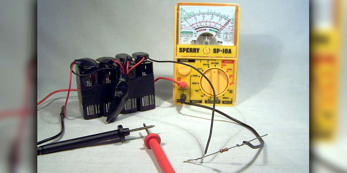
After trying several means of detection, I decided to give my ohmmeter a voltage boost. A couple of 12 volt batteries from my service stock in series with the negative lead of my ohmmeter did that. Now, using about 27 volts of oomph to drive the current of my ohmmeter, it indicated the continuity and I could follow the wiring to find the ground fault. It turned out to be water condensed on a fire alarm pull station in the gym. The humidity from the warm air leaking from the outside through the wall was condensing on the cool air-conditioned switch on the inside. So, why didn’t my ohmmeter show any continuity until it got that extra voltage boost from the batteries?
I was dealing with a voltage based non-linear resistance; a resistance that changes value as voltage changes so current doesn’t seem to follow Ohm’s Law. The resistance of the water condensation was almost infinite for the three volt internal battery of my ohmmeter, but the resistance dropped down to a few thousand ohms when the voltage was increased by the addition of the extra batteries (see Figure 1).
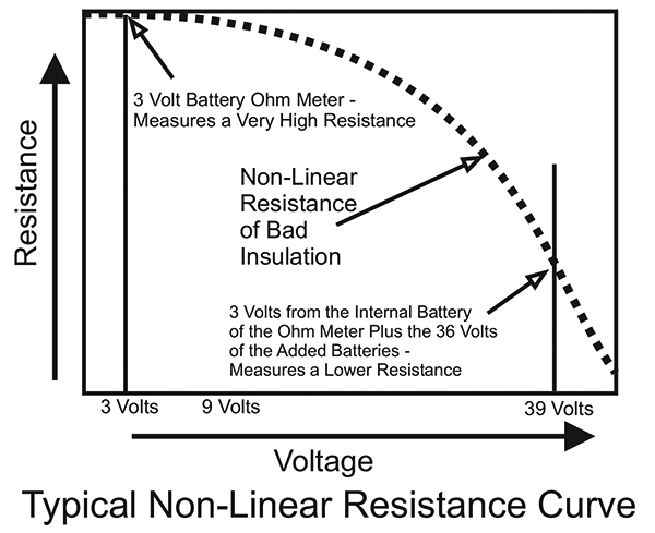
FIGURE 1. This chart shows how a non-linear resistance goes down as voltage goes up. The voltage shown here would be the battery voltage of the ohmmeter.
Non-Linear Resistance
Wire insulation doesn’t have to be smoking before it’s considered bad; it can be slowly breaking down. According to Megger — one of the many manufacturers of insulation testers — causes of insulation breakdown can be electrical stress, mechanical stress, chemical attacks, thermal stress, and environmental contaminations (water condensing on the insulated side of a switch, for instance).
All of these irritants cause voltage-based non-linear resistance — at least at voltages below the smoking stage. The low voltages common to digital ohmmeters show high resistance because the low voltage isn’t enough to drive the current through the insulation. The higher voltage in an insulation tester, on the other hand, is enough to drive the current through the partially broken-down insulation, and the measured resistance is lower. (Refer to Figure 1.)
Insulation Tester
What I had come up with was not a new invention. It was a test instrument used by electricians called an insulation tester which is an ohmmeter with a high voltage internal battery. In the case of the meter assembly I had come up with, the voltage of all the batteries combined was about 27 volts: the three volts of the battery inside my ohmmeter, plus the 24 volts from the two added 12 volt batteries.
I really needed to have one of these testers to carry around with me for this kind of troubleshooting, but nothing was available that I could afford. I would have to craft my own. At first, I tried the digital ohmmeter that I normally used for troubleshooting, and put batteries in series with its leads. When I tested the resistance of the same type of trouble I had encountered — water on the surface of the insulator — the numbers on the display kept changing and were hard to read. It turned out that water is transient so the resistance of water keeps changing slightly up and down. I am a troubleshooter and I wanted to concentrate on troubleshooting, not spend time trying to read the meter, so using the digital meter wasn’t going to work for me.
Next, I tried an old fashioned analog meter that I had lying around. With the extra batteries, the numbers on the ohm scale weren’t accurate anymore, but I could deal with that. At least the needle on the meter didn’t move back and forth very much, and I could get a somewhat stable reading. Then, I thought about voltage. In general, fire alarm systems use 24 volts and I needed to test the wiring at voltages that were higher than that. The 36 volts from four nine-volt batteries seemed to be a reasonable voltage, and the four batteries could be strapped to the back of the meter, so that’s what I used.
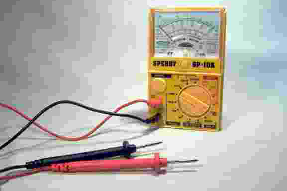
FIGURE 2. Inexpensive multimeter.
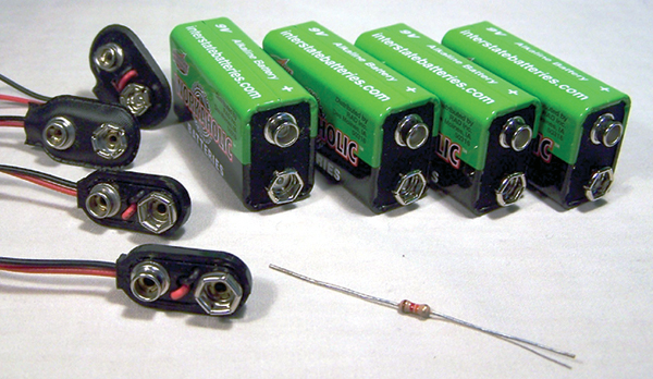
FIGURE 3. Batteries, battery clips, and resistor needed for the project.
The one real worry was that the meter movement would be damaged with excessive current when the leads of the meter — along with the added batteries — were shorted together. To prevent this meltdown, a limiting resistor of a yet unknown value would have to be inserted in series with the added batteries (see Figures 7 and 8). Just to make it easier to calibrate the meter, the value of this resistor would have to be chosen so the meter would read zero ohms when the leads were shorted together — like a normal ohmmeter.
Construction
Start out with the battery clips. Solder the battery clip wires red to black so the batteries are in series. Just don’t cut the leads short. The extra wire will allow for flexing when the batteries wear out and need to be replaced. Individually tape or heat shrink the connections.
For neatness and organization, tape all four batteries together. Connect the clips to the batteries and use tape to make a pigtail of the loose battery clip leads (see Figure 7 again).
Calculating the Value of the Limiting Resistor
The limiting resistor (see Figure 4) makes up for the extra voltage of the batteries. That way, when the test leads are shorted together the ohmmeter will read zero ohms (like a normal ohmmeter). Before proceeding, make sure the ohmmeter is set to the highest ohm scale: RX100 or greater. This is the scale that is going to be used for all future measurements.
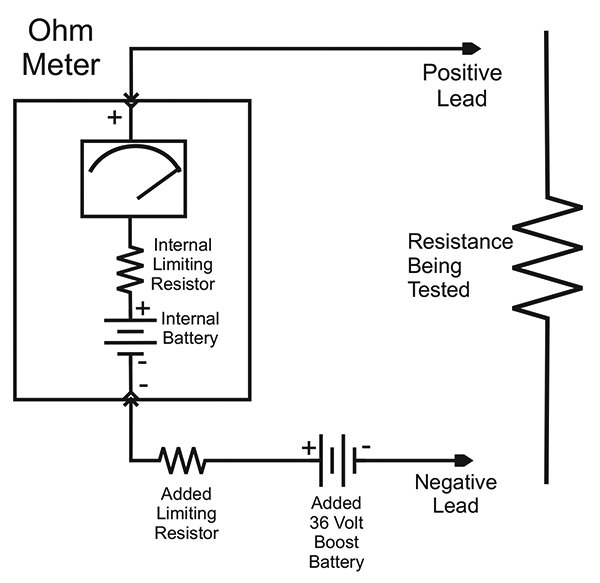
FIGURE 4. Simplified schematic of an ohmmeter showing the addition of the 36 volt batteries and a limiting resistor.
There are two methods of determining the value of the limiting resistor. One is to measure the current that the ohmmeter uses to measure zero ohms, and the other is to experiment to find the value. Both methods work.
Current Method
Measure the current generated by the ohmmeter by placing a digital milliamp meter in series (see Figure 6). The current measured on the ammeter is the current that the ohmmeter calls zero ohms.
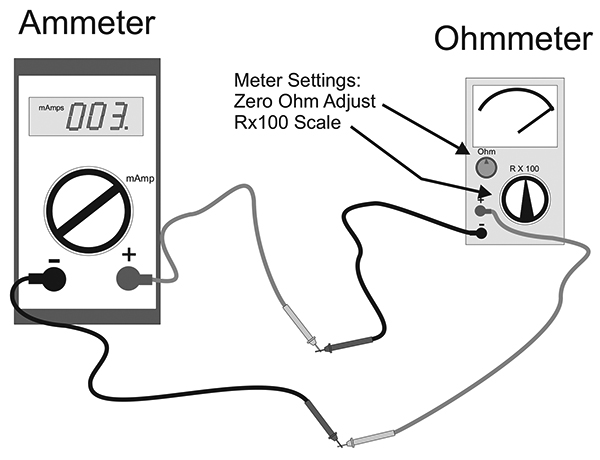
FIGURE 6. Setup to measure the current of the ohmmeter.
My meter requires approximately 3 milliamps to indicate zero ohms. The Ohm’s Law formula (E / I = R) works out to be the 36 volt batteries divided by the .003 amps (3 milliamps) generated by the ohmmeter which equals 12,000 ohms for the limiting resistor.
You can confirm this method has found the proper value for the limiting resistor by temporarily inserting the resistor into the meter circuit as shown in Figures 7 and 8. If the meter can’t be zeroed with the ohm adjustment on the meter, the resistance of the limiting resistor may have to be adjusted using the experimental method.
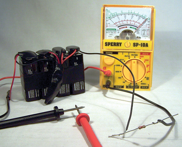
FIGURE 7. Meter, batteries, battery clips, and the shorted test leads.

FIGURE 8. Electro-mechanical layout of all components in the insulation tester.
Experimental Method
Center the ohms adjustment knob on the meter. This will allow the knob to be adjusted either way at a later time. Start out with a 20,000 ohm limiting resistor and insert the resistor into the circuit (refer again to Figures 7 and 8). The needle probably won’t indicate zero ohms, so try a resistor whose value is a little different. Remember, a lower value of resistance will move the needle to the right.
Look at the ohmmeter again. Keep changing the value of the limiting resistor until the needle is close to zero ohms. This will become the limiting resistor. The ohms adjustment on the meter can be used to touch up the needle to point at zero ohms.
Cutting the Negative Test Lead
Use the black probe wire that comes with the meter; it already has connectors. Cut it about seven inches from the end that goes into the meter, and strip the loose ends (see Figure 5). Seven inches should be enough to secure the soldered end to the batteries and still plug into the meter.
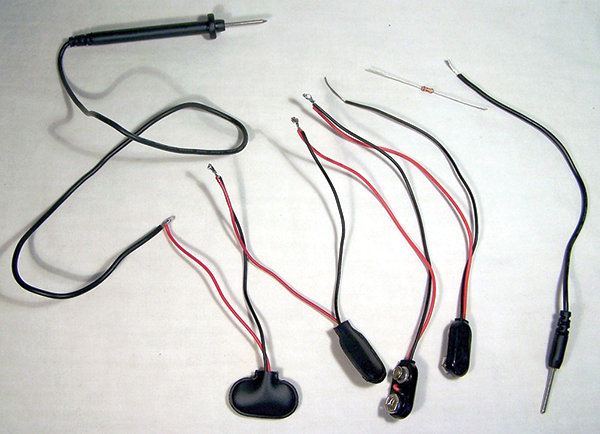
FIGURE 5. Soldered test lead, battery clips, and resistor.
Solder this short lead to one end of the limiting resistor and the other end of the resistor to the positive battery clip lead. Tape or heat shrink the connections.
Solder the stripped end of the long probe wire to the negative battery clip lead (see Figure 5). Tape or heat shrink this connection.
Final Assembly
Tape the limiting resistor and both soldered black test lead ends to the pigtail to give all solder connections mechanical strength. This meter is going to rattle around with the other tools in the tool box, and the solder connections need to be protected so they do not move and break.
This assembly of the batteries and pigtail can be put in a plastic chassis box and then attached to the meter. Personally, I never found a commercial box that was both big enough to house the whole battery assembly and small enough to fit on the back of the meter, so I just used copious amounts of electrical tape to attach the assembly to the back of the meter.
Ohmmeter
Ohmmeters use Ohm’s Law (Resistance = Voltage ¸ Amperage) to figure out the resistance of the device being measured. The voltage is provided by the meter’s internal battery and remains relatively constant. The amperage is the current through the device being tested; in this case, insulation on wire.
On an analog meter (a meter that has a mechanical meter movement), the needle actually shows the amount of current through the device. It moves to the right as the resistance goes down and the current goes up. When the resistance reaches zero ohms (the leads shorted together), the current through the meter is at maximum and the needle is all the way to the right. The numbers on the face of the meter make up a conversion table or cross reference table. It converts the current flowing through the device being measured to the resistance of that device. The numbers on the meter’s face are then multiplied by the switch setting of RX1, RX10, or RX100 to calculate the total resistance being measured. A digital ohmmeter does this cross reference automatically; it converts the test current to resistance to give a direct reading on the display.
Creating a Cross Reference Table
With the added batteries and limiting resistor, the numbers on the face of the meter are no longer factory calibrated. For instance, a resistor under test with my ohmmeter may show 25 on the ohms scale. Normally, this number would be multiplied by 100 (RX100) to represent 2,500 ohms. My meter has been modified, so using a cross reference table I see that this resistor is a 47,000 ohm resistor.
The question: “How do I obtain this cross reference table?” The answer: “Make it.” Each meter is different, so each meter requires its own chart.
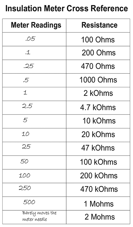
FIGURE 9. Cross reference chart.
To make the chart, choose the values for resistors shown in Figure 9. Then, measure the resistors one at a time, making sure to zero the meter between each measurement. Write down the meter reading for each resistor next to its value. When the table is filled out, it is ready to be used as a cross reference chart.
Just remember to use the RX100 setting on the meter for all resistance measurements. Also, keep in mind that the meter is now applying over 36 volts to whatever is being tested, so make sure there aren’t any delicate electronics in the circuit being measured.
Conclusion
This modified meter is no longer a regular ohmmeter; it’s an “insulation tester.” With a meter like this, I have found wires where the insulation was partially rubbed off; I found a leaky lightning arrestor; I found wire to wire faults inside walls; and I found many instances of water damage. Any fault or conduction that a fire alarm panel detects with its ground fault detection circuit I can now find with this insulation tester.
My old inexpensive analog meter has a use again, and I can easily find wiring faults in a building that can’t be found with a regular ohmmeter. NV
PARTS LIST
| QTY |
DESCRIPTION |
| 1 |
Meter* – Sperry Instruments HSP10 multitester from Home Depot or equivalent |
| 1 |
Resistor Kit** – Digi-Key RS125-ND – 1/4W (.25W), 5%, carbon film, axial lead, 365 pieces (5 ea of 1.0 ~ 1.0M ohms) |
| 4 |
Nine-volt batteries |
| 4 |
Clips with leads for the batteries – Digi-Key 377-1549-ND or equivalent |
| |
Chart paper to make a cross reference table |
| |
Electrical tape |
| |
Solder and soldering iron |
*If you have an old analog meter that isn’t being used for anything anymore, you can use it instead of purchasing a new one. All the meter needs is its internal battery and its test leads.
** Most of the resistors in the kit won’t be used except to calibrate the meter, and the resistors can be reused in future projects. If you have a variety of resistors already, the resistor kit isn’t needed.
CALIBRATING A STANDARD OHMMETER
(VOM, OR VOLT-OHM-MILLIAMP METER)
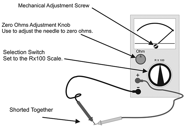
Method for calibrating an analog ohmmeter.
There are only two things to keep in mind when calibrating an analog ohmmeter: the two ends of the scale. The needle points to the left showing infinite ohms (the meter is at rest) when the probes aren’t touching anything, or all the way to the right showing zero ohms (maximum measuring current) when the probes are shorted together. When the two ends are calibrated, the numbers in between take care of themselves. Take a look at the figure.
Step one: Place the meter “at rest” by separating the probes. Turn the mechanical adjustment screw either way to adjust the needle to show infinite ohms.
Step two: Set the selection switch to the desired resistance scale: RX1 (resistance times 1), RX10 (times 10), or RX100 (times 100). In the case of the insulation tester, always use the RX100 scale. Now, short the test leads together. Turn the ohms adjustment knob one way or the other until the needle is exactly over the zero ohms on the meter faceplate.
The meter is now calibrated. This calibration adjustment should be done each time the meter is used to measure resistance, or each time the selection switch is set to a different RX position.
Worst Ground Fault
They tried to use a regular ohmmeter to find the ground fault. I watched them. Right after sunset, while there was enough light to see the cityscape and the lit streetlights, I stood on top of the hill overlooking Duluth, MN. They were power company linemen and they had just driven up to a three-phase, 13,800 volt power pole across the street from a TV station which was off the air because of a power blackout. The lineman in the cherry picker used his ohmmeter to check for shorts in the underground line. A nine-volt battery won’t find much of a problem on a 13,800 volt power line, and that’s what was found — not much of a problem. Well, they put in a new fuse at the top of the pole, turned on the switch, and with the sound of a shotgun and a 15 foot shower of sparks, the fuse blew. All of the city of Duluth went black. There really was a short. A proper insulation tester using a 15,000 volt power source would have detected the problem.
IDEAS FOR THE FUTURE
Switch contacts get dirty and one way of making sure dirty contacts don’t cause a problem is to solder the switch contacts. Of course, this will dedicate the meter and prevent it from ever being used for anything else.
Replacing the internal batteries when the case is taped together can be a real pain. One idea is to remove the battery and replace it with a soldered-in jumper. Then, there is no internal battery to replace.
For those who have real energy, the meter can be backwards engineered and the internal resistors recalculated so the meter can be used on all scales (RX1, RX10, RX100). The resistance scale on the face of the meter will still be off so a cross reference table will be needed, but the meter will be a little more versatile.
Try This At Home

FIGURE A. Testing the resistance of a puddle of water. The probes here are about 1/2 inch apart and both of them are in the water.
Will the insulation tester detect problems that a regular digital ohmmeter won’t? Find out! Try this on one type of insulation problem: water on the wiring.
Spill a little tap water on a clean counter. The puddle should be about one or two inches in diameter. Just don’t add any salt or other contaminants to the water. Measure the resistance of the water using a regular digital ohmmeter, keeping the tips of the probes at least 1/2 inch apart as shown in Figure A. Write down the resistance indicated on the ohmmeter. Some digital ohmmeters will measure infinite resistance, and if that is measured, that’s what should be written down. As a control, find a resistor of about the same value and measure its resistance. Write down that measurement.
Use the insulation tester to measure the same water. Look up the actual resistance on the cross reference table and write down that resistance. The resistance measured by the digital ohmmeter and the resistance measured by the insulation tester will be quite different.
To check the accuracy of the insulation tester, use it to measure the resistance of the control resistor. (Make sure to keep your fingers off the leads because they will corrupt the readings.) Look up the true resistance of the resistor on the cross reference table.
The measured resistance of the control resistor should be about the same whether the digital ohmmeter is used or the insulation tester is used. Water, on the other hand, has a voltage-based, non-linear resistance. That helps explain why the insulation tester — with its high voltage battery — detects a definite problem the water on the insulation, while the digital ohmmeter — with its low voltage battery — shows uncertain readings.
If you really want to have fun with this experiment, try shaking a bunch of salt into the puddle of water and measure the water’s resistance again with both meters.
REFERENCES
EC&M: Insulation Resistance Testing: How and Why?; John A. DeDad
https://www.ecmweb.com/cee-news-magazine-archive/article/20895083/insulation-resistance-testing-how-and-why
Megger: A Guide To Diagnostic Insulation Testing Above 1 kV
https://us.megger.com/products/insulation-testing/dc-diagnostic-insulation-testing/s1-1068-(1)/technical/guide-to-insulation-testing-above-1kv-(1)
Megger: A Stitch In Time
https://us.megger.com/promotion/vf/social-media/stitch-in-time-instant-download
Hyperphysics: Moving Coil Meters
http://hyperphysics.phy-astr.gsu.edu/hbase/magnetic/movcoil.html