One day back in the 1970s, I tuned to a public television station to see an oddly dressed man fighting off a swarm of evil looking robots. It was Tom Baker as Dr. Who saving the universe from the Daleks. I’ve been a fan ever since. For the uninitiated, Dr. Who is a sci-fi show produced by the BBC. Daleks (shown here) are half-robot aliens that roll around saying things like “You will be exterminated!”

Recently, I came across a talking Dalek toy for sale on-line. Of course, I had to get one. Daleks have a bizarre voice, and I thought it would be fun to build a voice-changer circuit to make me sound like one (see the sidebar on voice changer circuits).
With a little research on the Internet (e.g., look up “Daleks” on Wikipedia), I found out that the Dalek voice is produced by mixing an actor’s voice with a fixed frequency sine wave in a ring modulator (also called a balanced modulator). I found different values for the frequency of the sine wave in different sources; the range was 30 Hz to 100 Hz. Using an oscilloscope to actually look at the voice signal from my talking Dalek toy, I saw the typical double sideband suppressed carrier (DSB-SC) wave form produced by a balanced modulator. Figure 1 shows a simplified version. The outer envelope would be the low frequency sine wave while the inner signal would be the voice.
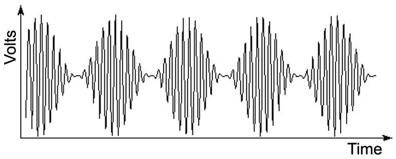
FIGURE 1.
DSB-SC
Balanced modulators are used in RF work to generate and detect signals. (When used in a detector, it’s usually called a mixer.) DSB-SC is basically an AM signal, but without the carrier. Its output contains sum and difference frequencies only, which it achieves by multiplying the audio with a fixed frequency carrier.
A balanced modulator can be built in several ways. You can use an IC such as the old LM1496 which was designed for this purpose. Or, you could use a multiplier IC, such as the AD633. The 1496 requires +12V, -8V, a fist full of resistors and capacitors, and a carefully adjusted trimpot. The 633 is relatively expensive ($8), but luckily, there are other ways to do it.
Figure 2 shows a classic four-diode ring modulator.
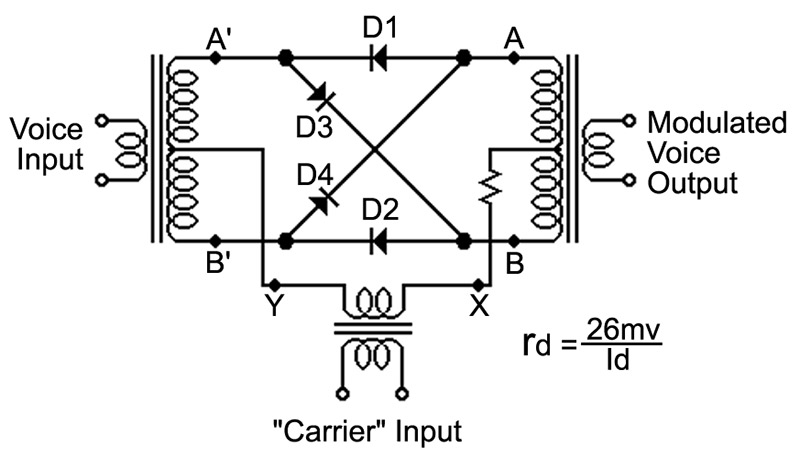
FIGURE 2.
While at first glance it looks like a bridge rectifier, closer scrutiny shows the diodes are not arranged to rectify. Rather, the diodes are used as switches. Remember that the dynamic resistance (rd) of a diode is approximated by rd = 26 mV/Id.
With no current (Id = 0), rd is very high and the diode switch is open. If Id becomes, say, 10 mA then rd becomes 2.6 Ω and the diode switch is closed. The carrier input supplies the diode current.
Referring to Figure 2, if point X is positive with respect to point Y, diodes D1 and D2 conduct and connect points A to A’ and B to B’, thus allowing the input to flow to the output. But if point Y is positive with respect to point X, diodes D3 and D4 conduct and connect points A to B’ and B to A’. Now the input flows to the output but with a 180° phase shift. In effect, the input is multiplied by -1 and is inverted. The audio is multiplied by the carrier input. Note that the carrier current is a bipolar square wave (switches between +I and -I); you want those diodes to open and close quickly and cleanly.
Assuming all the diodes are closely matched and assuming the transformer center-taps are exactly in the middle, then the current from the carrier input will flow equally both ways from the middle of the transformers. That means there is no net flux in the transformers from the carrier, so it doesn’t couple to the output; the carrier is suppressed. (In real life, some carrier will leak through; but with good design, you could get 60 dB of carrier suppression.)
I didn’t want to just build a circuit with three audio transformers. What else is there? Well, another diode switch type of circuit is a balanced bridge modulatoras shown in Figure 3.
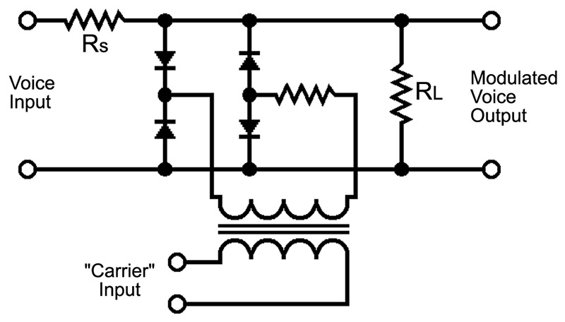
FIGURE 3.
Resistors RS and RL form a voltage divider with RL » RS. With the diode switches open, the output is Vout = [ RL / (RL + RS) ] x Vin » Vin. With the diode switches closed, a very low resistance (RD) is in parallel with RL. Since RD « RL, we have Vout » (RD / RS) x Vin » zero. This circuit effectively multiplies the voice signal by a unipolar square wave (switches between +I and 0): half the time Vout » Vin; and half the time Vout » 0.
Figure 3 is easier to build than Figure 2, but it still requires a transformer. However, if multiplying by a square wave will do the job, why not use an analog switch IC? Such ICs are inexpensive, and no transformers are required.
The Circuit
Figure 4 is a schematic of the voice changer.
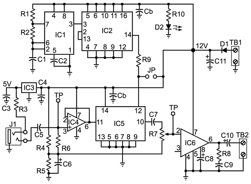
FIGURE 4.
A DC supply is connected to tie-block TB1. Diode D1 protects against reverse polarity. (I’ve learned the hard way that such protection is a good idea.) D2 is a green LED power indicator. Capacitor C11 decouples audio from the power rail. IC3 is a 78L05 to supply a regulated +5 volts to an electret microphone which plugs into 3.5 mm stereo jack J1. R3 connects the five volt bias to the microphone’s built-in amplifier (see symbol in Figure 5) and also sets its gain.
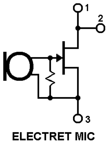
FIGURE 5.
IC4 needs both positive and negative supply rails. Since we are using a single voltage to power the board, we need to create a separate audio ground at half the supply voltage. That’s done with 1% resistors R4 and R5. With respect to audio ground, actual ground looks like a negative voltage. Capacitor C6 decouples the audio ground by creating a low impedance AC path to actual ground.
The power supply you use for this project should be well regulated. Any hum on the DC from the AC mains will be amplified. C11 is there to remove audio; it’s not big enough to remove AC mains hum. To use an unregulated wall-mount supply, you could use the circuit described in my upcoming article on switching regulators.
The voice signal from the microphone is coupled via C5 to buffer op-amp IC4. Since an electret mic produces a relatively large signal, IC4 is configured for unity gain. To use a crystal type mic, IC4 would need to be reconfigured to supply some gain. R6 references the input of IC4 to the audio ground. Note that C5 allows the mic to use real ground while IC4 uses audio ground. The output of IC4 goes to IC5, a CD4066 analog switch. I used a 741 for IC4 because they’re inexpensive, easily obtainable, and I had a bunch. You can use a better op-amp (e.g., LF411) if you have them.
IC1 is a CMOS 555 timer chip running as an astable. IC2 is a CD4027 dual JK flip-flop which divides the 555 output by four to produce a square wave. You can set the frequency that sounds best to you with C1. I used 0.022 µF to get a carrier frequency of about 50 Hz.
The Q output of IC2 is the control signal for the analog switch, so it’s the “carrier” that modulates the audio by turning the switch on and off. The modulated audio from IC5 goes to power-amp IC6 via potentiometer R7, the volume control. Note that R7 is also referenced to audio ground. C7 is required since the input of IC6, an LM380, is referenced to actual ground. The modulated audio output is capacitively connected to a loud speaker via terminal block TB2, and easily drives an 8W speaker.
JP (see Figure 6) is a removable jumper on the printed circuit board (PCB) that allows the supply voltage to be applied directly to the control input of IC5 (pin 12). That has the effect of overriding the modulation from IC2 and forcing the analog switch to remain closed. Resistor R9 is required to isolate the output of IC2 when the jumper is in. With the jumper out, R9 has no effect since IC2 and IC5 are CMOS chips. With the jumper in place, the voice changing effect is disabled and the board performs as a plain audio amplifier. The jumper mounts on a two-pin header soldered to the board.
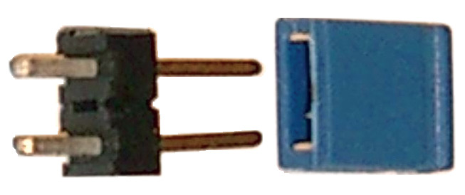
FIGURE 6.
Construction
The PCB (DLKV) is double sided and measures 2.5 by 3.2 inches. The layout of the component side is shown in Figure 7. Four 1/4” corner holes provide a way to mount the board. Power is run separately to the input and power-amp sections to avoid feedback through the power rail. Likewise, each section has a separate connection to ground.
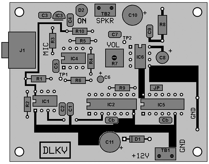
FIGURE 7.
Test Points
I’ve learned over the years that it’s very useful to design test points into PCBs. This board has two test points. TP1 allows you to connect a scope and look at the signal coming from a microphone. TP2 allows you to look at the signal going into the power-amp. It’s also helpful to provide a convenient bus to connect the ground leads of multimeters and oscilloscopes. There is a strip of copper near the edge of the board that connects to ground. There is a hole at each end of the strip. Take a bare piece of solid wire, make a 90° bend in both ends, and solder it to the holes so that the wire is spaced about 1/4 inch above the board. There’s your ground bus.
Using IC Sockets
When assembling a newly designed PCB, I use sockets for the ICs in case I blow a chip due to a layout error. Once I know the board design is okay, I solder the chips directly to the board. Sometimes I’ll keep a chip such as an op-amp in a socket so that I can swap in various types to see if there is any difference in performance.
Mounting in an Enclosure
Microphone jack J1, volume control R7, and jumper JP are all board-mounted. To mount the project in an enclosure, they must be replaced with panel-mounted types and connected back to the PCB with short lengths of hook-up wire. You would replace JP with a switch.
Testing
Before applying power, clean the board with rubbing alcohol and an old tooth brush and give it a careful visual inspection. Look for the usual suspects:
- Bad solder joints
- Broken copper traces
- Shorted copper traces (especially IC pads)
- Reversed polarity on capacitors
- Wrong value capacitor
- Diodes in backwards
- ICs in backwards
- Wrong IC in a socket
- IC socket lead bent under and not in hole
- Missing components (especially monolithic caps)
Once you’re sure there are no obvious problems, measure the resistance from +V to ground. If it’s low or zero, there’s a problem. Assuming you used sockets, pull the chips out one at a time. If the short goes away, you’ve located the problem area. If it doesn’t go away, look for shorted traces.
With the jumper in, set volume to minimum, plug an electret mic into J1, attach a loudspeaker (or headphones), and attach 12 volts to TB1. Make sure the loudspeaker is pointing away from the microphone. Verify that the LED is lit.
Speak into the microphone as you gradually increase the volume to a comfortable level. Verify that the circuit is amplifying. Then remove the jumper as you continue to speak and verify that your voice is modulated.
Wrap-Up
Some fun things you can do with this project are to put “LEAVE A MESSAGE OR YOU WILL BE EXTERMINATED!” on your answering machine or tell the neighbor “GET YOUR DOG OFF MY LAWN OR YOU WILL BE EXTERMINATED!” The possibilities are endless. NV
Parts List
| ITEM |
DESCRIPTION |
| IC1 |
555C Timer |
| IC2 |
CD4027 Dual JK Flip-Flop |
| IC3 |
78L05 5V Regulator |
| IC4 |
741 Op-amp |
| IC5 |
CD4066 Analog Switch |
| IC6 |
LM380 Power-Amp (eight-pin DIP) |
| R1, R2 |
121K, 1%, 1/4W |
| R3, R6, R9 |
15K, 5%, 1/4W |
| R4, R5 |
2K, 1%, 1/4W |
| R7 |
25 kΩ, Single-Turn, PCB-Mounted Potentiometer |
| R8 |
2.7 Ω, 5%, 1/2W |
| R10 |
1 kΩ, 5%, 1/4W |
| C1 |
0.022 µF, Monolithic Ceramic |
| C2, C4, C9 |
0.1 µF, Monolithic Ceramic |
| C3, C5-C7 |
1 µF, Monolithic Ceramic |
| C8 |
10 µF, 25V, Aluminum Electrolytic |
| C10 |
100 µF, 35V, Aluminum Electrolytic |
| Cb |
0.1 µF, Monolithic Ceramic for Bypass (decoupling) |
| D1 |
1N4001 |
| D2 |
GRN LED |
| JP |
Two-pin Header and Removable Jumper |
| J1 |
3.5 mm Stereo Jack, PCB Mounted |
| TB1, TB2 |
Terminal Block, PCB Mounted, Two Contacts, RadioShack part 276-1388 (also Molex 39890-0302 or equivalent on 0.2 inch spacing) |
Voice Changer Circuits
Voice
How is it that we can recognize a person by their voice? You could answer that each person’s voice has a distinctive pattern of qualities that we can hear. But how would you quantify those qualities so that they could be measured objectively? One answer is summed up by the word spectrum.
A microphone converts voice into AC signals that we can observe with an oscilloscope. For example, four spoken words might look something like Figure SB1.
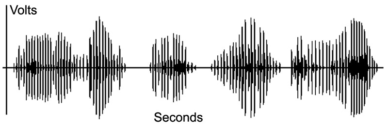
FIGURE SB1.
We can see some sort of pattern in Figure SB1, but how do we get our hands on it? After all, to make a voice changer we need to alter the pattern so it sounds like someone else spoke the words. Which brings us back to spectrum.
Frequency Spectrum
Obviously, the signal in Figure SB1 is some complicated function of time. But back in 1807, a fellow named Joe Fourier wrote a paper showing that, mathematically, such complicated signals can be written as a sum of simple sine waves. Each of the component sine waves would have a specific amplitude and frequency. Just like the rainbow of colors in white light, that collection of sine waves is the frequency spectrum of the signal. Because of slight differences in our vocal systems, when I say the word “tomato” it will have a slightly different spectrum than when you say “tomato.” Our brains can distinguish those differences.
Changing a Voice
So, to make a voice changer, all we need to do is take the signal from a microphone, alter its frequency spectrum, and put it out a loudspeaker. How can we do that? Let’s look at a few techniques (there are more than these).
Compression
One aspect of voice that contributes to its spectrum is dynamic range: As we speak, our voice gets louder and softer. If we never varied the loudness of our voice, it would sound mechanical. So, one technique for voice changing is to use compression. With an automatic gain control (AGC) circuit, we can amplify a signal when it’s soft and attenuate it when it’s loud. AGC circuits are commonly used in commercial two-way radio systems used by emergency person
Figure SB2 shows one way of making a compressor. It relies on our old friend, the diode. The amplifier is set to a fixed gain. The input goes through a voltage divider formed by resistor R1 and rd, the dynamic resistance of the diode. The current through the diode (Id) is controlled by the amplitude of the output, and rd = k / Id. (This is a conceptual circuit; more is required to make it practical.)

FIGURE SB2.
Fuzz
In two-way radios, they want to preserve the quality of the audio so that it’s understandable. But in a voice changer, a little distortion might be a good thing. So in addition to AGC, we can add a little “fuzz” to our voice by clipping the peaks of the sine waves by using a limiter. Clipping makes the sine waves look more like square waves, which adds high-frequency harmonics to the voice signal. Figure SB3 shows a simple limiter circuit. Using three-diode strings in the feedback path makes it a soft limiter, meaning that the corners of the wave tops are rounded. A hard limiter would produce an actual square wave.
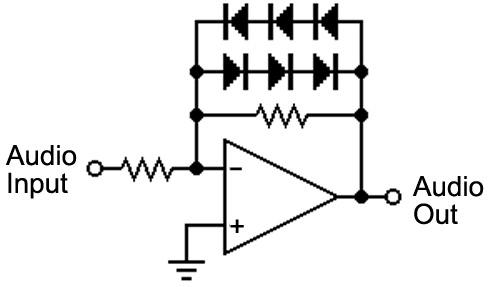
FIGURE SB3.
Resonance
Some interesting effects are produced by inserting a resonant peak into the middle of the audio spectrum. This can be done with a Wien-bridge circuit as shown in Figure SB4. The negative feedback is set to a level high enough to prevent oscillation. As you decrease negative feedback, the effects become greater.
With proper resistor values in the negative feedback path, you will avoid oscillation over the range of the potentiometer. Adjusting the feedback sets the Q of the circuit, and that sets the bandwidth.
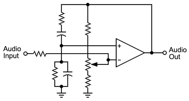
FIGURE SB4.
Mixing
Using band-pass filters, the audio spectrum can be divided into several subranges. The amplitude of the signals within each band can then be adjusted to change the sound of the voice (see Figure SB5). This is what is done at a mixing desk in a recording studio, where the term “mixing” refers to a linear process of addition. The mixing done by a modulator is a non-linear process of multiplication. Non-linear mixing creates new frequencies; linear mixing does not.
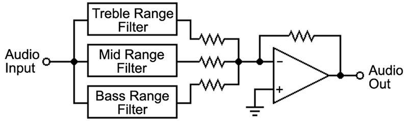
FIGURE SB5.
Holtek HT8950 IC
The HT8950 “Voice Modulator” was designed to be used in voice changers. It allows you to shift the entire voice spectrum up or down in frequency. It can provide an 8 Hz vibrato. It can also create what they call a “robot voice.” The schematic in Figure SB6 is adapted from the HT8590 datasheet. This chip is found in several voice changer kits currently being sold.
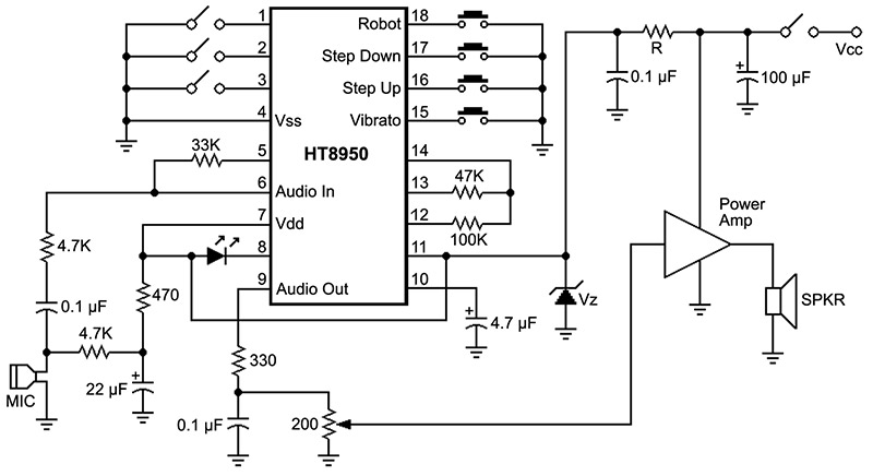
FIGURE SB6.
Other ICs
Princeton Technology makes the PT2399 “echo audio processor” IC which (as you might guess) adds echo to an audio signal. The amount and duration of the echo can be adjusted. It uses A/D conversion, digital delay, and then D/A conversion. Other companies make similar devices.