Are you bored with conventional two-dimensional circuit layouts, or looking for a way to add an artistic flair to your next project? Point-to-point circuit construction has been around for decades, but it usually uses supporting structures like terminal strips that are functional but not pleasing to the eye. I’ve taken the point-to-point construction style a step further by making it self-supporting, which opens up a wide range of physical circuit topologies. I call this construction style the copper cobweb, and it can bring new life to classic circuits like a Johnson ring counter (Figure 1), a simple digital clock kit (Figure 2), or a “Cylon eye” LED flasher (Figure 3).
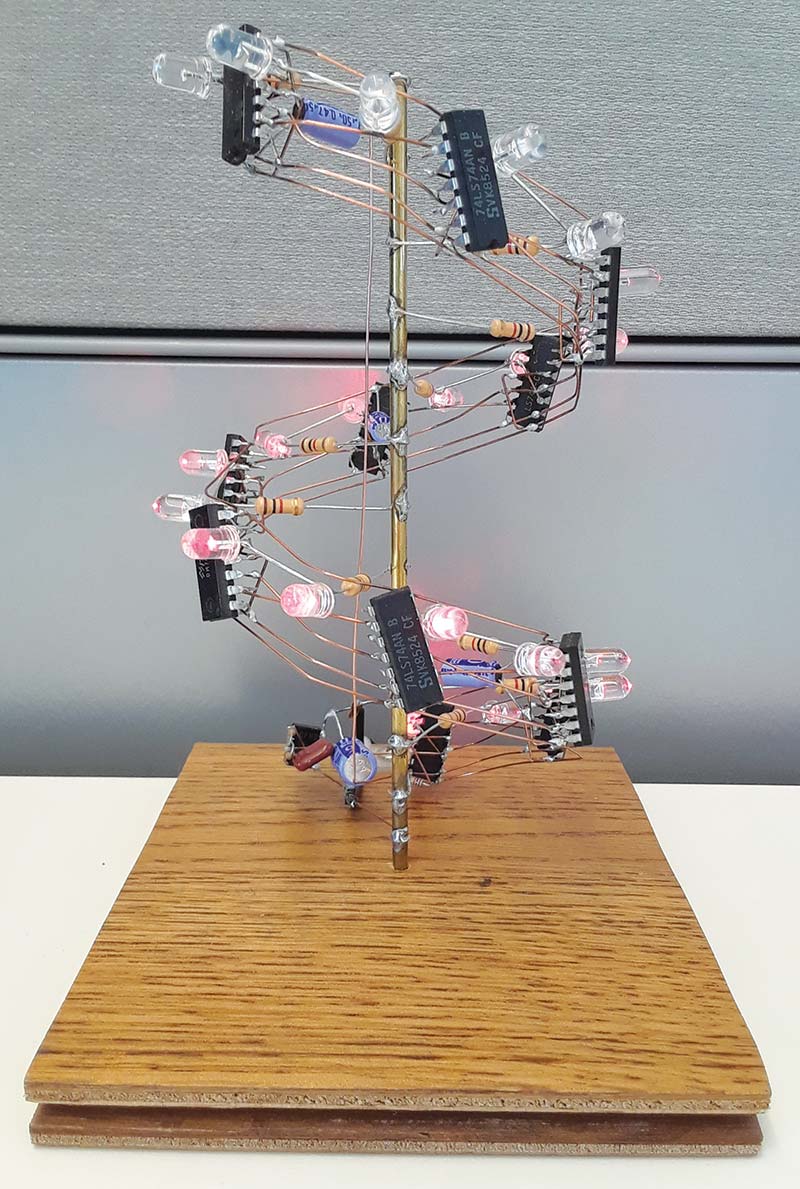
FIGURE 1. Johnson ring counter as a helix.
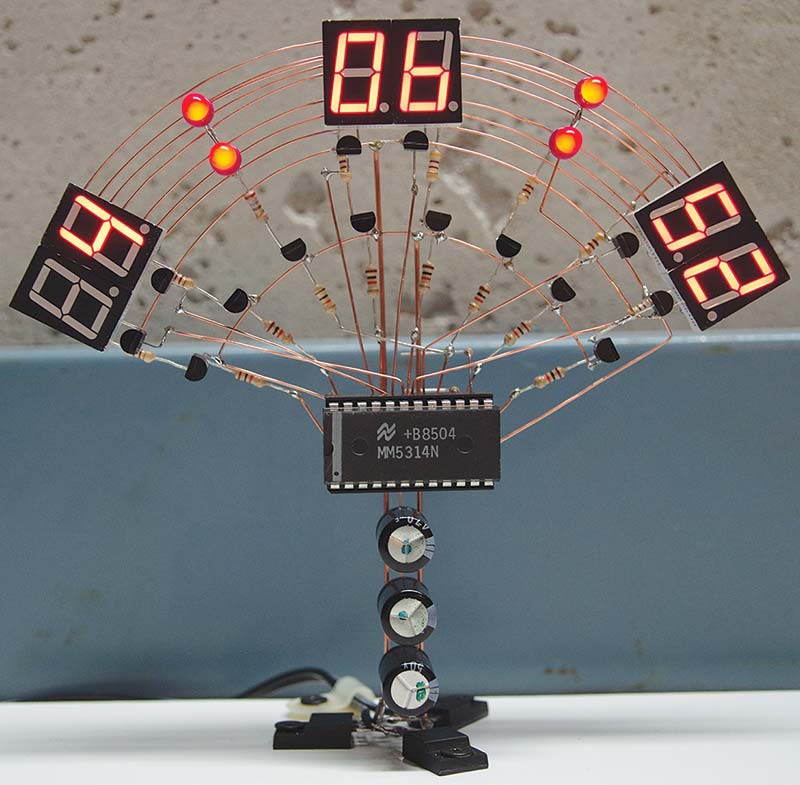
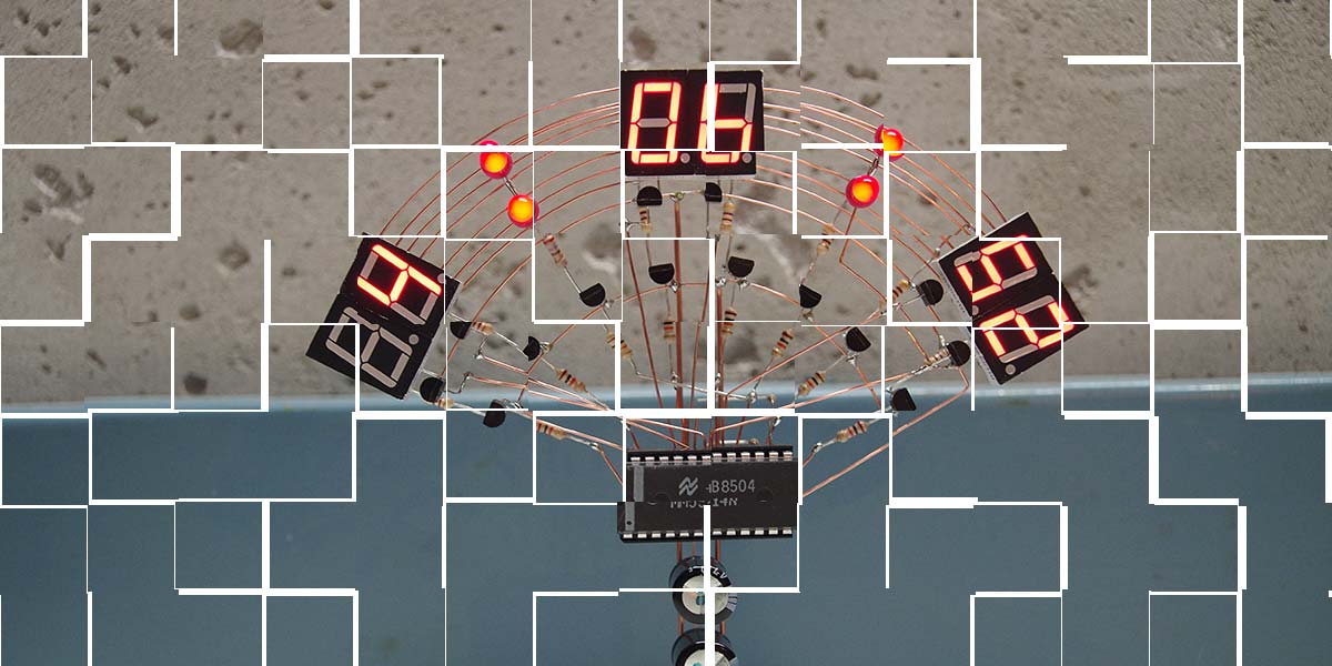
FIGURE 2. Digital clock kit, reimagined.
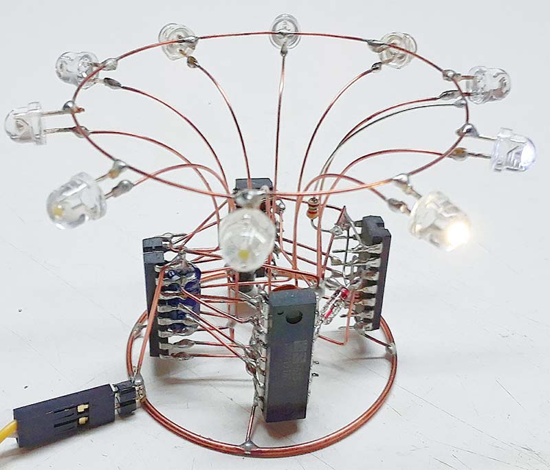
FIGURE 3. “Cylon Eye” LED flasher as a circular beacon.
Designing a circuit using this construction style is more challenging than conventional construction because it requires you to keep constructability and structural integrity in mind from the start. At the same time, it gives you more freedom to play with a circuit’s artistic aspects.
Once you’ve imagined your circuit, a detailed, full-sized construction template is a must (Figure 4) and should be developed in parallel with the circuit schematic. This establishes the orientation and spacing of all the parts, helps you start to visualize where the connecting wires need to go, and makes sure that it is buildable.
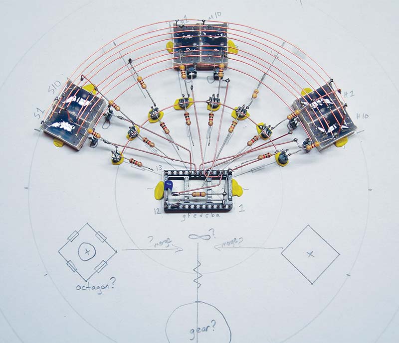
FIGURE 4. Digital clock under construction on its template. Holes in the paper let the Plasti-Tak adhere to the bench surface.
Be prepared for an iterative process where the physical layout requires changes to the schematic, and consider whether the circuit can be built in its final form or should be built and then bent or shaped as needed. For example, the digital clock was built largely in its final form on the template and then mated with its power supply (the supporting “stalk” in Figure 2) which was constructed separately. The ring counter was constructed in one long diagonal line on a graph paper template and then bent into a helix and soldered to the central support post.
The LED flasher used a modular assembly style. Each individual chip became the core of a circuit module, with components soldered to their undersides. The LED ring was assembled on a construction template and then attached to the 74LS42 decoder/driver chip module. The four chip modules were placed on their ends on a second construction template and wired together, and finally the base ring was attached.
This circuit also required some purely structural wiring connections between the 74LS04 inverter chip and the adjacent chips to keep the entire ring-shaped logic circuit physically stable. These wires connect to an unused input on one (or both) of the adjacent chips and have no effect on the circuit operation. I created a separate structural layout diagram (Figure 5) to help plan these connections.
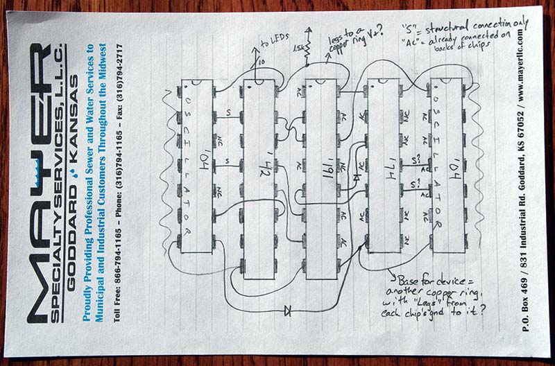
FIGURE 5. Structural layout diagram for the Cylon Eye. Note the structural-only connections.
The schematics for the ring counter, digital clock, and LED flasher circuits are shown in Figures 6, 7, and 8, respectively.
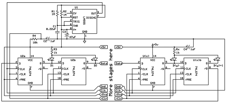
FIGURE 6. Schematic for the Johnson ring counter.
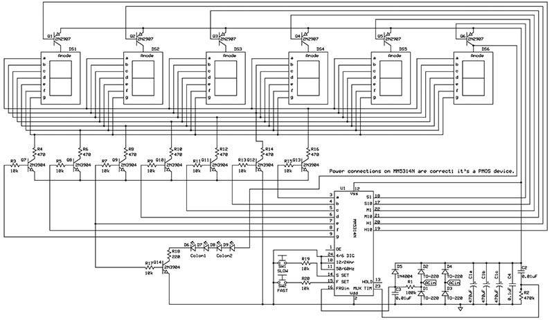
FIGURE 7. Schematic for the digital clock. The blinking colons use the “e” segment signal of the seconds digit.
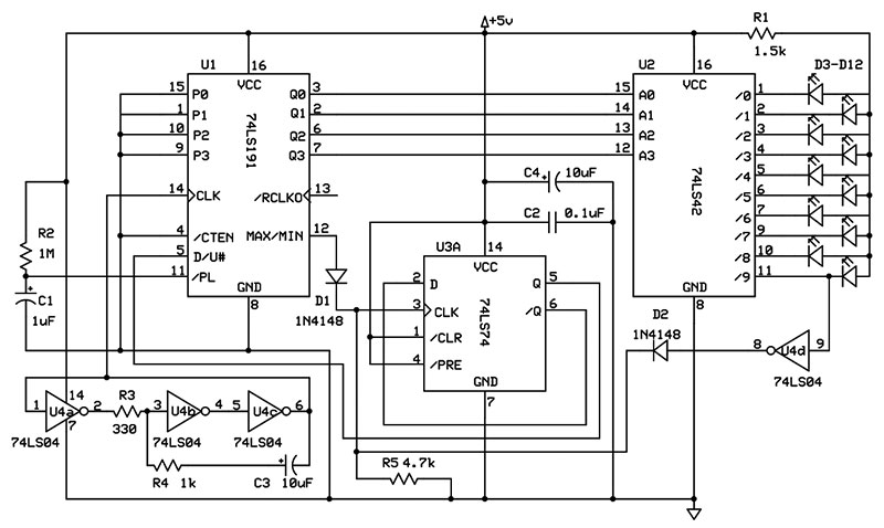
FIGURE 8. Schematic for the LED flasher.
The ring counter can be built to any length; I used 11 74LS74 chips for a total of 22 stages. Just remember to connect the not-Q output of the last stage to the D input of the first one. The /CLR inputs of each stage connect to a simple R-C delay circuit to ensure that all LEDs turn on at startup.
The digital clock circuit is right out of the datasheet for the MM5314 clock chip and uses common-anode displays. The time base signal comes from the 60 Hz power line frequency. I added blinking colons between the hours, minutes, and seconds by tapping into the “e” segment signal for the seconds digit. They only miss one blink cycle every 10 seconds, which is not bad considering no additional logic was required. The fast and slow set switches are simply 10K resistors with their leads bent to within about a millimeter of the five volt bus.
The LED flasher uses a 74LS191 up/down counter to drive a 74LS42 one-of-10 decoder that lights one LED at a time. Half of a 74LS74 flip-flop toggles the up/down input on the counter whenever the count reaches zero or nine, using a diode-OR circuit to get the “zero” signal from the counter and the “nine” signal from the decoder.
The 74LS04 inverter-based oscillator is from the book, Electronic Design with Off-the-Shelf Integrated Circuits. It was published in 1980 and is specifically designed for TTL inverters. Another simple R-C delay circuit resets the counter to zero on startup.
By now, I hope you’re already brainstorming for your next project to build copper cobweb style. Good candidate circuits have a modest parts count and can be built with through-hole parts. A simple off-the-shelf circuit kit can often be built (or re-built) as a cobweb, so you can ditch the boring circuit board that came with it (Figure 9).
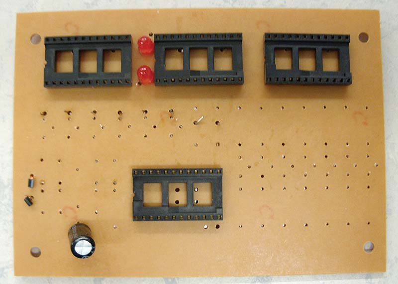
FIGURE 9. The digital clock cobweb used to be a PPG Electronics 776-DC clock kit. Compare this to Figure 2. Quite an upgrade!
Use components that are not particularly static-sensitive so they don’t get damaged during construction or handling. My digital clock violates this rule as the MM5314 clock chip is a PMOS device, but I got around this by using a socket during construction and only installing the chip once it was complete. Circuits with lots of clock signals, tight timing tolerances, or high impedance inputs may operate unpredictably since a cobweb is basically a big antenna with no shielding. Of course, from an artistic perspective, such operation could be considered part of the charm. Some other construction tips:
- When fixing your components to the construction template, you may need to cut small holes in it so the fixative (I used Plasti-Tak) can also stick to the underlying tabletop for extra rigidity.
- Don’t use too much of the fixative! Keep in mind that you need to remove your circuit from the template once it’s built and using too much force during removal will distort or damage your cobweb. Consider placing the fixative on the edges of the components rather than between the component and the template for easier removal.
- If you plan to bend parts of your cobweb during or after assembly, keep all the wires crossing the bend in the same plane or the bend will distort the cobweb. This is why the 74LS74 chips on my ring counter are slightly tilted rather than vertical as I intended.
- Form all your connecting wires precisely before soldering them in place. If you’re using multiple wires of the same shape (such as the curved wires on the digital clock and LED flasher), use a jig to make sure they are all identical. The less mechanical stress you introduce into your cobweb during assembly, the closer it will be to the desired shape after you remove it from the construction template.
- Like their namesakes, copper cobwebs are fragile. Heavy components or parts that need to be manipulated (buttons, knobs, connectors, switches) should be mounted on a solid support before wiring into the cobweb. With some planning, these components can often be used as the base for the cobweb. The power supply diodes for my digital clock are in TO-220 packages that support the entire clock.
- A good “third hand” component holder with fine-tipped grippers is essential to hold each wire in place while soldering.
Have fun exploring all three dimensions of your next circuit! NV
MM5314 Clock Chip Datasheet
search.datasheetcatalog.net/key/MM5314
“Electronic Design with Off-the-Shelf Integrated Circuits,” Z. Meiksin, Parker Publishing Company, 1980. ISBN: 0-13-250282-8.
Parts List for Johnson Ring Counter (Digi-Key part numbers)
| (11) 74LS74 Flip-Flops, 14-DIP |
296-1668-5-ND |
| LM555 Timer, 8-DIP |
LM555CNNS/NOPB-ND |
| (22) T1-3/4 Red LEDs |
516-2483-2-ND |
| 10K ohm Resistor, 1/6 watt |
10KEBK-ND |
| (13) 1K ohm Resistors |
1KQBK-ND |
| (2) 1M ohm Resistors, 1/6 watt |
1.0MEBK-ND |
| 0.22 µF Capacitor |
495-2838-ND |
| 47 µF Electrolytic Capacitors |
493-5361-1-ND |
| (2) 1 µF Capacitors |
493-12811-1-ND |
| Five volt DC Wall Wart |
eBay |
| Bare 22-gauge Copper Wire |
Hardware Store |
| 1/8” Diameter Brass Rod |
Hardware Store |
Parts List for Digital Clock
| MM5314 Clock Chip, 24-DIP |
eBay |
| 24-pin Socket, 0.6” |
AE10001-ND |
| (8) 10K ohm Resistors |
10KQBK-ND |
| (7) 470 ohm Resistors |
470QBK-ND |
| 220 ohm Resistor |
220QBK-ND |
| 470K ohm Resistor |
470KQBK-ND |
| 100K ohm Resistor |
100KQBK-ND |
| (2) 10K ohm Resistors, 1/6 watt |
10KEBK-ND |
| (8) 2N3904 Transistors, TO-92 |
2N3904FS-ND |
| (6) 2N2907 Transistors, TO-92 |
1514-2N2907APBFREE-ND |
| (3) 470 µF Electrolytic Capacitors |
P12400-ND |
| (2) 0.01 µF Capacitors |
BC5213CT-ND |
| 0.1 µF Capacitor |
399-4151-ND |
| (4) T1-3/4 Red LEDs |
516-2483-2-ND |
| (6) Seven-segment Red LED Displays, Common Anode |
754-1678-5-ND |
| (4) Power Supply Diodes, TO-220 |
1655-1003-ND |
| 1N4004 Diode |
1N4004-TPMSCT-ND |
| Nine volt AC Wall Wart |
eBay |
| Bare 22-gauge Copper Wire |
Hardware Store |
| Bare 18-gauge Copper Wire for Support “stalk” |
Hardware Store |
Parts List for “Cylon Eye” LED Flasher
| 74LS42 BCD Decoder, 16-DIP |
296-27985-5-ND |
| 74LS191 Up/Down Counter, 16-DIP |
296-14886-5-ND |
| 74LS74 Flip-Flop, 14-DIP |
296-1668-5-ND |
| 74LS04 Inverter, 14-DIP |
296-1629-5-ND |
| (10) T1-3/4 White LEDs |
365-1177-ND |
| (2) 1N4148 Diodes |
1N4148FSTR-ND |
| (2) 10 µF Electrolytic Capacitors |
493-13313-1-ND |
| 1 µF Electrolytic Capacitor |
493-12811-1-ND |
| 0.1 µF Capacitor |
399-4151-ND |
| 1.5K ohm Resistor, 1/6 watt |
1.5KEBK-ND |
| 1K ohm Resistor, 1/6 watt |
1.0KEBK-ND |
| 4.7K ohm Resistor, 1/6 watt |
4.7KEBK-ND |
| 1M ohm Resistor, 1/6 watt |
1.0MEBK-ND |
| 330 ohm Resistor, 1/6 watt |
330EBK-ND |
| Five volt DC Wall Wart |
eBay |
| Bare 22-gauge Copper Wire |
Hardware Store |
| Bare 18-gauge Copper Wire for Base Ring |
Hardware Store |