We often find ourselves in the position of having worked hard on a project through all the various stages including concept, block diagram, schematic, PCB (printed circuit board) design, PCB manufacture, assembly of the PCB, selection of an enclosure, layout and drilling/machining of the enclosure’s various panels, and installation of the whole shooting match into that enclosure. All that’s left is to test the unit and to apply the various labels and legends to the enclosure. Sometimes though, that last step is the most difficult one of the entire project experience, but it doesn’t have to be!
The problem that I and many other builders have is that there is no one good way to label out your project enclosure, based on the many different material types, colors, and surface finishes to be found out there. This article will discuss some of the methods that I have employed and will point out the pros and cons of each method.
Labeling methods range from the very simple to the fairly complex with the end results generally tracking the methods as regards to finished appearance and functionality.
The methods we’ll discuss are:
- Handwritten Markings
- Taped-on Printed Labels
- P-touch® Labels (or equivalent) – Individual labels for each control, indicator, etc.
- Opaque Label Sheets – Single self-adhesive label to cover an entire panel.
- Translucent Label Sheets – Single self-adhesive label to cover an entire panel.
- Waterslide Decals – Full-panel label or individual labels, or label-on-label.
As can be surmised by the list above, marking options run the gamut from rudimentary to very professional looking. A quality labeling system perfectly complements that top project you worked so hard to perfect, and it’s not much more work.
Handwritten Markings
It’s easy to see how this can be the easiest means of marking an enclosure. Figure 1 shows a black ABS plastic enclosure around a simple 9 VDC to 5 VDC converter.
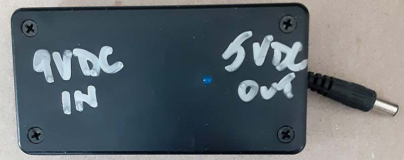
Figure 1. Handwritten markings on black ABS plastic.
This unit was cobbled together in about 10 minutes, and it was meant to be a temporary-use item. I never intended for it to be around for very long.
Thus, I just marked it with a Sharpie® marker — a silver one to show up on the black ABS.
By the way, note the blue LED next to the “5 VDC OUT” marking. I generally use a blue LED as my standard for “Power On” or “Power Good” indicator lamps. I don’t remember why at the time that I built this little unit I felt that I needed the LED indicator, but for some reason I did, and so there it sits.
This method doesn’t work very well for me because my handwriting is terribly sloppy and barely legible to most other folks. In fact, it’s for that very reason that I prefer to complete all forms on a computer, typing the information in so that it can be read by others. (I have this love/hate thing going on with my doctor’s offices. They love me when I bring in forms that I have pre-completed, but hate me when I have to fill in forms on the spot!)
Needless to say, handwritten labels are out for me, but they may work very well for someone else. White, silver, and gold Sharpie markers are readily available at several stationery stores.
Taped-on Printed Labels
From time to time, you may encounter a label that requires some pictorial content rather than just text. Worse than that, maybe your enclosure is the ubiquitous black ABS plastic material, meaning that you need a contrasting background for your label. The solution may be as in Figure 2 and Figure 3.
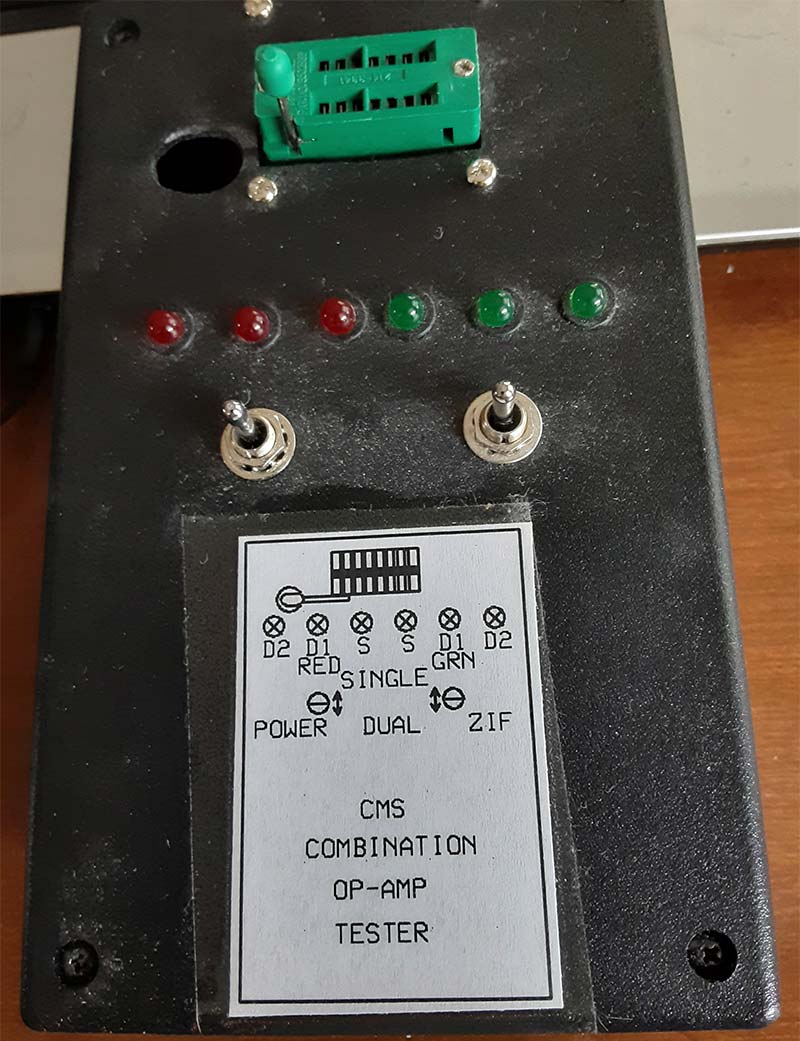
Figure 2. Taped-on printed label with illustration.
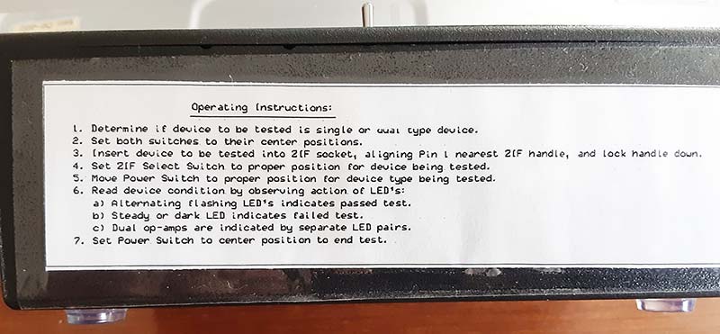
Figure 3. Side view of same unit with printed label of instructions.
Print the markings on plain white paper and then tape those labels onto the enclosure.
Okay. So, this method works, but it’s not very pretty. The tape is a pain to deal with and it’s important to cover the entire label with the tape to protect it from damage like tears, stains, fingerprints, and so forth.
However, it was this method that got me thinking about other ways to achieve this result with less steps and with better appearance.
Did you happen to notice the hole in the top surface of the enclosure shown in Figure 2? The hole is just to the left of the ZIF socket. That hole is there to allow the ZIF socket closure lever to go all the way down.
Because the ZIF socket is mounted to a PCB beneath the top cover of the enclosure, it’s necessary to allow clearance for the handle.
P-touch or Equivalent
Occasionally, the marking needs are very simple; just a single line of text or one or two simple controls. Consider the emergency cell phone charger shown in Figure 4.
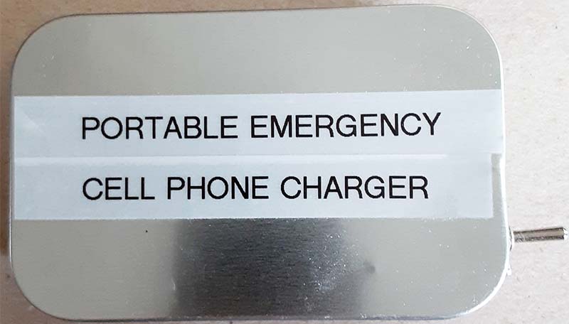
Figure 4. P-touch label on mint tin project.
The only real marking is an identification label and a “1” and “0” at the power switch (not shown).
This unit was built in a mint-sized tin enclosure. I chose to go the P-touch route on this one since it was so simple. Successful, right? Because the needs were so basic and size so small, this marking method was ideal for the project. Not quite so with my next example.
This project was much more complex, and the P-touch methods looks downright silly on this unit. This project was an inductance meter adapter used to measure inductance using a standard multimeter. Refer to Figure 5 and note that the enclosure is not even marked on its face as to what the unit is or does!
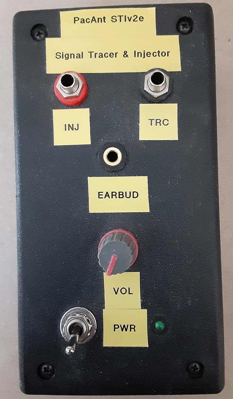
Figure 5. Inductance meter adapter with P-touch labels.
The labels are sloppy; that’s my fault. But even if they were cut with perfectly square corners and were aligned exactly straight and even, the overall effect would still be the same. It looks like exactly what it is — the easy way out of the labeling problem.
Figure 6 shows the side view of the same project where the unit ID is located.
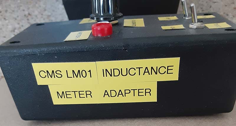
Figure 6. Side view of inductance meter adapter.
Not the best approach to this issue, but it did lead me to seek out a better way. And remember, we’re still working with that blasted black ABS!
Opaque Label Sheets
One day, I got to searching the Internet for the next better idea. I had decided that I wanted to be able to print a self-adhesive label for each of the various panels of a project on which I wanted to place markings. Because of the black material color and because I was going to run it through my color laser printer, I needed a light colored label. I decided that white was as good an any other light color for my purposes. You may decide that you want a pale blue, pale yellow, or a pale green, and so forth. That’s entirely up to you.
I found letter-sized (8.5” x 11.0”) label sheets readily available on the Internet from a variety of sources including www.amazon.com and www.onlinelabels.com. I found both paper and lightweight vinyl or acetate labels, both of which I’ve used. With your favorite drawing program (I use CorelDraw) and some accurate measurements, it’s possible to create a label that will fit your enclosure’s panel and have text markings for each control and indicator. You can include a logo if desired, as well as an equipment ID label.
Figure 7 shows one such implementation of the white label concept.
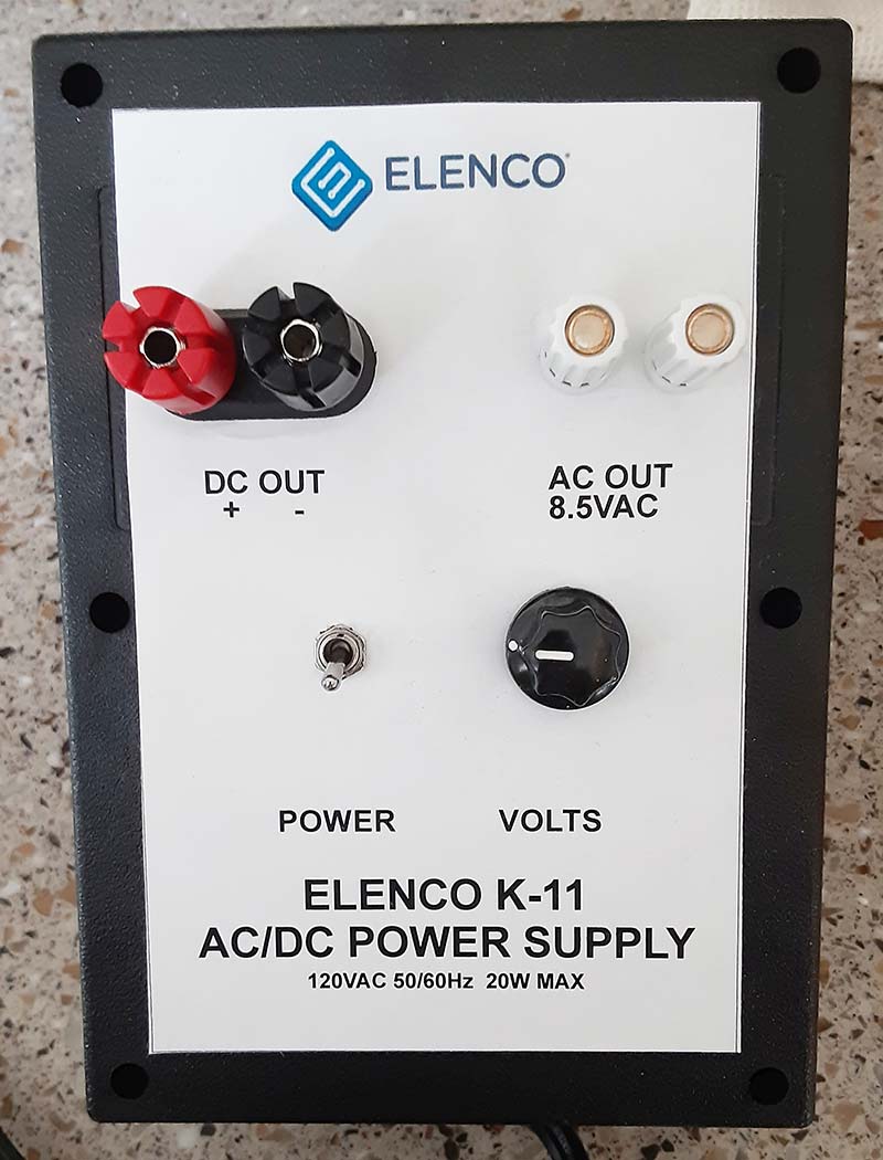
Figure 7. Opaque sheet label on power supply.
This was rather poorly implemented, as we (my grandson and I) left too much white space above some of the markings. However, note that this label includes the board manufacturer’s name and logo.
This was an open-board project as supplied by Elenco. We obtained a suitable enclosure and moved the works into that enclosure. This one looks much better than the project in Figure 5. We’re getting there!
Translucent Label Sheets
The next stop on this journey was to move to see-through label sheets. These too were easily obtained online from the same sources. The capacitance decade box in Figure 8.
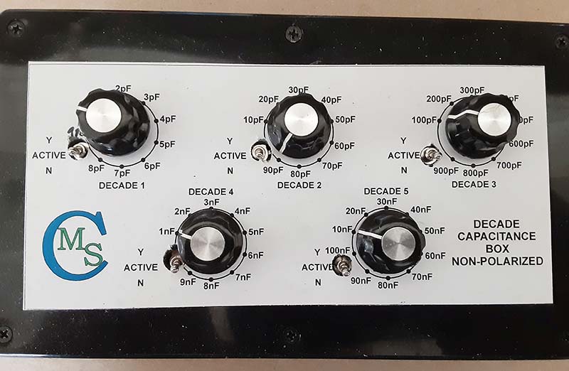
Figure 8. Opaque sheet label on capacitance decade box.
The resistance decade box in Figure 9.
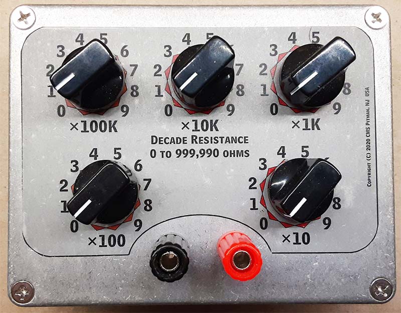
Figure 9. Translucent sheet label on resistance decade box.
The DDS signal generator in Figure 10 are all examples of the translucent label sheet method employed on projects.
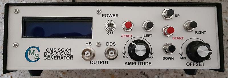
Figure 10. Translucent label on DDS signal generator.
Each of these project labels had its own problems. Look closely at Figure 8 and you’ll see that the layout of the decade selector switch for the fourth decade (lower left) is out of place and that the panel hole had to be enlarged to accommodate the switch. In this case, the switches — both rotary and toggle — are mounted to the PCB and are thus in a fixed location. Though the hole placement was transferred to the enclosure cover by marking through the bare PCB, the hole somehow ended up misplaced.
The resistance decade box in Figure 9 came out better, but the label is slightly under scale meaning that the label hole locations did not align perfectly with the holes in the enclosure cover. We’ll discuss scaling later on, but it’s something of which you must be aware as it can make all the difference in the final appearance of your project.
Now look at Figure 10. This label is the most ambitious label that we’ve seen so far. The DDS signal generator has multiple controls, two BNC jacks, and an LCD panel. All of these must be positioned to fit properly in the enclosure, and then the label must be made to line up with all of the opening placements. There are a couple of ways to do this. I’m going to talk about one method that I believe gives the best results.
Start out in your drawing program by creating the label, first drawing an outline that represents the overall label dimensions and then placing each and every opening in its precise and measured location and size within that label outline. If you have the components on hand, you can measure them with a dial caliper to get the precise diameters of the various holes.
In some cases, such as when laying out the LCD opening, the component datasheet will help you by providing exact and detailed dimensions for the openings.
For each of the round openings, place a circle the exact size of the finished hole to be made in the panel. Next, I like to place a 0.010” filled circle at the exact center of each of the circles already drawn. These 0.010” “dots” become my center punch reference marks in preparation for drilling. Keep your line widths as fine as your software allows. They are guides, but they’re not to be seen in the finished product.
Next, place the text markings for each of the controls, indicators, and jacks. Be sure to allow space around each switch, control, jack, indicator, and so forth for the mounting hardware and for any control knobs. You don’t want your text to be covered by a control nut or by a knob.
Now place any other information such as directional arrows, etc. Finally, place any other information that you want on your label, such as the equipment name and your logo.
Look carefully at Figure 10 and you’ll see that the legend for the power switch is partially covered by the switch hardware. This is an example of what not to do! The mark in the reset legend happened during use of the signal generator, though I don’t recall exactly how it happened.
Okay, the label is prepared. Make sure you save the file and then print a proof copy of the label on plain paper. Check the proof copy carefully for typographical errors, and then cut it out along the label outline. Lay it in place on the enclosure and make sure that everything will work as you designed it. Pay special attention around the edges, making sure you have the requisite clearance to the enclosure body.
Check the proof copy for size. If your label was designed to be 9.5” x 2.8”, measure the printed label and make sure that it’s the correct size. If it’s not, you’ll need to correct the printer scaling and reprint the proof to check it again. You may need to repeat these steps a couple of times to get it exactly right, but it will be worth it in the end. We’ll discuss scaling later on in this article.
If everything checks out okay on the proof, go ahead and set up the label stock in your printer and print the label. Cut it out carefully. Next, install it to the enclosure panel, being careful to position it exactly straight and where you want it to be. Once the label is in place, you can center punch the holes and drill them through the label.
I cut large round or rectangular openings using a “nipper” tool, available online from many sources. Do a web search for “nipper” or “sheet metal nipper” to find one. Using the nipper generally requires the drilling of a 3/8” or 1/2” hole through which to get started, for which I generally use a stepped drill bit.
The techniques described above will work equally well with the opaque sheet labels, though some care must be taken when drilling through the acetate or vinyl sheets. I generally cut along the hole outline with the pointed tip of a hobby knife prior to drilling so that the sheet will not pull or tear at the drilling location.
Of course, the translucent sheet labels will only work with light-colored enclosure surfaces, but one of my favorite enclosure designs is a two-piece black-over-white aluminum enclosure such as that used for the signal generator shown in Figure 10.
Waterslide Decals
Still looking to improve on my labels and markings, I hit upon the idea of using waterslide decals. These are the same types of decals that we used to put on plastic model cars, ships, and airplanes that we built as kids. Waterslide decal stock is also readily available on the Internet. I purchased mine, of course, from Amazon.
While it isn’t exactly cheap, it’s also not so expensive that the average builder can’t afford it. It’s well worth the cost when it comes to the finished project appearance.
Look at the enclosure shown in Figures 11 through 13.
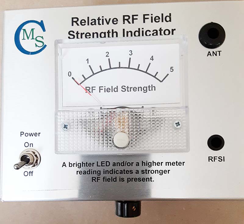
Figure 11. Waterslide decal on RF meter front with custom label on meter face.
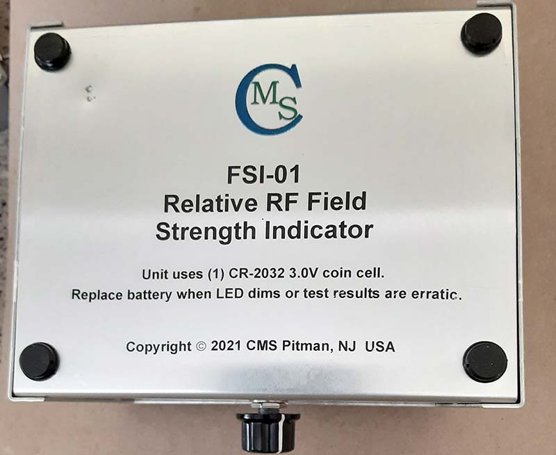
Figure 12. Waterslide decal on RF meter back .
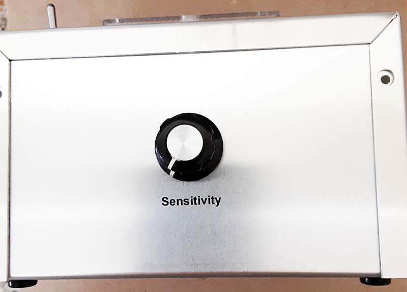
Figure 13. Waterslide decal for single control on RF meter body.
They depict an enclosure for a relative RF field strength indicator that I just completed. Figure 11 shows the business side of the project. Note that the meter — a 0-50 mA meter — has had a replacement face label installed. That was done by first removing the factory scale plate from the meter and scanning it into CorelDraw.
This scan was then used as a drawing template from which to create a new scale. I drew a large circle whose circumference matched the arc in the meter scale.
Next, I added diameter lines at various angles that would become the scale “ticks” when trimmed. Using concentric circles, I trimmed the ticks to two different lengths for the whole and half units. I then cut the original circle to an arc over the original in the photo and increased its line weight to approximate the original arc. The tick marks were all now in place with their lower ends embedded in the arc.
I added the textual numerals over the scale and the text below the scale. After printing the new meter face on plain white self-adhesive label stock, I cut it out and placed it on the back of the original metal meter face, which was then re-installed into the meter. Installation of the meter crystal completed the job.
This project required two panel-sized decals and a small text label one. I printed them all on a single sheet of decal stock, placing the text label in the gap between the two panel-sized labels. All three decals were installed onto the blank enclosure before any holes were drilled or cut.
Because the decals will slide around until the water is squeezed out from behind them, precision alignment is relatively easy to accomplish. Handling the decals does take a little bit of practice, but the practice pays huge dividends as you can see in the end result.
If you want to add long-lasting protection to your decal labels, they can be covered when thoroughly dry with two light coats of KRYLON® or RUST-OLEUM® clear matte or semi-gloss spray, allowing the finish to dry completely between coats.
You may also find it easer to position the decals on some aluminum surfaces if you prepare the surface with one or two light coats of the same clear spray finish before applying the decals.
When applying the decals, take care not to allow the edges to fold under, as it’s extremely difficult to “unfold” them once this happens. Once the decals are completely dry (as well as any spray finish you may have applied), the drilling and cutting can begin.
These labels are prepared the same way in the drawing software, so you’ll have your drill guide circles and center punch points in place already. Cut the large openings the same way, using your nipper and cutting along the opening guidelines. Smooth the edges of the opening with a fine file if necessary.
Waterslide Decals
Waterslide decals are called this because of their method of application.These decals are printed onto an acetate film that is mounted to a paper backing or carrier sheet. Soaking the printed decal in lukewarm water for several seconds will allow the decal to become loosened from its carrier, making it possible to slide the decal off the backer and onto its target substrate.
The decal is readily moved around on most surfaces until the bulk of the water is squeezed out from behind the decal, which is best done with a soft paper towel or facial tissue, working from the center out towards the edges of large decals.
Because of the means of application of these decals, it’s important NOT to print them with water-soluble inks. Waterslide decal stock is available for both ink-jet and laser printers in standard printer paper sizes.
To apply the waterslide decals, momentarily immerse the decal on its backer in a dish of lukewarm water into which a drop of dish soap has been added to break the surface tension. I find it best to gently hold the decal on its opposite edges with my fingers while I dip it in the water for a second or two. I repeat the dipping sequence two (or maybe even three) times as needed to free up the decal from its backer sheet.
With the decal still on its backer sheet, place it on the surface of the enclosure where it will ultimately remain, and slide it gently about a quarter or three-eighths of an inch off to one side. Then, hold the exposed portion of the decal with one or two fingers while you slide the backer sheet out in the opposite direction, allowing the decal to settle onto the enclosure surface.
Position the decal where you want it to be, and then gently wipe the water out using a soft paper towel or some facial tissues. Working from the center out to the edges, wipe gently until all the water is out and the decal is nice and smooth with no wrinkles or smudged areas. Set the enclosure aside and allow it to dry thoroughly, which can take an hour or more.
The heat of a light bulb (not a heat lamp) or a blow-drier set on low temperature and speed can help speed the process. Too much heat applied too quickly can shrink and shrivel the decal, though, so I prefer to allow it to air dry. I’ve got plenty of other work to do on the project. I planned it that way!
Decal stock is available in both clear (transparent) and white material, so it can be used on those black ABS enclosures if you print on the white stock. The decal stock, as well as all the other label stock discussed in this article, is available in multiple different sizes, most notably US letter and metric A4 sizes.
Verify the size and make sure it’s what you want before you click the “purchase” button.
Printer Scaling
Earlier, I said that we would discuss printer scaling. This topic, though it can be dry and boring, is an absolute necessity in being able to print proper labels for your project. There is really no sense in taking precise measurements and then placing objects precisely where we want them only to print a label where nothing lines up properly. The most common cause of labels not matching the enclosure properly is printer scaling!
Whether you’re aware of this or not, most every printer and most drawing applications have the ability to change the size or scale of the printed output. In our drawing software, we want everything to be scaled 1:1 or at 100% of its design size. Thus, a 1/4” hole will actually be one-quarter of an inch in diameter, or a 2.125” x 0.95” rectangular opening will actually be 2.25” x 0.95” in its finished size.
However, despite its best intentions, your printer may not faithfully reproduce those dimensions. In this section of the article, I’ll explain how to correct this if it happens.
Start out by printing your label drawing on plain paper. Before pushing the PRINT button in the software print dialog, make sure that the print output scaling is set to 1:1 or 100%, whichever method is used by your software. Then, carefully measure the overall dimensions of the printed label.
If the label size in the drawing software was specified as being 9.5” x 2.9”, then that is what we’re hoping to find when we measure the printed label. If the label is not that exact size, you’ll need to adjust your printer scaling setting. So, how is this done?
In most cases, it’s pretty simple. Explore your printer properties dialog and look for the section labeled Printer Scaling. Make sure that the scaling feature is set to 100% or to 1:1, whichever method is used. If the setting was NOT set at 100% or its equivalent, set it and reprint the label.
Measure the printed label and see if it came out at the specified size (9.5” x 2.9” in our example). If it measures correctly, all is well, and you can move on with fitting the proof and then printing the final label.
If, however, your reprinted label does NOT measure 9.5” x 2.9”, you’ll need to determine the correct scale factor to apply to get your printer to print what you need. Suppose your label measures 10.0” x 3.05”. What scale factor would we need?
The formula needed is SPEC / ACTUAL = SCALE. In this case, the spec is 9.5” and the actual is 10.0”. That gives us 9.5/10.0 = scale, or 9.5/10.0 = 0.95. Thus, we would set the printer scale setting to 95%; 10.0 x 0.95 = 9.50, or exactly what you’re looking for.
So, what happens if the original printed template is smaller than specified? Again, it’s easy, and the formula is the same. Suppose your print came out as 9.25” x 2.82”… 9.5/9.25 = 1.027. Thus, we would set the printer scale setting to 100.03% ... 9.25 x 1.03 = 9.5275, or 9.5” for our purposes here.
For my network, the default printer is a Brother HL-3170CDW. Figure 14 depicts the Advanced tab of the Printer Properties Sheet for that printer.
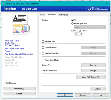
Figure 14. Printer scaling dialog.
It shows that the scaling feature is turned off, but that it can easily be set to scale the print output to a specific paper size (in this case, letter size is shown) or to any free setting between 25% and 400%. Your printer’s properties dialog should have a similar setting.
You may have to explore the various property sheet tabs to locate the setting, but you should find it there somewhere.
That’s a Wrap
I hope that I’ve given you something to think about when it comes to applying markings to your projects. Following the basic guidelines presented here will help you to achieve professional-looking results on your homebrew projects.
Feel free to reach out to me at [email protected] with any questions that you may have on the contents of this article. Happy labeling! NV