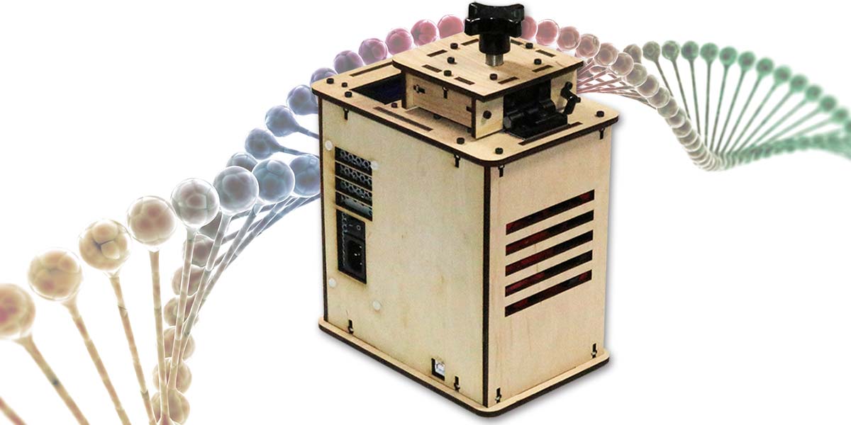
In this DIY Biotech article, we’ll look at an Open Source Polymerase Chain Reaction (PCR) Thermocycler kit. (Photo 1 above) In addition to learning about DNA amplification, we’ll cover thermal sensing, thermal resistance, the thermoelectric effect, and PID controllers.
INTRODUCTION
There are many parallels between the processes used in biotech and those used in everyday electronics. Take amplification. Electrical signals are often too minute to use directly and need to be amplified before being sent to a transmitter antenna, headphones, or speaker. Similarly, if there are only a few strands of DNA on an object — say, a partial fingerprint at a crime scene or a bit of tissue recovered from a frozen woolly mammoth — then it’s often impossible to fully analyze the DNA without amplifying the few strands into several billion strands.
In biotech, this amplification doesn’t rely on tubes or transistors, but on the polymerase chain reaction (PCR): a relatively recent scientific discovery that involves repeated cycles of heating and cooling for specific periods.
THE SCIENCE
Key STEM Concepts
- DNA is a double-stranded molecule that contains an organism’s unique genetic code.
- In DNA, the nucleotide base Adenine binds with Thymine and Cytosine binds with Guanine.
- The PCR is possible because of the heat tolerant Taq polymerase enzyme discovered in E. coli bacteria growing in a hot geyser.
- Thermal cycling — alternative heating and cooling — is the basis for PCR.
PCR and Thermocycling
In addition to thermocycling, the PCR process requires five “wet” components:
- The most obvious component is the DNA to be copied. At least a strand of an organism’s double-stranded Deoxyribonucleic acid (DNA) must be present.
- A soup of the raw materials used to construct DNA — known as DNA nucleotide bases — must be created. These four bases are (A)denine, (T)hymine, (C)ytosine, and (G)uanine. In constructing the double helix of DNA, the base pairings are A-T and C-G.
- Primers that bracket the DNA to be copied. These short pieces of DNA initiate the PCR reaction.
- The heat tolerant Taq polymerase builds the complementary strings of DNA.
- A chemical buffer that creates the optimum conditions for the Taq polymerase to operate rapidly and efficiently. The buffer commonly consists of TRIS hydrochloride (HCl), potassium chloride (KCl), and magnesium chloride (MgCl2).
Given these five ingredients or components, the thermocycling process can proceed as shown in Figure 1. The double-stranded DNA (A) is heated to the point that it denatures or separates into two separate strands (B). The temperature is lowered rapidly in an annealing process that allows the primers to bind to the separate strands, bracketing the segments of DNA to be replicated (C). The temperature is then raised moderately, enabling Taq polymerase to extend or build the complementary strands (D) and release them into the soup. The denaturing, annealing, and extending sequence is repeated dozens of times.
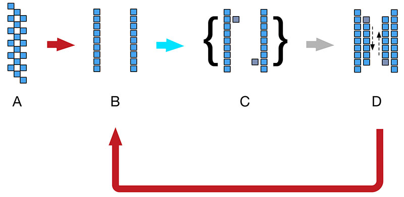
Figure 1. DNA amplification process.
With each iteration, there are twice as many DNA strands as before, or 2N strands, where “N” is the number of cycles. For example, after only 12 cycles, there are 212 or 4,096 strands of DNA. After 20 cycles, there are 220 or 1,048,600 strands, assuming 100% accuracy, which is never actually the case. Even so, we’re talking millions to billions of copies per PCR run. That’s quite an amplification factor.
The rate-limiting step is often the hardware used to rapidly and precisely heat and cool the soup of ingredients. However, even the very simple OpenPCR kit discussed here can run dozens of cycles within a few hours.
THERMOCYCLER DESIGN
The thermocycle kit reviewed here is fully open source. You can opt to buy the kit from OpenPCR for $499 or build it yourself. If you go to the website, you’ll find a complete bill of materials (BOM) including sources, the design of the housing panels in SolidWorks 3D, the PCB (printed circuit board) in Eagle, as well as the source for the software, including the Arduino Uno software. A copy of the BOM is available with this article’s downloads.
An advantage of a truly open source device such as the OpenPCR is that you can selectively upgrade components of the kit. For example, I’m considering substituting aluminum panels for the wooden panels. It would make for a much sturdier device, but at a cost. Another advantage is increased longevity of the system. For example, if the Arduino Uno is discontinued and replaced with a less expensive/higher performance device, you have access to the source code to make any necessary changes.
The major design elements of the OpenPCR device are a PID controller, a Peltier thermoelectric effect device, thermal sensors, and an overall low thermal resistance design.
PID Controller
At the heart of the OpenPCR is an Arduino-based Proportional Integral Derivative (PID) controlled ST VNH3SP30 H-bridge that drives a 25W resistance heater and an 84W heater/cooler Peltier device. The H-bridge is obviously needed, given the current driving capability of a bare Uno is limited to a few milliamps per port. The source code for the PID controller is freely available in the file called pid.cpp. (The full source code can be obtained at https://github.com/jperfetto/OpenPCR. For the pid.cpp file specifically, go to https://github.com/jperfetto/OpenPCR/blob/master/arduino/openpcr/pid.cpp.)
The main components of the code are shown in Listing 1. As you can see, it’s a real PID controller and not — as is often the case — a P or PD controller. All three terms are calculated and used.
double pTerm = error;
double iTerm = iIntegrator + error;
double dTerm = error - iPreviousError;
double output = (pPIDTuning->kP * pTerm) + (pPIDTuning->kI * iTerm) + (pPIDTuning->kD * dTerm);
Listing 1. Basic Proportional Integral Derivative (PID) calculation from the file pid.cpp.
The proportional component of the PID controller produces an error term that is proportional to the difference between a set point or desired temperature and the actual temperature. Purely proportional controls can result in temperatures that oscillate about the set point.
The addition of an integral term addresses the instability of a purely proportional control scheme by the addition of a term that represents the sum of the difference between desired and actual temperature over time.
Even so, a PI controller can result in temperature instability. The ultimate controller then adds a derivative component that limits the second to variation in temperature.
Peltier Thermoelectric Effect Device
The “fun” component in the kit is a formidable 84W Peltier device which has a maximum current draw of 7.8A. Depending on whether it’s forward or backward biased, the unit can heat or cool the tubes containing the PCR soup. The thermal capabilities of the Peltier device are largely a function of the large Cooler Master Hyper 101i CPU cooler which has an integrated fan.
Thermal Sensors
There are two thermal sensors in this kit: one is an integrated thermistor in the heater strip in the cover of the device; and one is a 10K thermistor embedded in the tube holder. (Refer to the BOM available with the downloads for details.) In general, however, both thermistors exhibit a decrease in resistance with increased temperature.
This decrease is measured by the Uno and used to adjust the PID controller, as well as the LCD display.
Low Thermal Resistance Design
A characteristic of this and any other efficient thermocycler is low thermal resistance between the heating and cooling elements and the outside environment.
For example, the Peltier device doesn’t connect directly with the Cooler Master CPU cooler identified earlier, but uses Laird Technologies flexible graphite pads as well as thermal grease to decrease thermal resistance. A lower resistance translates to a quicker response and potentially shorter cycle times.
THE BUILD
Thanks to a simple design and excellent build documentation, the kit is suitable for anyone who can use a screwdriver and hex wrench. There is no soldering involved. The kit and the build are modular. As shown in Photo 2, there are six modules including the power supply. In all, I spent about four hours on the kit.
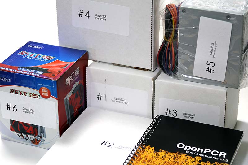
Photo 2. The kit ships in separate modules.
After reviewing the manual, my first step was to remove the paper tape from one side of the laser cut wooden panels (Photo 3).
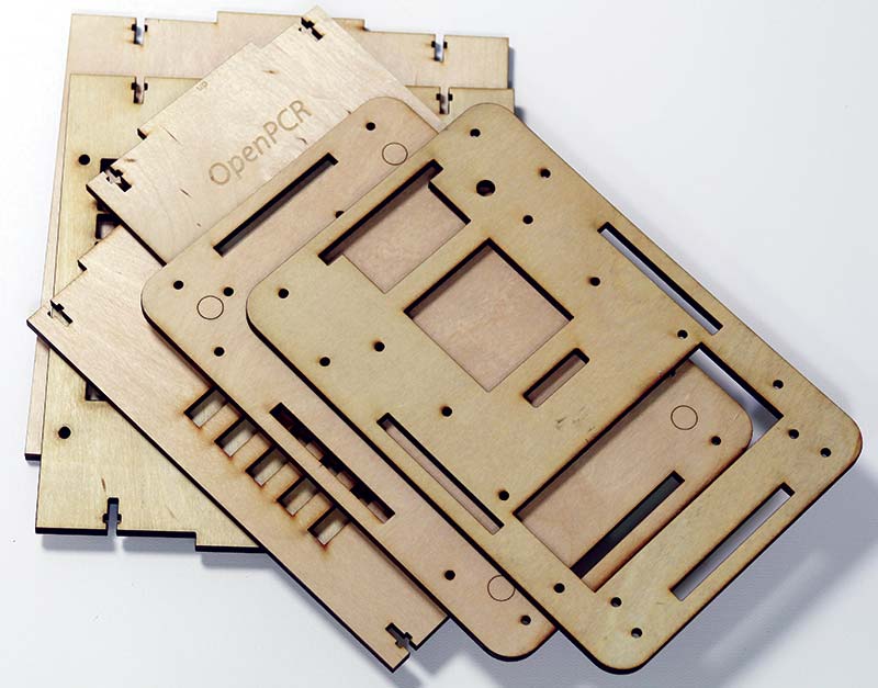
Photo 3. Laser cutouts with tape removed.
The cutouts are sharp, well finished, and the tolerances are tight. Tackling the lid module next, I laid out the small wooden cutouts, aluminum plates, and the electronics (Photo 4).
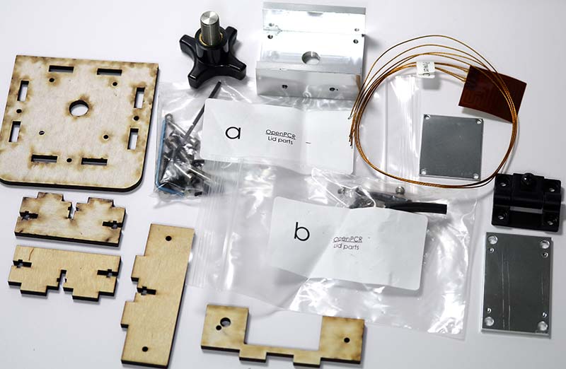
Photo 4. Lid components.
After removing the tape from the small wooden cutouts, I assembled the lid (Photo 5) using the supplied nuts and bolts. Although not part of the kit, I used red Loctite on the nuts and bolts.
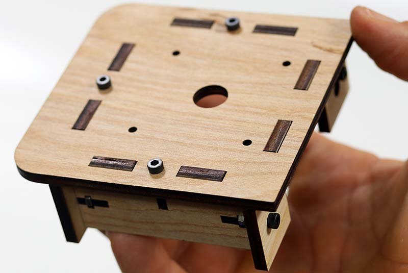
Photo 5. Lid panels assembled.
Next, I attached the Kapton 25W/11.3V heater/sensor assembly to the aluminum thermal plate (Photo 6). This heater is intended to heat the tops of the microcentrifuge tubes. Because the leads to the heater and sensor are easily mixed up during the build process, it’s a good idea to mark one of the pairs now. I dipped the insulation of the heater leads into red enamel paint to avoid problems later.
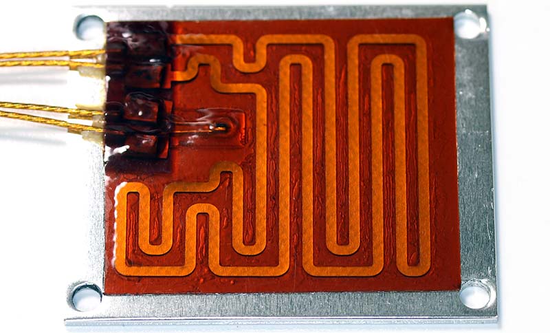
Photo 6. Lid heater/sensor on thermal plate.
If you mix up the leads, you’ll fry the small thermistor and will have to start over with new components. Photo 7 shows the assembled lid from the bottom. The heater/sensor element is just behind the aluminum plate in the photo.
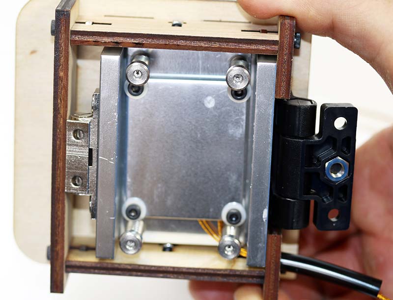
Photo 7. Assembled lid from bottom.
Next, I opened the tube heater/cooler box and noted the 85W Peltier device, the aluminum tube holder, and mounting hardware (Photo 8).
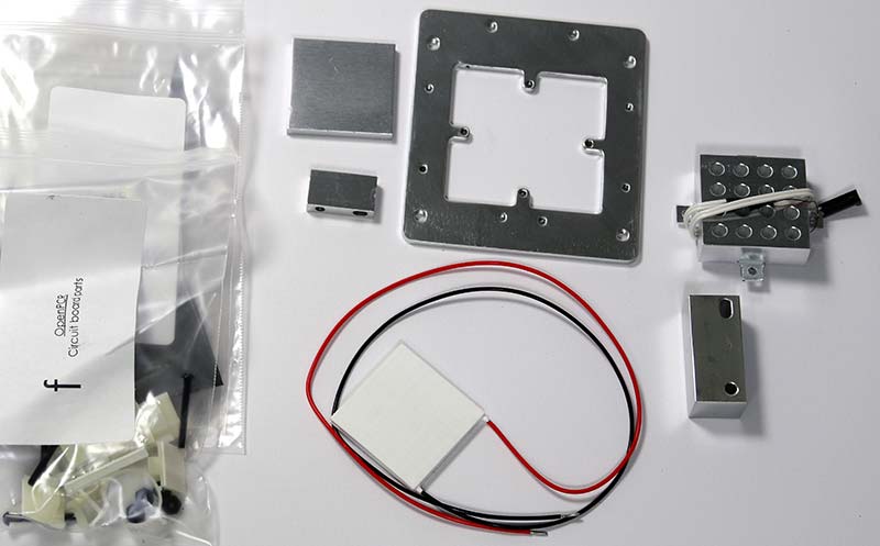
Photo 8. Tube heater/cooler parts.
Photo 9 shows the Peltier device which makes contact with the aluminum tube holder on one side and the large heatsink on the other through thin graphite sheets.
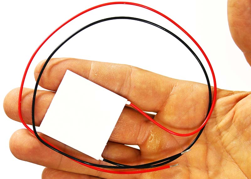
Photo 9. Peltier device.
Photo 10 shows the aluminum tube holder along with a very delicate wire to the thermistor mounted in the tube holder.
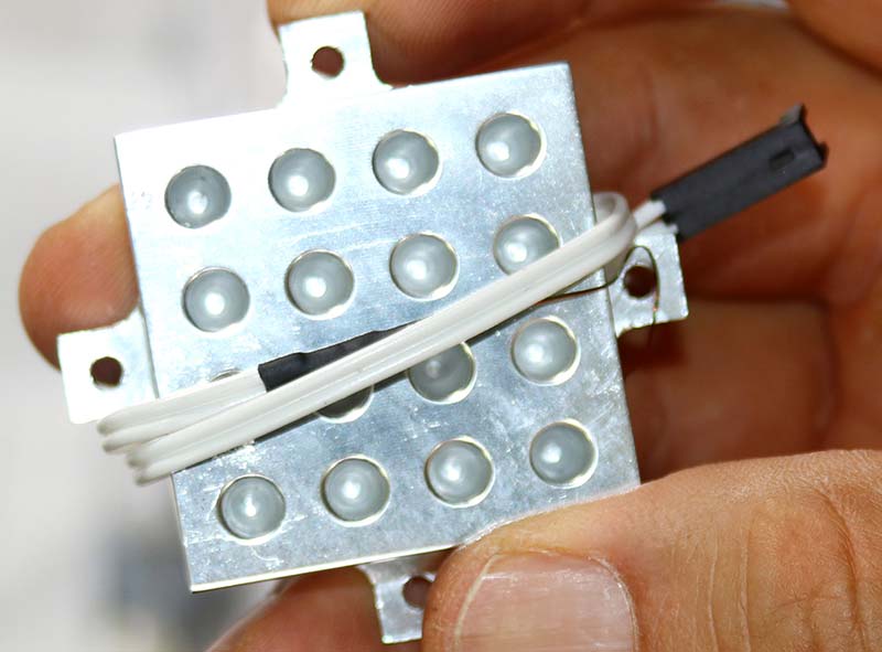
Photo 10. Tube holder/temperature sensor.
Photo 11 shows the cooling assembly including the external fan before I mounted the aluminum plate to the underside of the unit.
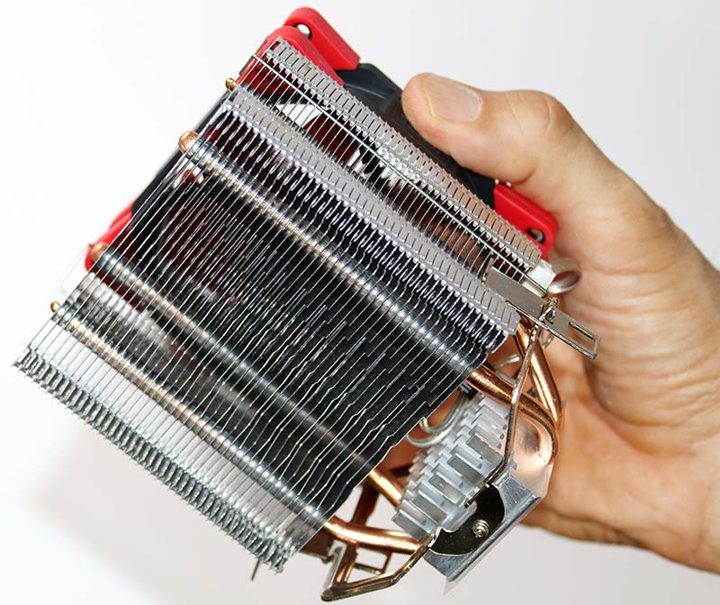
Photo 11. Cooling assembly for Peltier device.
Photo 12 shows the underside of the cooling assembly with the Peltier/tube holder held together by four screws.
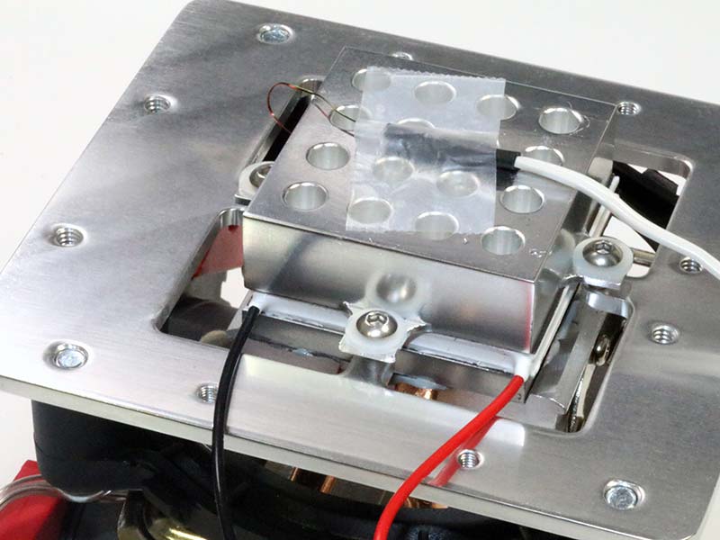
Photo 12. Peltier/tube holder stack.
Be careful not to over-tighten these screws because the aluminum tabs will bend, shifting the alignment of the stack. In assembling the stack, I applied thermal grease directly to the copper and aluminum parts of the heatsink.
With the main heating/cooling hardware mounted, the next step was to install the control and display electronics. As you can see in Photo 13, the electronics consist of an Arduino Uno, a custom controller board to handle the high current heaters, an LCD, and a flat cable.
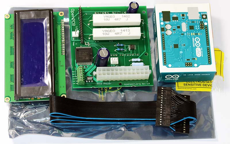
Photo 13. Control and display electronics.
I mounted the Peltier assembly and LCD to the front panel as in Photo 14. Note the orientation of the flat cable attached to the LCD, with the blue wire corresponding to pin 1.
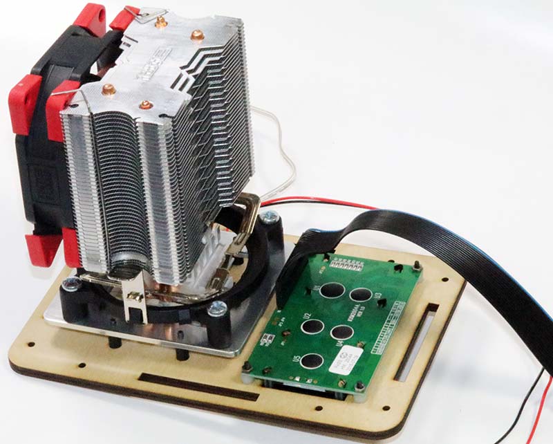
Photo 14. Peltier assembly and LCD mounted to front panel.
Next, I mounted the controller board (Photo 15) and 12 VDC at 14A Micro ATX power supply to the base of the unit as shown in Photo 16.
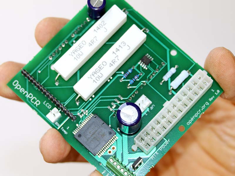
Photo 15. Controller board.
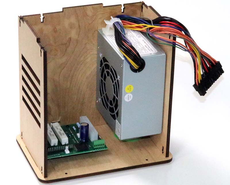
Photo 16. Controller board and power supply mounted in case.
The only steps remaining were to mount the lid (Photo 17) and connect the heaters and thermistors to the custom controller board. I plugged in the unit, turned on the power, and the LCD displayed a ready message.
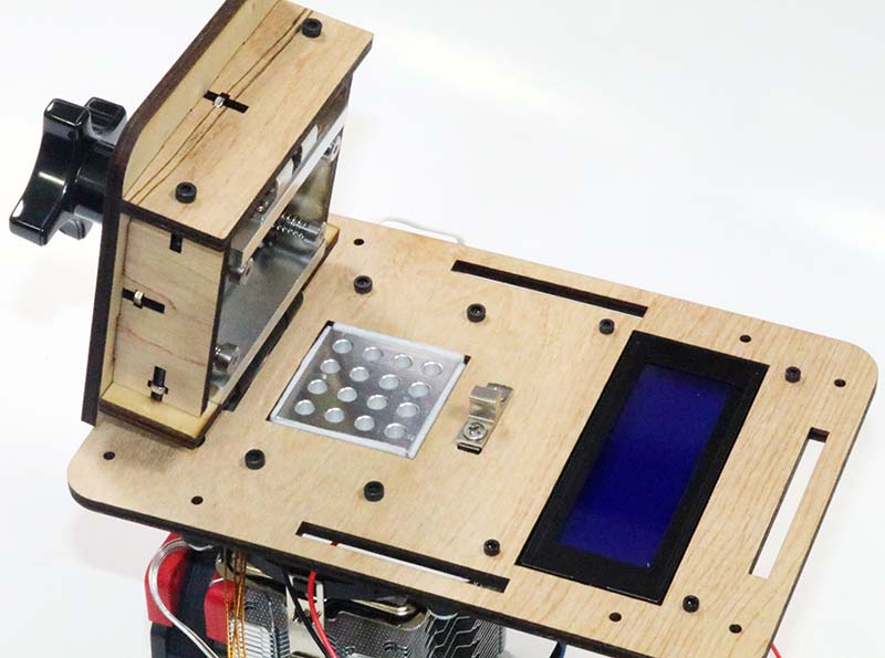
Photo 17. Lid mounted.
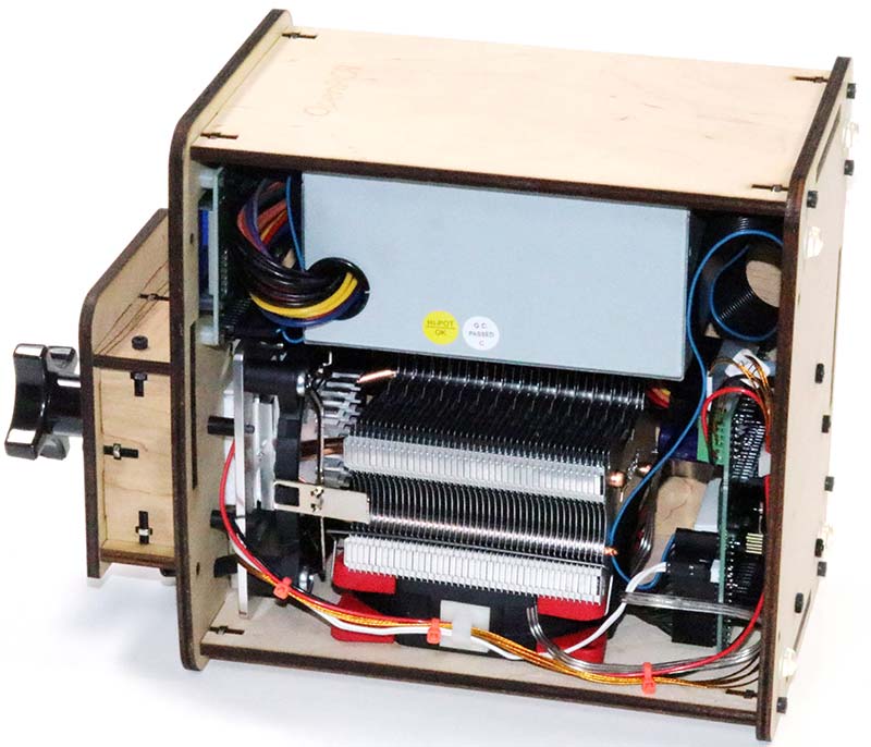
Photo 18. Wired unit.
DRY RUN
To test the operation of the thermocycler, I set up a dry run — that is, without test tubes filled with a DNA soup — using the parameters shown in Figure 2. The denaturing temperature is 95°C, annealing temperature is 55°C and the extending temperature is 72°C.
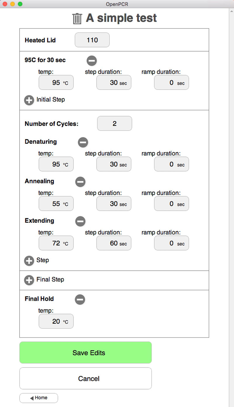
Figure 2. Mac/PC user interface.
Photo 19 shows step 10 of the thermocycler when the tube temperature is 55.0°C and the lid is 109°C. The display is updated in real time with the current temperature and step. According to the LCD display, the thermocycler tracked the planned temperature and duration within a degree or two.
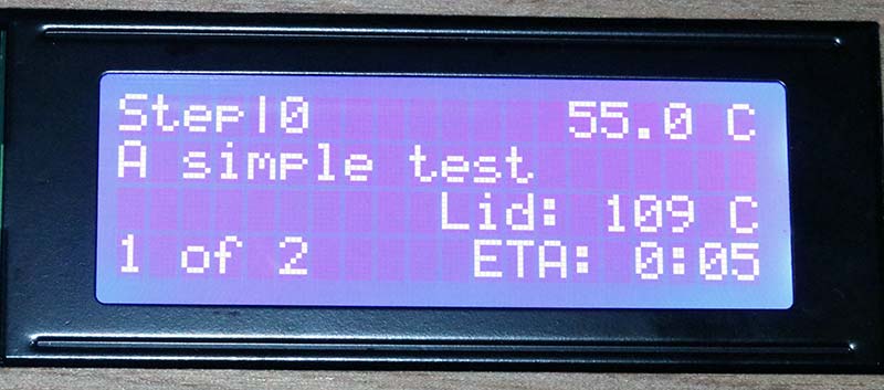
Photo 19. Display from dry run.
I have no reason to doubt the accuracy of the LCD readout. However, a full test of the system would require a calibrated thermal probe to verify the temperature shown on the LCD display. The ultimate test, of course, is using the thermocycler to amplify DNA. There’s no arguing with success.
DISCUSSION
The OpenPCR is a simple thermocycler. Comparable used thermocyclers are available on eBay for about half the price of this kit, but these machines are black boxes. More advanced PCR systems are available. While they can handle dozens of tubes and provide rapid changes in temperature and elaborate timing schemes, they can also cost upwards of $5K and more.
Of course, the hardware is half of the equation. In addition to protein sequences to amplify, you’ll need to create a chemical environment supportive of the PCR process.
Companies such as Chaibio.com (the supplier of the OpenSource PCR) offer buffers and other components in the form of mixes (see Photo 20). These mixes typically sell for upwards of $100 or more, but support over a hundred experiments.
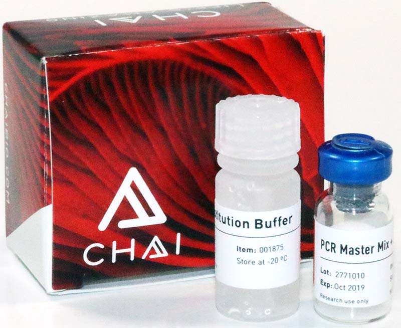
Photo 20. Buffer mix.
One of the problems with PCR supplies is that they must be kept frozen at -20°C; this means overnight shipping of expensive biologicals that could be ruined by a single exposure to high ambient temperatures — such as in the back of a delivery truck.
Some mixes (such as the one in Photo 20) are available in partially dry form, extending their longevity without need for expensive overnight delivery.
Good luck with your DNA experiments! NV
Downloads
What’s in the zip?
Bill of Materials