Antennas — whether you buy one or make one — are part of a system. In this article, I'll discuss the radio antenna and its role in a radio system. The information expressed here is based on my observation and tests over several years as an amateur radio operator, avid antenna experimenter, and inventor.
For simplicity, my focus here will be based on radios with 50 ohm outputs and readily-available 50 ohm coax cable. Many other antenna/coax combinations exist and will be mentioned briefly.
The Radio Antenna System
An antenna is more than just copper wire or aluminum tubing. It’s part of a system.
Typically, an antenna is the business end of a radio system. It starts with the radio receiver or transmitter and connects through a length of suitable cable. In some cases, it needs a matching device to transfer radio energy efficiently, which produces an ample signal and sends it out to the world.
Here are some thoughts on assembling a radio antenna system with a focus on reducing the known variants that are usually either overlooked or that can creep in when you're not looking. This discussion is focused on simple and available components. No math here — just some helpful observations from my tests over the years as mentioned.
Of course, this is not the only method of setting up an antenna system by a long shot, as there are many good resources out there. Be sure to check the References.
The Parts of the System
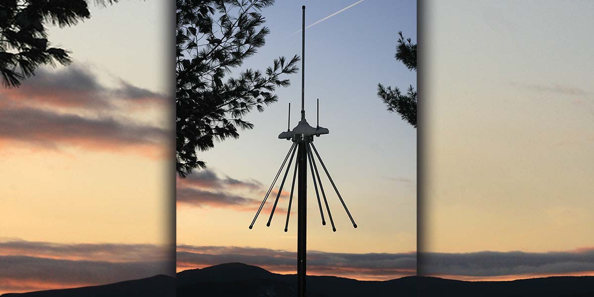
The Antenna Itself
Antennas have some interesting characteristics. One of the important ones is the value of the antenna's impedance at its feed point. For practical purposes, designers try for an impedance value around 50 ohms.
One of the main reasons is efficient power transfer. Since the impedance at the radio's output connector is typically 50 ohms and readily available coax cable is 50 ohms, we start there. Though other cable values are available — ranging from 75 ohms to 600 ohms — these are generally used in situations not covered here. These higher values can also require matching devices to transform the value to 50 ohms.
The value of impedance at the antenna feed point depends on many variables — not all of which can easily be controlled. This makes antenna system implementation a mystery to most, or at best, a trial and error fest. So, let's look at those things we can control and that follow a few simple considerations.
One thing I've noticed is that when radio operators use antenna tuners — whether manual or automatic — they are placed near the radio which is convenient from an operational standpoint. This works to a point but isn’t the most efficient approach. A better practice would be to put the antenna tuner at the antenna.
The reasoning is simple, but not always practical. If you have a radio with a 50 ohm output connected to a 50 ohm cable, you have an efficient power transfer or — as some call it — a good match (low SWR). With the antenna tuner at the unknown antenna feed point, it can do its job matching the 50 ohm cable to the antenna feed point impedance for optimum power transfer. Ideally, with an antenna of 50 ohms, the tuner isn't necessary unless you’re operating the antenna on multiple frequencies.
Cable Connection
Of course, 50 ohm coax cable isn't the only option to feed an antenna system. However, it’s just a conveniently available one. The main concern here is the quality of the product. Coax tends to have power losses associated with it. This is especially true at higher frequencies and with longer runs, and especially with an antenna impedance mismatch (high SWR).
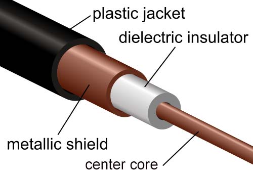
Coaxial cable.
So, the obvious suggestion here is to buy the best quality coax you can afford, keeping the length as short as possible. That means going to the larger diameter types that generally have lower losses. You lose some flexibility with the larger diameters, so keep this in mind when planning for routing through and around things.
As stated previously, power loss in the coax can be significant for long runs when the impedance mismatch (SWR) at the antenna is large. If your antenna system is going to be used for VHF or UHF frequencies, this is especially true. Since antenna tuners for these higher frequencies are not readily available, the quality of the coax is very important and, again, the shorter the length of the cable, the better.
Connectors
Personally, I prefer to use N-type connectors over the more common UHF connector for any antenna above 50 MHz because I find the N connectors more robust and a bit more weatherproof. They have a consistent match to 50 ohms well into the UHF frequencies. Be especially carefully with inexpensive UHF type connectors; I have found they can create problems all by themselves.
I also recommend waterproofing any connection that is outside. I make sure to tighten the connector firmly and then wrap it first with a self-sealing tape, then wrap it again with waterproofing tape that can handle UV exposure. If you haven’t done this and notice a fluctuation in signal strength or reflected power (SWR), check your connections. Before I used this double tape method, I was able to drain water from inside UHF connectors on several occasions.
Variations of the Theme
Matching Devices Other than Antenna Tuners
Baluns — short for "balanced to unbalanced" — typically are devices used to connect a two-element antenna like a dipole or its twin lead feed line (the balanced part of the antenna system) to an unbalanced coax cable. The term balanced antenna here can also mean an antenna that is electrically in balance with the surrounding environment, not necessarily an antenna with two equal length elements.
A balun can have an impedance matching ratio of 1:1, 4:1, 6:1, or even 9:1. The matching ratio can be a current or a voltage mode, with the current mode being preferred because of its broader performance characteristics.
For example, a dipole — two equal length elements — may have an impedance at its center feed point of 72 ohms. Here, a 1:1 balun would provide a good match to 50 ohm coax. However, this isn't the only variant here. There is a third signal we need to consider.
Things that Creep In (Besides Water)
Coax has a center lead conductor surrounded by another conductive shield. The transmitter signal operates between the two inner conductive surfaces of the coax. The external part of the shield is exposed to the radiated signal. Since RF signals prefer to ride close to the top surface of a conductor (called the skin effect), the signal can return to the transmitter through this outer path causing RF feedback at the radio.
A simple and effective way to reduce this effect (called common mode current) is to coil a few turns of the coax just below the feed point; this is called a choke balun.
Ferrite cores are a more effective way of reducing this common mode effect, but depending on the frequency of operation and the power level, care must be taken in their selection.
The Counterpoise Gift
If we have a reasonably well-designed antenna — one that can utilize a ground plane such as an elevated vertical with radials — it’s possible to put a counterpoise plane approximately 1/4 wavelength below the radials. This will also reduce the effect of the RF continuing down the outside of the coax.
J-pole antennas and long wires are very susceptible to this common mode effect and will be greatly enhanced by some method of choking the effects of RF on the outside of the feed line.
The Antenna Environment
The antenna support (whether a mast or strung from a tree) will require a plan, or at least you should think about it before you start.
Antenna masts — usually a metal tube attached to your house, chimney, or (if you're lucky enough) a tower — all become part of the antenna system.
Other metal objects near the antenna are part of the system as well. These include rain gutters, metal door frames, cars in the yard, and (in my case) barbeque grills.
Obviously, the closer these objects are to the antenna (1/8 wavelength or less), the more effect they will have.
For HF, this isn't usually too much of a problem, although a 1/2 to 3/4 wavelength distance or more away from the antenna is desirable.
For VHF and UHF, care must be taken to keep the antenna as far away as possible from metallic objects (like those pesky BBQ grills).
Grounding Your Mast and Antenna
Grounding a mast for static discharge is a very good idea on any antenna system. The caveat here is, does the now grounded mast become a tuned part of the antenna system, thus changing the resonance of the antenna and changing the SWR?
When mounting a VHF antenna on a universal mounting hub, I assemble the antenna, hub, and radials to a tripod mount. It turns out the upper part of the telescoping tripod is isolated from the lower part. The upper mast becomes a tunable sleeve, and as I move the mast up or down, it changes the resonant point and the SWR of the antenna.
Conclusion
The antenna is part of a radio system and needs to be considered in the whole approach. The antenna, cable, matching device, and environment are all part of this system.
For a simple approach to assessing an antenna as part of a system, I would first look at the frequency (or frequencies) of operation, the environment, the connection, and the antenna. The variants can be minimized, and hopefully have you operating successfully with minimal frustration. NV