In the ham world, there is probably nothing more boring than an antenna switch, except for maybe a dummy load. It just sits there all day waiting for a command to do something, hoping to connect with the antenna that helps pull in the “big contact.”
Finding a way to make something boring somewhat less boring is always a challenge. However, starting with a pretty good level of boredom allows a bit of room for taking a look at the details.
There has to be some sensible limits put into any design, so let’s look at what choices there were. To keep it simple, I wanted the power limit to be 1,000 watts. The current state of inexpensive relay technology doesn’t lend itself well to RF levels above 1,000 watts.
With the number of antenna selection choices of two, four, and six, the best number of antenna ports considering desktop operation and size is four. If you need more ports, cascade two units to make seven available.
The last major consideration was a USB connection. More and more stations have computers integrated into the daily operations, and USB seems an easy way to add computer control.
The result is the SW-4U: a four-position antenna switch with PC control via a USB connection. Standard SO-239 connectors are used for HF input and output, having less than 0.5 dB of insertion loss. The switch uses 16 amp relays to allow safe switching up to 1,000 watts. The circuit requires a 10-18 volt power supply (12 volt nominal) sourcing at least 500 mA. This switch can be controlled by an application program running on a standard Windows PC. The user interface shows four clickable buttons and an on/off switch. This allows you to control antenna selection directly from your PC.
Connected to your PC by a standard USB cable, the application allows you to select any of four antennas connected to the appropriate ports, or ground all for safety, and to power the switch on and off. When turned off or the DC is disconnected, the switch defaults to port 1.
Purpose: Why do we need it?
There are now and always have been a plethora of antenna switches, so why do we need one more? Remote switches can offer slightly less loss in some cases, but are more complicated, are expensive, and require remote power and switching control. Manual desktop switches are simple and common but, of course, aren’t computer controlled. The principal feature of this switch is PC control via USB, opening many opportunities for configuration.
Electronic switches use relays (usually controlled by a microprocessor), offering a wide range of capabilities. First, it can switch between antennas with the click of a button. The microprocessor prevents switching while RF is present, protecting your transmitter or amplifier. This switch measures the RF power and prevents switching above about 150 watts.
Another very useful control mode provided in this switch is by band. When you activate band control, the settings in the PC program will select an antenna automatically based on the frequency in use. For example, if you transmit on 80 meters and have Antenna 2 set for that band, the switch will automatically change to Antenna 2. If you set Antenna 3 to 20 meters, it will select Antenna 3 the first time you transmit on 20M. The ports are selectable for any combination of the 10 bands and four antennas through the PC software.
Discussion of Block Diagrams: How does it work?
RF input is switched between four outputs under PC control. Looking at the block diagram in Figure 1, we see the four antennas are switched using eight relays; each antenna port has two relays to help increase isolation between ports.
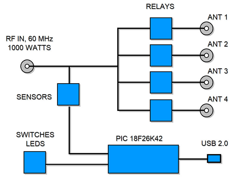
FIGURE 1. Block diagram of the switch design. The major sections include the processor and the RF switching relays.
The processor is a PIC18F26K42 with multiple inputs and outputs, making it run smoothly with a small C program compiled with MPLAB: a free C compiler available on the web from Microchip. The source code is available in the downloads. The frequency counter is connected via a level converter to protect the processor from any high voltage from the RF signal. Pulses are counted to calculate the frequency. Refer to my article in Issue-1 2019 for more design details on the frequency counter circuit.
For serial data, the USB port is a standard FT-230XS; opto-isolators on the input and output help protect your computer. The USB chip is powered from the USB port and provides three status indicators: power, RX, and TX. You can use these indicators for low-level troubleshooting if needed. To achieve the 1,000 watt level, we specify Schrack RZL heavy duty 16 amp DPDT relays, guaranteed for about 100,000 cycles. If you have this switch for 10 years (it’s very possible), you can switch each antenna 10,000 times per year, or about 30 times a day. That’s a lot of switching, but consider that kind of use if you’re running Automatic Link Establishment (ALE), or a mode that automatically changes the antenna. In that type of service, you could easily run through the expected service life of the relays in the first year.
The printed circuit board (PCB) layout is somewhat critical since we’re working with RF from 1 to 60 MHz. The chassis-mount S0-239 sockets are at board height, so we can keep the wire length from the connector to the PCB suitably short. After the RF reaches the PCB, we still need to keep the traces as short and direct as possible. There are two relays per port wired in series to help with isolation, with each pair switched together by a TPIC 595 relay driver. To help reduce the RF in the neighboring circuits, the ground plane outlines the RF section to create a “keep out” area; only RF and essential parts are allowed here.
The buttons for antenna selection are momentary contacts, so the USB can take control when commanded. Each antenna selection switch has an LED indicator associated with it. The power switch is hardwired to switch DC, but the LED is powered by the processor.
Software: Not too much?
Two pieces of software are required for the complete switch. The PIC processor is programmed in C; go to the downloads for the source code. The processor monitors both the front panel switches and the USB port. When either a physical button or software button is pressed, the unit selects the antenna. (Both programs and source code are available.)
The PC program allows remote control of the tuner. The program is written in BasicC and runs as an .exe file. From the PC, you can control the antenna switch position with a mouse or change control to the frequency counter. In this configuration, RF is sampled by the processor, the frequency is sent to the PC and mapped to your selected antenna, and the change antenna command is set to the switch. The safety section of the switch is a combination of hardware and software. A voltage sampler measures RF amplitude. Since it can’t be calibrated, it’s used as a relative level sensor to indicate if more than about 150 watts has been detected.
When the level is over 150 watts, the software in the processor will not allow the relays to change. This greatly reduces arcing on the relay contacts, and helps protect your transmitter or amplifier.
The USB connection is a standard FX-230 USB 2.0B connector. To reduce interference, it’s important to use a quality shielded cable from the antenna switch to the computer. Most current PCs have USB drivers that will work well, but you may need to download and install a new version from the FTDI website.
Discussion of the Details: What do the geeks want to know?
The heart of the switch is obviously the relays. The Schrack RZL units are very good up to about 60 MHz. Another reason we chose this particular relay is that the internal contact bars are very short, helping to provide good isolation for our application. The schematic in Figure 2 shows the switch configuration with Antenna 1 connected when DC is removed.
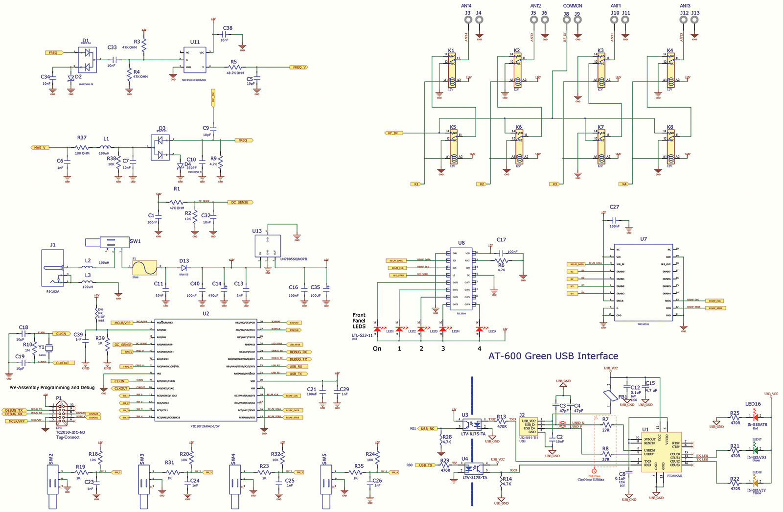
FIGURE 2. Schematic of the antenna switch. Notice the USB section is isolated from ground.
The RF power is limited by the relays to 1,000 watts, but the PCB is laid out to handle up to 1,500 watts to provide a safety margin. To keep the impedance near a constant 50 ohms on the PCB, we use strip line technology with the 0.100” RF traces and 0.150” spacing. Mounting the SO-239s as close as possible to the PCB also helps keep everything at 50 ohms.
The maximum loss at 60 MHz is about 0.5 dB (see the graph in Figure 3), but there are ways to make that a little better. One of the factors in calculating loss is the conductor length; shorter wires are always better when conducting RF. Since the distance from the common connector to Antenna Port 1 is shorter than the distance from the common to Antenna Port 3, there will be less loss when Antenna Port 1 is used. It’s not much difference, but it’s worth noting. With less loss, the impact on SWR is much less noticeable.
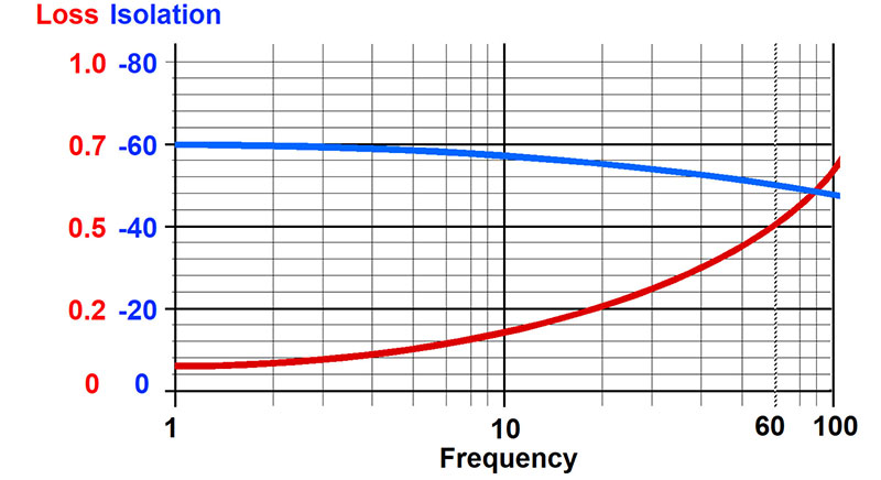
FIGURE 3. Performance curves from 1 to 60 MHz. Blue is isolation between ports in db and red is signal loss in db.
The last detail we need to consider is isolation (again refer to Figure 3). While a single relay can provide about 40 dB of isolation, putting two in series adds another 20 dB: a total of 60 dB between ports. This may sound like a lot, but it’s not always ideal.
For a single radio and its antennas, this is great! If you hear a tiny bit of signal coming from an antenna that is not selected, it’s okay and means your radio is extremely good at picking up these low-level signals.
Doing this in reverse for one antenna and four radios is different. A tiny bit of signal will always leak through and will be fairly large with a 1,000W transmitter. With 60 dB of isolation, leakage is still one milli-watt and dangerous to put on the input of your radio. At 100 watts, you could get 0.0001 watts to the radio. There is no standard, but the industry seems to be happy with 70 dB for 1,000 watts. With the SW-4U only having 60 db of isolation, limit the power to 100 watts when in the multiple radio configuration.
Go and Do: What is needed to complete?
There are a couple of easy ways to build this project. The Gerber files are included in the downloads to get an exact copy of the PCB made. If you prefer, a kit is available from the Nuts & Volts webstore.
Be sure to look at the details of these files; 3D models are included as well as dimensioned drawings for the enclosure. You literally could send these files to a manufacturing company and they would make you however many kits or assembled units you need. The cost would be pretty high in the 2-3 quantities, but if you come back and read this article 10 years from now and want one, you could actually do that. If you end up making this project a kit for your club, be sure to have the tiny SMT parts pre-installed.
Building this project is mostly straightforward. There are about 50 total parts with 25 of the tiniest parts pre-installed. The remaining parts have about 200 solder joints, making this a medium-level kit. Soldering skills are required but use of large through-hole parts permits a wide range of construction skill levels. The 3D model shows the parts placement in detail. Solder pads are at least 0.100” apart and a solder mask prevents wicking. If you’ve never soldered before, this would be a great project to have an Elmer walk you through the process.
Some of the parts have a polarity that indicates a certain way they need to be inserted onto the PCB. These include the electrolytic capacitors (C12, C22, C15, and C14) and the diodes (D1, D3, D4, D5, D7, and D8). Be sure to note pin 1 on each of the chip sockets as they “will” go in backwards, but may cause confusion if you need to find pin 1 later. Once built, desktop testing is simple. Connect 12 volts DC to J2. Press the power button and the power LED will come one. The last selected antenna LED will also come on. Press the antenna buttons and listen for the relay’s click each time it changes.
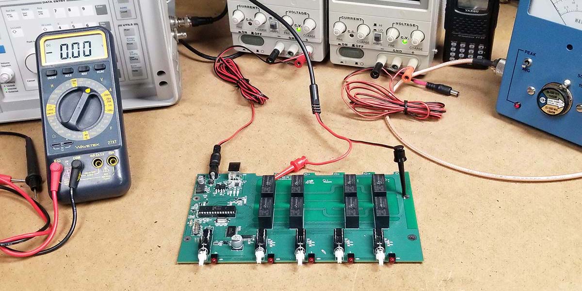
For RF testing, connect the switch between your radio and antenna as shown in Figure 4. Before transmitting, check your antennas on receive to see if they’re behaving as expected. Try a couple of different bands on each antenna to make sure.
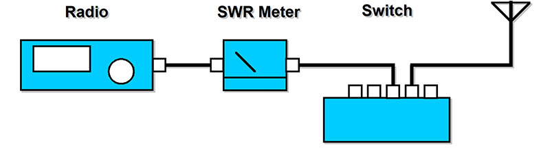
FIGURE 4. Testing the four-position switch is easy with your radio, antenna, and an SWR meter.
Once it’s all checked out, transmit a carrier signal at about 10 watts on 14 MHz. Check your SWR to see if it shows what you would expect. If it’s fine, move up to 100 watts and test more. There’s no good way to jump from 100 watts to 1,000 watts for testing other than keying the mic and seeing how it does.
Be very careful with this kit (if you purchase one) and your transmitter. Even 100 watts can give you a nasty RF burn on your fingers. A thousand watts can easily send you to the hospital, so never operate or troubleshoot the switch with the lid off. Connect the USB to your computer and switch, then start the PC program in Figure 5.
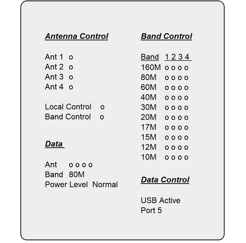
FIGURE 5. PC program controlling the switch via USB.
It will show you the current antenna position and allow you to select the position by clicking the buttons. You can also set up the switch to read the frequency and change the antenna by band. Each of the four antennas can be assigned to any of 10 different bands.

View of parts for assembly from the 3D model.
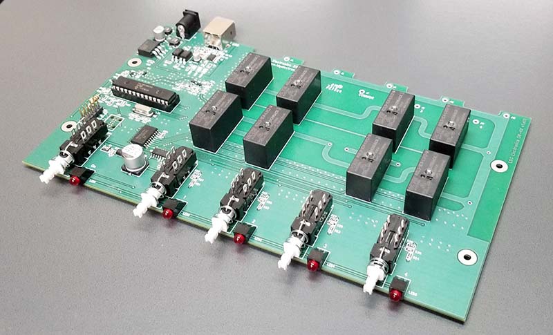
Completed unit.
Final Thoughts
This would be a great project for a two-part “Kit Night” for your radio club. Start a “Kit Committee” that oversees a group-buy for a few orders. One person can get the PCB while another collects the parts. The first night could be for distributing the parts of the kits and giving a 10 minute overview on the project and answering a few questions from the builders. Take a few minutes at the next meeting to show off the completed units and help test those that need a few touch-ups with the solder iron.
The SW-4U can provide a great deal of satisfaction by building something that will actually be useful in your station for years to come. The feature set is as good as any other kilowatt switch and the USB control opens up many possibilities for an inexpensive remote coax switching matrix. NV
| Qty |
Designator |
Comment |
Description |
Mouser Part# (unless specified) |
| 6 |
C1, C16, C17, C21, C27, C40 |
CAP CER 0.1 µF 50V X7R 0805 |
CAP CER 0.1 µF 50V X7R 0805 |
Mouser 603-CC805KRX7R9BB104 |
| 7 |
C2, C7, C11, C32, C33, C34, C38 |
10 nF, CAP CER 10 nF 50V X7R 0805 |
CAP CER 10 nF 50V X7R 0805 |
80-C0805C103K5R |
| 2 |
C3, C4 |
47 pF |
47 pF ±10% 100V Ceramic Capacitor C0G, NP0 0805 (2012 Metric) 47 pF ±10% 100V Ceramic Capacitor C0G, NP0 0805 (2012 Metric) |
581-08051A470KAT2A |
| 4 |
C5, C9, C18, C19 |
CAP CER 10 pF 500V NPO 0805 |
CAP CER 10 pF 500V NPO 0805 |
603-CC805JRNPOBBN100 |
| 8 |
C6, C13, C23, C24, C25, C26, C29, C39 |
CAP CER 1,000 pF 50V X7R 0805 |
CAP CER 1000 pF 50V X7R 0805 |
80-C0805C102K5R |
| 2 |
C8, C12 |
0.1 µF |
CAP MLCC 0.1 µF 16V X7R 1206 |
77-VJ1206Y104KXJPBC |
| 1 |
C10 |
CAP CER 330 pF 500V NPO 0805 |
CAP CER 330PF 500V NPO 0805 |
603-CC805JRNPOBBN331 |
| 1 |
C14 |
CEL |
CAP ALUM 470UF 20% 25V SMD |
647-UWT1E471MNL1S |
| 1 |
C15 |
4.7 µF |
Aluminum Electrolytic Capacitors - SMD 25 volts 4.7 µF 4x5.4 20% |
647-UWT1E4R7MCL1B |
| 1 |
C35 |
CAP ALUM 100 µF 20% 25V SMD |
CAP ALUM 100 µF 20% 25V SMD |
647-UWT1E101MCL1GS |
| 2 |
D1, D3 |
BAS70-04 |
DIODE SCHOTTKY 70V DUAL SOT23 |
821-BAS70-04RFG |
| 2 |
D2, D4 |
ZENER_BZT52C3V0-7-F |
DIODE ZENER 5.1V 1W SOD123 |
833-1N4733AW-TP |
| 1 |
D13 |
DIODE SCHOTTKY 60V 1A DO214AC |
DIODE SCHOTTKY 60V 1A DO214AC |
Digi-Key SS16-E3/61TGITR-ND |
| 1 |
F1 |
FUSE |
|
Digi-Key F4146TR-ND |
| 1 |
FB1 |
MI0805K601R-10 |
FERRITE BEAD, SM |
875-MI0805K601R-10 |
| 1 |
J1 |
PJ-102A |
CONN PWR JACK 2x5.5 MM SOLDER |
490-PJ-102A |
| 1 |
J2 |
USB |
USB Connectors USB 2.0 type B jack 4-pin horizontal TH |
490-UJ2-BH-1-TH |
| 10 |
J3, J4, J5, J6, J8, J9, J10, J11, J12, J13 |
1 |
HOOK-UP WIRE for RF 20AWG SOLID PVC 100 ft SPOOL RED |
602-1563-100-03 |
| 1 |
J14 |
MOLEX 15-91-6102 |
Headers & Wire Housings 10CKT VERT DR HDR |
538-15-91-6102 |
| 8 |
K1, K2, K3, K4, K5, K6, K7, K8 |
12V |
RZ Power PCB Relay 5 mm double pinning, 16A 1 pole 1 Form C (CO) contact non-latching |
655-RZL3-1C4-L012-W |
| 1 |
L1 |
IND_0805 |
FIXED IND 100UH 130 MA 9.1 OHM |
963-CB2012T101K |
| 2 |
L2, L3 |
L |
FIXED IND 100UH 660 MA 780 MOHM |
963-NR6028T101M |
| 5 |
LED1, LED2, LED3, LED4, LED5 |
LED R/A TH Red LITEON_LTL-523-11 |
LED RED R/A THROUGH HOLE |
859-LTL-523-11 |
| 1 |
LED16 |
IN-S85ATR |
LED RED CLEAR 0805 140 mcd |
743-IN-S85ATR |
| 1 |
LED17 |
IN-S85ATG |
LED GREEN CLEAR 0805 600 mcd |
743-IN-S85ATG |
| 1 |
LED18 |
IN-S85ATY |
LED YELLOW CLEAR 0805 115 mcd |
743-IN-S85ATY |
| 3 |
R1, R3, R4 |
RES SMD 47K OHM 1% 1/8W 0805 |
RES SMD 47K OHM 1% 1/8W 0805 |
603-RC0805FR-0747KL |
| 7 |
R2, R18, R20, R24, R32, R38, R39 |
RES SMD 10K OHM 5% 1/8W 0805, RES SMD 1K OHM 1/10W 0805 |
RES SMD 10K OHM 5% 1/8W 0805, RES SMD 1K OHM 1/10W 0805 |
603-RC0805JR-0710KL |
| 1 |
R5 |
RES SMD 48.7K OHM 1% 1/8W 0805 |
RES SMD 48.7K OHM 1% 1/8W 0805 |
603-RT0805FRE0748K7L |
| 4 |
R6, R9, R14, R28 |
RES SMD 4.7K OHM 1% 1/8W 0805, 4.7K |
RES SMD 4.7K OHM 1% 1/8W 0805, RES 4.7K OHM 1/8W 5% 0805 SMD |
603-RC0805FR-074K7L |
| 2 |
R7, R8 |
27R |
27 ohms ±10% 0.125W, 1/8W Chip Resistor 0805 (2012 Metric) Automotive AEC-Q200, Pulse Withstanding Thick Film |
603-SR0805KR-0727RL |
| 1 |
R10 |
RES SMD 1M OHM 5% 1/8W 0805 |
RES SMD 1M OHM 5% 1/8W 0805 |
603-RC0805JR-071ML |
| 5 |
R13, R21, R22, R25, R29 |
470R |
470 ohms ±5% 0.125W, 1/8W Chip Resistor 0805 (2012 Metric) Moisture Resistant Thick Film |
603-RC0805JR-07470RL |
| 4 |
R19, R23, R31, R35 |
RES SMD 1K OHM 5% 1/8W 0805 |
RES SMD 1K OHM 5% 1/8W 0805 |
603-RC0805JR-071KL |
| 1 |
R37 |
RES SMD 100 OHM 5% 1/8W 0805 |
RES SMD 100 OHM 5% 1/8W 0805 |
603-RC0805JR-07100RL |
| 1 |
R40 |
10K |
RES 10K OHM 1/4W 5% CARBON FILM |
603-CFR-25JR-5210K |
| 5 |
SW1, SW2, SW3, SW4, SW5 |
SW_F2UEE |
SWITCH PUSH DPDT 0.5A 125V |
611-F2UEE |
| 1 |
U1 |
FT230XS-R |
USB Interface IC USB to Basic Serial UART IC SSOP-16 |
895-FT230XS-R |
| 1 |
U2 |
PIC18F25K22 |
IC MCU 8BIT 64KB FLASH 28SDIP |
579-PIC18F26K42-I/SP |
| 2 |
U3, U4 |
LTV-817S-TA |
Photocoupler a.k.a., Optoisolator Transistor Output 5,000 Vrms 1 channel 100 mil-pitch SOP4 |
859-LTV-817S-TA |
| 1 |
U7 |
TPIC6B595 |
IC PWR 8-BIT SHIFT REGIS 20-SOIC |
595-TPIC6B595DWRG4 |
| 1 |
U8 |
TLC5916 |
IC LED DRIVER LIN 120MA 16SOIC |
595-TLC5916IDR |
| 1 |
U11 |
SN74LVC1G07 |
IC INVERTER 1CH 1-INP SOT23-5 |
595-LVC1G04QDBVRQ1 |
| 1 |
U13 |
LM7805SX |
IC REG LIN 5V 1.5A DDPAK/TO263- |
595-LM7805SX/NOPB |
| 1 |
Y1 |
XTAL_B |
CRYSTAL 64.0000 MHZ 18PF SMD |
717-9C-64.000MAAJ-T |
A kit for this project is available in our webstore.
Downloads
Schematic
Code files
Templates