I’m old enough to have experienced black and white television, the introduction of color television, the very first post-WWII gasoline “shortage” and rotary “Princess” telephones. I also remember when AM radio was king and only uppity college kids listened to FM. In fact, I recall when an AM radio was all the entertainment you would ever find installed in the automobile dashboards. In my youth, a CB radio was your cell phone and your iPod was an eight-track tape player. My buddies and I questioned the ability of those tiny new audio cassettes to sound as good as our vinyl records and quarter-inch reel-to-reel tapes. Oh yeah, that vinyl album costs $3.98, which I considered highway robbery. After all, gasoline prices had just been raised and I was paying 25 cents a gallon for that 23 cent-a-gallon gas I just bought last week. With those high prices, how could I afford to buy the latest tunes and cruise the Dairy Queen parking lot in my brand new $4,000 Oldsmobile 442?
Yes, I’m old and I wish I still had that 442. However, I’m not old enough to remember ever being forced to assemble an electronic circuit on a piece of wood. Depending on who you trust and what you believe, electronic assembly — both hobby and professional — began with a foundation of an easily acquired and just as easily cut-to-size slab of wood. In addition to being sturdy, workable, cheap, and plentiful, dry wood is a fairly good insulator, which made it an ideal choice for supporting the screw-down point-to-point construction techniques used at the time.
Modern breadboard derivatives are constructed with plastic that is formed around a spring-loaded metal conductor. The plastic is molded to form rows and columns of single-pin, spring-loaded sockets that are designed to get an electrical grip on standard hookup wire. The plastic and metal breadboard sockets are also amiable to common leaded electronic components such as resistors, transistors, and capacitors. Note that I listed the components as “leaded.” You can’t squeeze a solderless breadboard connection out of an SMT resistor, an SMT transistor, or an SMT capacitor without first soldering some wires to them.
Modern plastic-based solderless breadboards are intended to be reusable universal circuit assembly platforms. I often use solderless breadboards for quick and dirty proof of concept verification. As you can see in Photo 1, I sometimes use plastic solderless breadboards as a reusable breadboard area on development board projects.

PHOTO 1. This Xilinx CPLD development board includes an integral solderless breadboard. The solderless breadboard allows the designer to quickly build up peripherals and interfaces to interact with the development board’s CPLD.
Although the modern plastic-based breadboards are excellent platforms for most prototyping tasks, we won’t be breadboarding our circuit on a solderless breadboard this time around.
No Splinters
Now that we’ve eliminated solderless breadboards from our immediate discussion, you can put that circular saw away as we won’t be screwing down any of our electrical components into a slab of pine. We’re about to delve into some 21st century breadboarding.
If you’ve ever shopped for project parts at RadioShack, you are already familiar with their breadboards. RadioShack calls them perfboards. We’ll call them breadboards. An example of a RadioShack breadboard caught the attention of my camera in Photo 2. The phenolic RadioShack breadboard depicted in Photo 2 is most likely designated as FR-2; FR in this case indicates it is flame resistant and 2 is telling us that the perfboard is made of synthetic resin bonded paper.
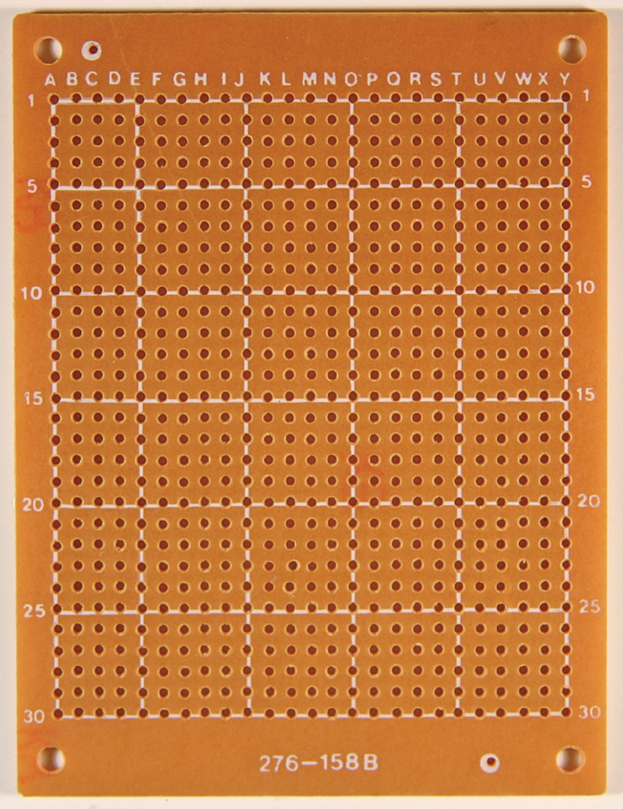
PHOTO 2. The copper pads on the other side of this perfboard are not solder-plated. So, you’ll need to clean the copper pads with a Scotch-Brite pad before attempting to do any serious breadboarding with this perfboard.
Other than being rated as FR-2, the phenolic breadboard in Photo 2 is single-sided. That is, it presents unplated copper pads on one side only. Since there is only copper on one side of the board and there is no plating on the copper pads, a plated-through pad cannot exist on this breadboard. Thus, the RadioShack breadboards are equivalent to a single-layer printed circuit board (PCB) with no plated-through holes. These boards work very well for general-purpose breadboarding of standard leaded components. Some of the breadboards can also handle the mounting of SMT components if you choose a suitable copper pad arrangement.
If you don’t have access to a local RadioShack, you most likely use mail-order electronic vendors such as (www.jameco.com) or Mouser (www.mouser.com) to get your electronic parts fix. You will find a breadboard for almost any application within the pages of their catalogs. For instance, you’ll find a large selection of breadboards constructed using epoxy resin. These glass/epoxy breadboards are normally designated FR-4. The number 4 signifies that the PCB material is composed of woven glass reinforced epoxy resin. An FR-4 breadboard posed for Photo 3. The good news is that all of the basic techniques associated with breadboarding can be performed equally as well with an FR-2 breadboard as they can with an FR-4 breadboard. However, a breadboard with plated-through holes does have its advantages.
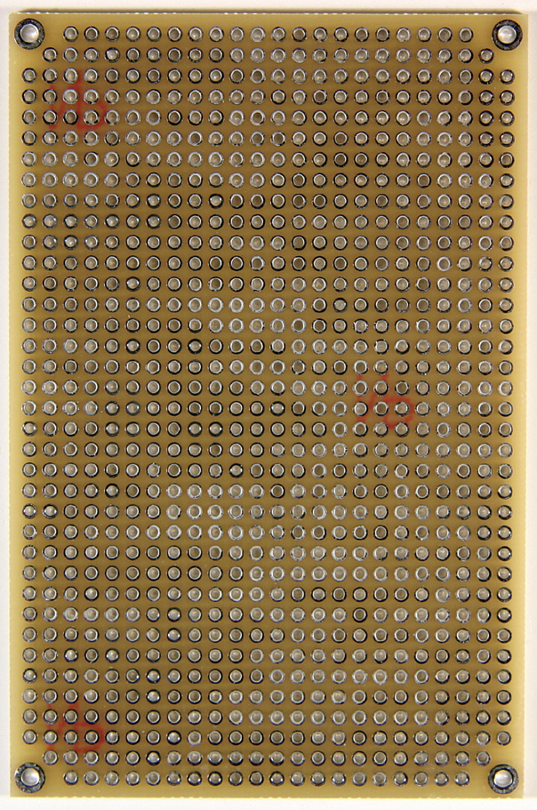
PHOTO 3. This FR-4 breadboard consists of 0.046 inch diameter plated through-holes, which are dispersed on 0.1 inch centers. The through-hole solder plating enables electrical continuity between both sides of the breadboard at every hole. Thus, this breadboard can be considered as double-sided with plated through-holes.
Tooling Up
The goal of breadboarding is to mount electronic components on a supporting substrate and make all of the necessary electrical connections that result in a functional electronic device. In most cases, a length of wire is used to make an electrical connection between components mounted on a breadboard.
Before the wire is installed in the circuit path, the wire must be cut to length and if the wire is insulated, it must be stripped at both ends to expose enough of the wire to attach and solder it to each end of the electrical connection. Cutting, stripping, positioning, and soldering wires make up the bulk of breadboarding work. All of the mail-order electronics outlets and local RadioShacks offer electronic hand tools to help you with manipulating breadboard wiring.
I have also found that local home centers stock high quality wire cutters, lead cutters, and pliers that work well in the breadboarding environment. Since good solder joints are a must for point-to-point electronic assembly, I suggest investing in a good quality soldering station. Check the pages of Nuts & Volts and you’ll find a number of vendors that can help you put a reliable soldering station on your bench.
The bottom line in tool selection is quality. I know from experience that when those cheap lead cutters go dull in the middle of an important breadboarding project, you’ll wish that you had spent that extra couple of dollars for a higher quality tool.
Breadboarding 101
I’m not going to insult your intelligence by detailing the process of mounting a component on a breadboard and wiring it in. However, I will pass along some breadboarding wisdom:
- Rat's nest wiring techniques insure breadboarding failure.
- Poor component layout insures breadboarding failure.
- Sloppy soldering techniques insure breadboarding failure.
- Never begin a breadboarding project until you have all of the components in hand.
- Route your breadboard wiring as if you were laying out printed circuit board traces.
You’ve finished wiring up your circuit and nothing works. If you’ve haphazardly laid in your connections, you’ll have to dig out an ohmmeter to find and check your circuit paths. To avoid having to tear apart your work to find a wiring bug, try to lay out your point-to-point wiring just as if each wire was a trace on a PCB. If you took the time to logically locate the electronic components and connectors on your breadboard, tracking wires on the breadboard as if they were PCB traces is logical and comes naturally.
Soldering in a rats nest of wire will certainly result in a shorted pair of wires or a cold solder joint. Proper component layout and methodical wire routing will allow you to solder in the clear. Creating a clean and logical component layout on your breadboard cannot be achieved if you don’t have all of the electronic components you need to mount on the breadboard. Without a complete component layout, you can’t make logical and clean wire routing decisions.
Working Smart
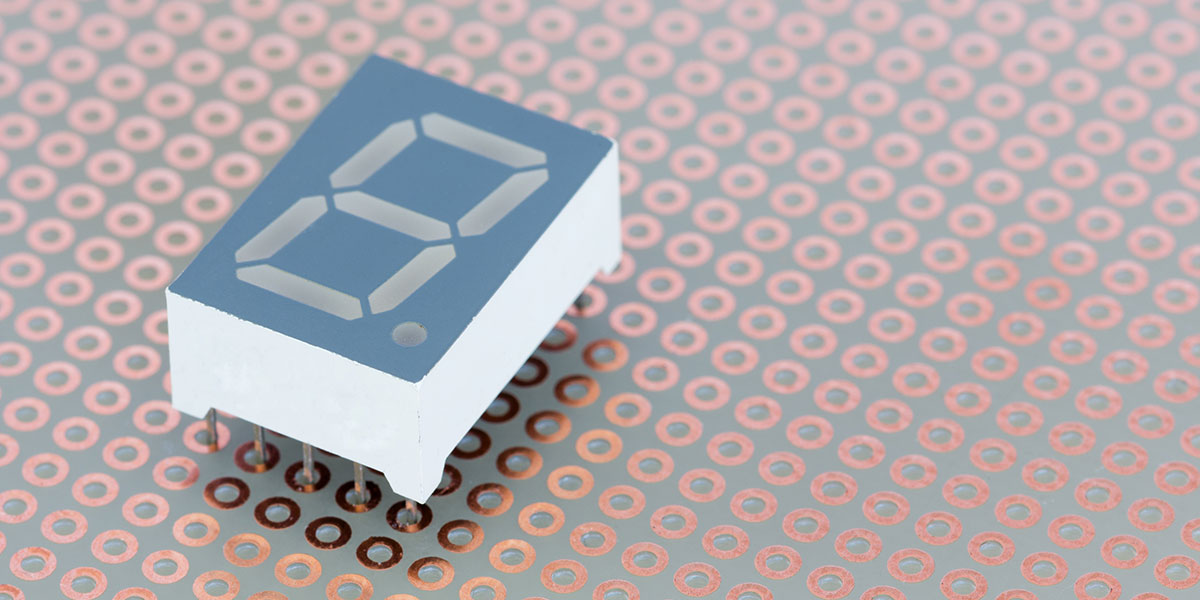
It may be painful at first, but combining SMT components with a plated through-hole breadboard like the one you see in Photo 3 can eliminate a large portion of the labor-intensive wire cutting, wire stripping, wire positioning, and soldering associated with breadboarding. Consider the LED/resistor combination I’ve laid down on a double-sided FR-4 breadboard in Photo 4.
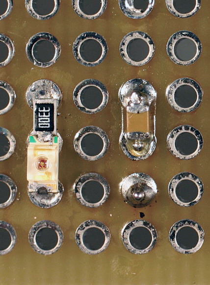
PHOTO 4. The 0805 SMT components fit nicely between the 0.1 inch pitch plated through-holes of this breadboard, which happens to be the same FR-4 breadboard you see in Photo 3. The LED proves that you can also squeeze in larger 1206 SMT components between the holes. The ability to directly connect SMT components to each other on the breadboard eliminates wire, saves time, and makes the component layout neater and more compact. Plated through-holes also allow electrical access to components from both sides of the breadboard.
The LED is mounted on a 1206 SMT package. The LED’s 330W current limiting resistor is packaged in 0805. There are a couple of things I want to bring to your attention concerning the LED and its companion current limiting resistor. Note the absence of wire connecting the LED and the resistor. The other cool thing here is that electrical access to the LED’s anode and cathode are available on the opposite side of the breadboard. The same holds true for both nodes of the resistor.
Moving to the right of the LED/resistor pair, you see a 0.1 µF ceramic capacitor, which is packaged as 0805. In this breadboard connection simulation, the cap is representing a power supply bypass capacitor on duty between the VDD and VSS pins of a PIC18F2620 microcontroller, which would be mounted in a socket on the opposite side of the breadboard.
Again, note the absence of connecting wires between the capacitor and the PIC18F2620’s socket pins. No cutting, stripping, or soldering of wire was necessary as I simply nudged the capacitor between the socket pins and soldered the capacitor into the circuit. Photo 5 shows us how important it is to select components that complement the structure of the breadboard.
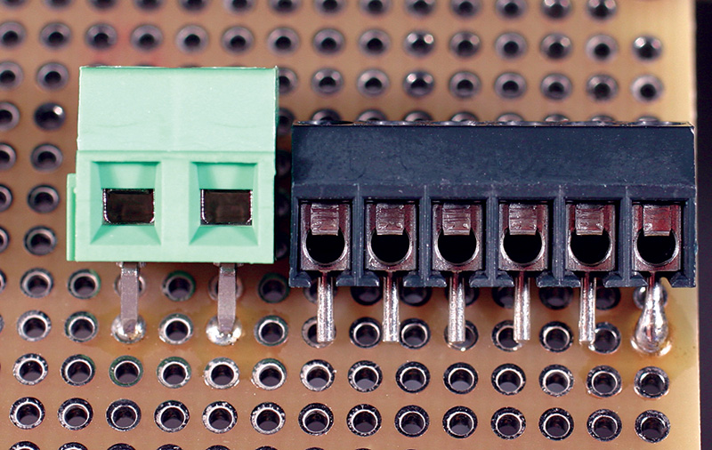
PHOTO 5. The two-position 0.20 inch pitch screw terminal block is one of many configurations that you can get from Phoenix Contact. This particular interlockable two-position screw terminal block is Phoenix part number 1729128. The screw terminal block is designed to interlock into another like screw terminal block. For instance, you can make a four-position screw terminal block by just using two 1729128 screw terminal blocks.
The screw terminal block on the left is designed to mate with a 0.150 inch pitch hole pattern. It’s rather obvious that we would have to break out the Moto-Tool to force fit this pitch screw terminal block onto our 0.01 inch pitch breadboard. It’s much easier to drop in the 0.02 inch pitch screw terminal block on the left.
The more components you have to mount, the more stuff you have to interconnect. You can eliminate having to install power supply regulation circuitry on your breadboard by powering your breadboard with a regulated +3.3 VDC or +5 VDC wall wart. Today’s PC switching power supplies are smaller and cheaper than their forefathers. Thus, you can also opt to adapt your breadboard to accept regulated +5 VDC power directly from an industry standard PC power supply interface.
Did you know that you can power your breadboard with regulated +5 VDC supplied by a PC USB interface?
I’ve assembled all of the aforementioned power interfaces on a breadboard in Photo 6.
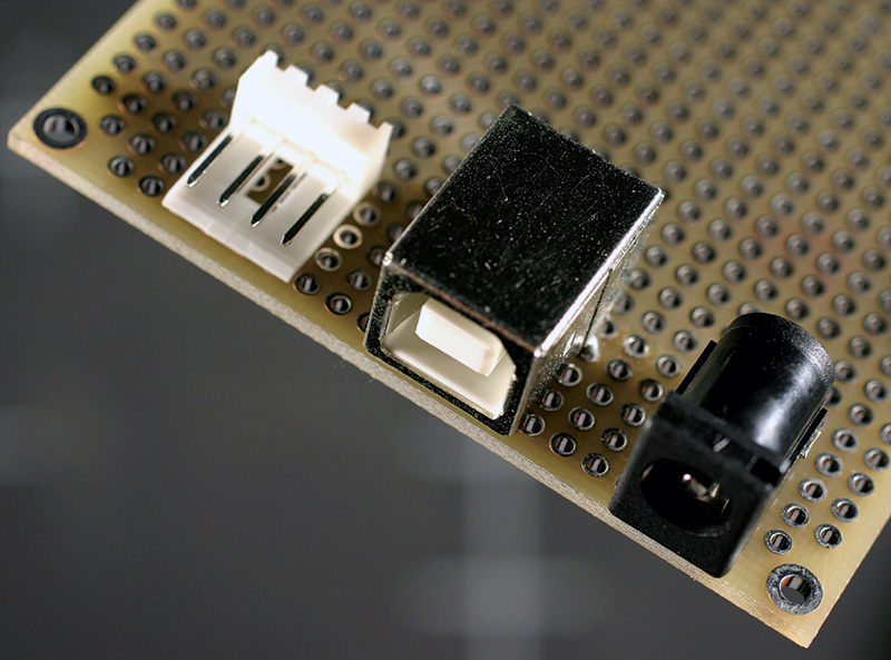
PHOTO 6. The four-position diskette drive power connector is something we’ve been plugging into for years. You can get this power connector and its mating plug from Jameco. The center power receptacle is actually a Type-B USB connector. The business end of a wall wart power cable mates nicely with the industry standard 2.5 mm male power jack.
The four-pin diskette drive interface is a no brainer as its pins are on 0.1 inch centers and industry-standard PC power supplies are identical when it comes to the diskette drive power interface. All that’s left for you to do is wire your breadboard power rails into the four-pin diskette drive power connector’s power and ground pins. Depending on which of the diskette drive power interface pins you connect, you’ll get +12 VDC or +5 VDC. So, be careful. Believe it or not, the Type-B USB connector is 0.1 inch friendly. Two of the USB connector’s four pins — which sit on 0.1 inch centers — carry +5 VDC (pin 1) and ground (pin 4). I had to break out the Moto-Tool to mount the 2.5 mm male power jack. This power jack allows you to power your breadboard from the wall wart of your choice.
How I Do It
There’s a breadboard behind every PCB I present in my Nuts & Volts and SERVO Magazine articles. Needless to say, I’ve done my share of breadboarding. I use 30 AWG Kynar wirewrap wire to make my breadboard signal connections. The Kynar insulation is easily deformed by the direct heat of a hot soldering iron. Thus, it is possible to accidentally overheat it and compromise the wire’s insulation by creating a void.
It’s uncanny, but those insulation voids always seem to create shorts to nearby exposed connections on my breadboards. If things on your breadboard are squirrely and you can’t find a logical reason why, check for wires that are stuck together or stuck to a neighboring solder connection. The insulation voids usually occur at those points.
If the breadboard requires a power and ground bus, I complete the component layout and then route the power and ground busses on the breadboard copper using 22 or 24 AWG tinned copper bus bar.
Working smart also includes being smart when it comes to tool selection. I consistently use the following breadboarding tools:
- PanaVise Electronic Work Center with 315 Circuit Board Holder
- Variable Speed Dremel Moto-Tool
- Metcal MX-5005 Soldering/Rework System
- Crescent Hand Tools (Home Depot)
Over the years, I’ve developed breadboarding methods and habits that work well for me. As time passes and you do more and more breadboarding, you will benefit from your experiences, as well.
By the way, if you’re having trouble finding that FR-4 plated through-hole breadboard I’ve been talking about in the catalogs, stop looking. I’ve supplied an ExpressPCB file in the downloads that will allow you to make one (or a few) of your own. See you later ... I’ve got some breadboarding I have to do. NV
Downloads
Breadboarding (How To: Perfboard PCB)