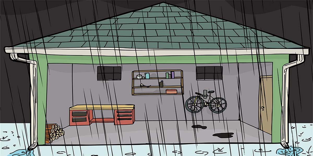
Automatic garage door openers can be a real blessing. I know, I feel that way every time I drive home in the rain. As convenient as they are, they are also a potential danger. Everyone — at one time or another — has gotten distracted and failed to close the garage door. An open garage door is an invitation for thieves and vandals. And don’t forget the mischief birds, cats, raccoons, and other animals can cause in your garage. So, I decided it was time to build a circuit that would close my garage door when it was unintentionally left open.
Investigating My Automatic Garage Door Operator
My goal was to design an automatic closer circuit that was simple and reliable. Because it is a safety device intended to compensate for my forgetfulness, I didn’t want to power it with batteries that I would have to remember to change in the first place. If the closer could be powered by the garage door opener itself, that would be ideal. I have a Genie radio-controlled automatic garage door operator. Like every automatic garage door operator, it also has a local normally-open pushbutton to open and close the door.
The Genie manual instructs the installer to connect the local pushbutton to the two screw terminals labeled PUSH BUTTON and COMMON. Using a voltmeter, I measured 19 VDC between COMMON and PUSH BUTTON. Using an oscilloscope, I observed this voltage to have approximately 2V of ripple (18V-20V) with peaks about every 8.3 milliseconds, suggesting it is the output of a full wave rectifier. Placing a variable load between PUSH BUTTON and COMMON, I recorded the voltage and current as a function of the load resistance (Figure 1). The garage door opener didn’t trigger until the PUSH BUTTON voltage was 0.3V or less. The maximum current of 10 mA available from PUSH BUTTON told me a low power closer circuit could be powered from that line.
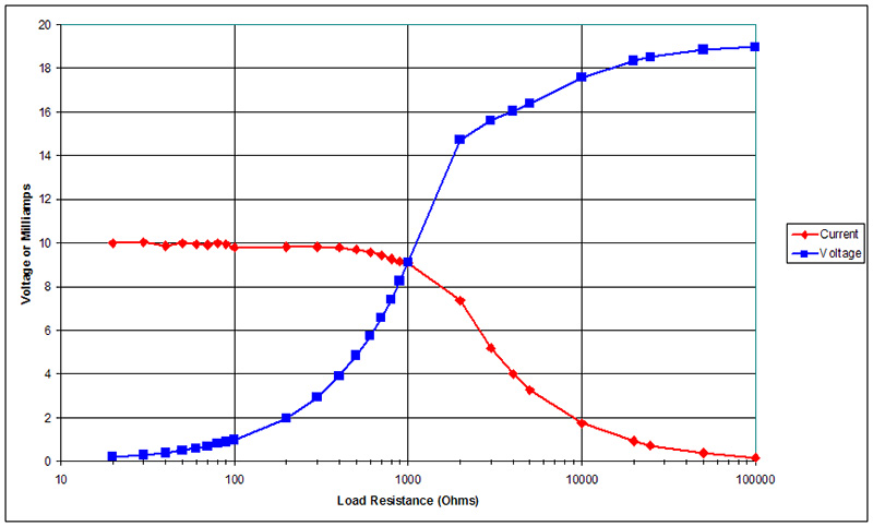
FIGURE 1. Voltage and current available on the PUSH BUTTON output of my Genie garage door operator as a function of load resistance.
Design and Build
I designed the closer circuit using a CMOS 4060, 14-stage binary counter and oscillator, shown as U2 in Figure 2.
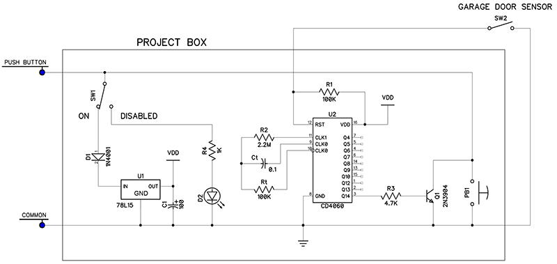
FIGURE 2. Schematic for the garage door closer circuit.
The datasheet gives the formula for the oscillator frequency as Fosc = 1/(2.3*Rt*Ct). The values shown in the schematic approximate a frequency of 43 Hz. A 14-stage binary counter can count to 16K which means the most significant bit’s output (Q14) will go high at count 8192. When Q14 goes high, it turns on transistor Q1which grounds the PUSH BUTTON input to the automatic garage door opener, causing the garage door to close.
How long does that take? At 43 Hz, the period (one count) is 23.25 milliseconds; 8192 counts = 190.5 seconds = 3 minutes and 10.5 seconds. Note that when Q1 turns on, it effectively shorts out the power supply for the closer circuit. The Vdd supply for U2 must persist long enough for the automatic garage door operator to react to the short on PUSH BUTTON. C1 stores enough charge to keep Q1 turned on for more than 100 milliseconds. D1 prevents reverse current flowing from C1 through U1.
Speaking of Vdd, the 4XXX series of CMOS logic is designed to operate from three to 15 volts. I included the 78L15 (U1) low power linear regulator to insure that Vdd did not exceed the maximum operating voltage. When I want to keep the garage door open for an extended period — like when I am mowing the lawn or washing the car — I can flip switch SW1 to the disable position. This removes power from the closer circuit and lights a red LED warning me the closer is disabled. Even when the closer circuit is disabled, the garage door can still be opened or closed by pressing pushbutton PB1. When you think about it, the closer circuit is nothing more than a fancy way of pressing the local pushbutton (PB1).
One thing I haven’t mentioned yet is how the closer circuit detects when the garage door is open. This is done via switch SW2 shown in Figure 3.
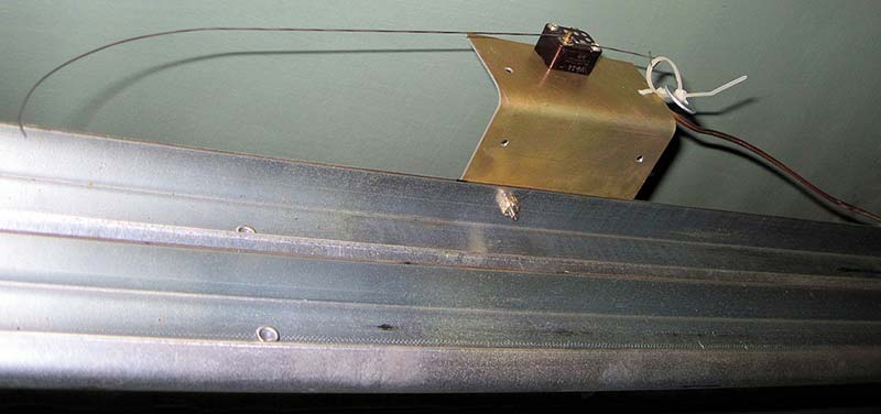
FIGURE 3. Door open sensor switch with music-wire feeler mounted on the garage door track.
I am using a normally-open rotary switch connected to a piece of music wire. When the garage door is closed, SW2 is open and the reset pin of the 4060 is pulled high by R1. When the garage door reaches the top of its travel, it pushes against the left end of the music wire which rotates the shaft of SW2 by 90 degrees, causing it to close. When SW2 closes, it grounds the reset pin of the 4060 allowing the count to start from zero.
I built the closer circuit on a small perf board (RadioShack 276-148) shown in Figure 4.
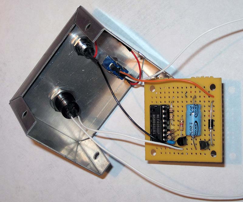
FIGURE 4. Garage door closer circuit mounted inside a project box.
The perf board and the manual controls were installed in a small (2.5 x 2 x 1.5 inch) aluminum project box that I mounted on my garage wall (Figure 5). This was a fun project to build. It’s actually useful and it doesn’t even use a microcontroller!
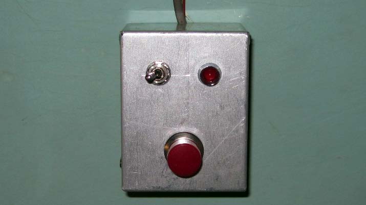
FIGURE 5. Completed project mounted on garage wall.
Building Your Own
If you are thinking of building your own garage door closer circuit, here are some things you should consider:
- Check the voltage and current available at your automatic garage door operator’s local pushbutton. Depending on the voltage available, you may want to use a 78L12 or 78L05 instead of the 78L15.
- Determine the voltage and duration of the pulse needed to trigger your automatic garage door operator; mine was 0.3V or less for 100 milliseconds.
- Note that a CMOS 4060 can operate from three to 15 volts. A 74HC4060, on the other hand, can operate from two to six volts.
- The closing time for my circuit varies from three minutes and 15 seconds in the summer to three minutes and 45 seconds in the winter. I did not use temperature stable components. If you want a more consistent closing time, use temperature stable precision components for Ct and Rt.
- Shorter closing delays can be achieved by using one of the 4060’s less significant outputs — like Q12 or Q10 — or by increasing the frequency of the oscillator.
- Longer closing delays can be obtained by connecting the Q14 output of the 4060 to the clock input of another counter — like a 4040, 12-stage binary counter. If you do this, be sure to connect the reset pin of the 4040 to the reset pin of the 4060 so both chips start counting from zero.
- I used a rotary microswitch to detect the garage door was open because I happened to have it available. A magnetic switch — like those used as door and window sensors in alarm systems — would probably be more reliable in the long run.
Hope you find this circuit as handy as I do. NV
Parts LIST
| QTY |
PART |
REFERENCE |
| 1 |
100 µF, 35V |
C1 |
| 1 |
0.1 µF, 35V |
Ct |
| 2 |
100K, 0.25W, 5% |
R1, Rt |
| 1 |
2.2M, 0.25W, 5% |
R2 |
| 1 |
4.7K, 0.25W, 5% |
R3 |
| 1 |
1K, 0.25W, 5% |
R4 |
| 1 |
1N4001 |
D1 |
| 1 |
LED, red |
D2 |
| 1 |
2N3904 |
Q1 |
| 1 |
78L15 |
U1 |
| 1 |
4060 |
U2 |
| 1 |
DPST toggle |
SW1 |
| 1 |
Door sensor |
SW2 |
| 1 |
Pushbutton |
PB1 |